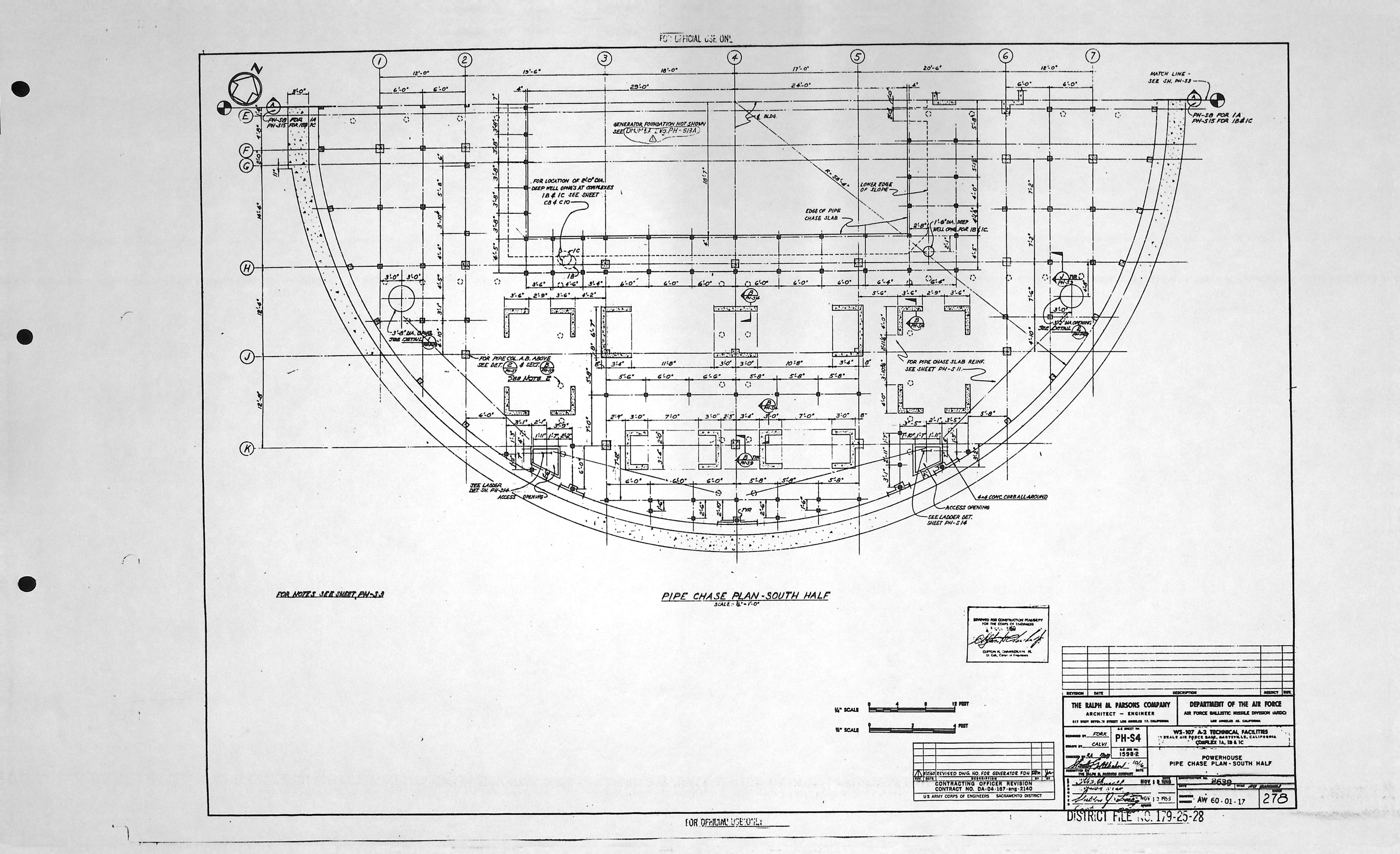
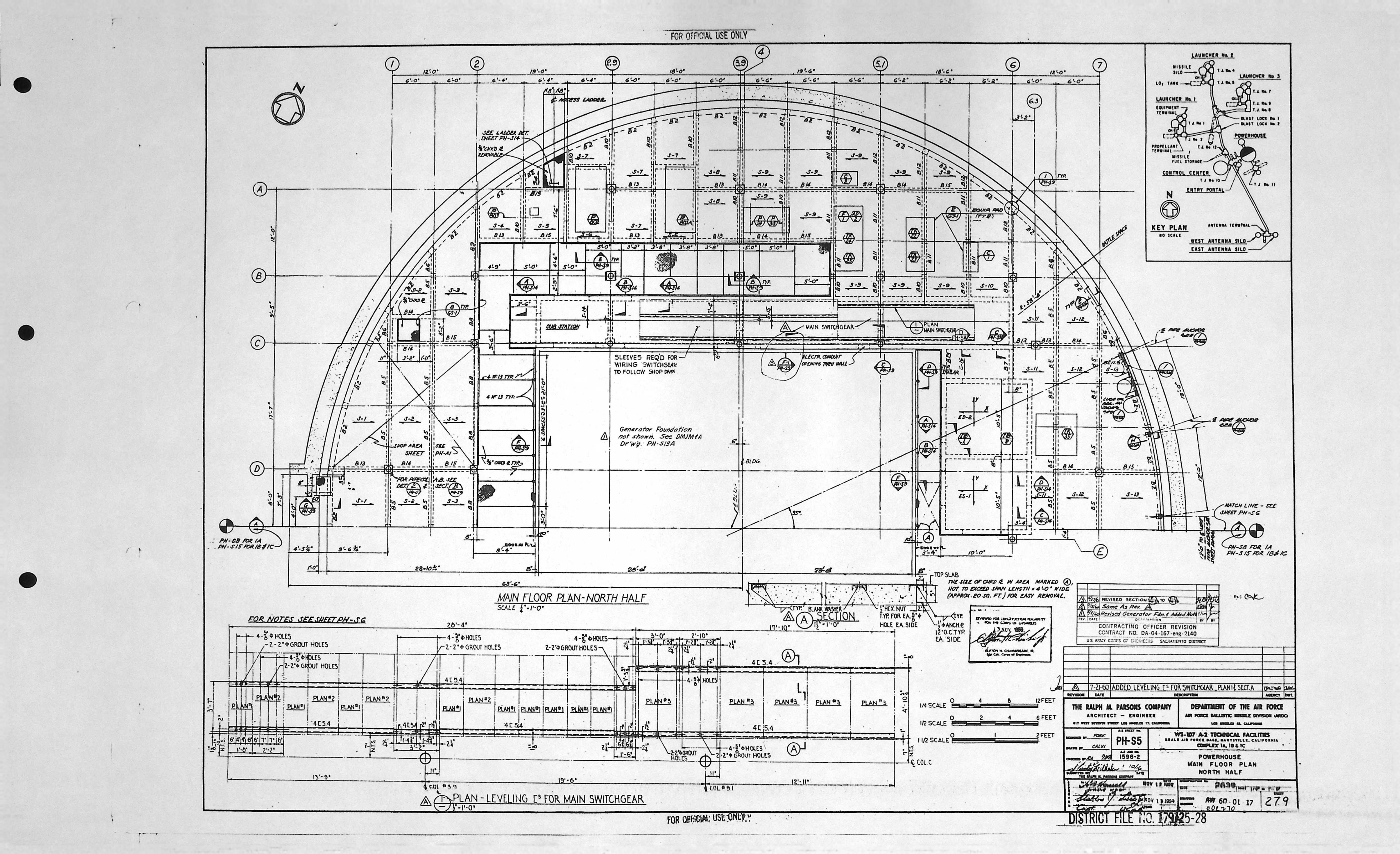
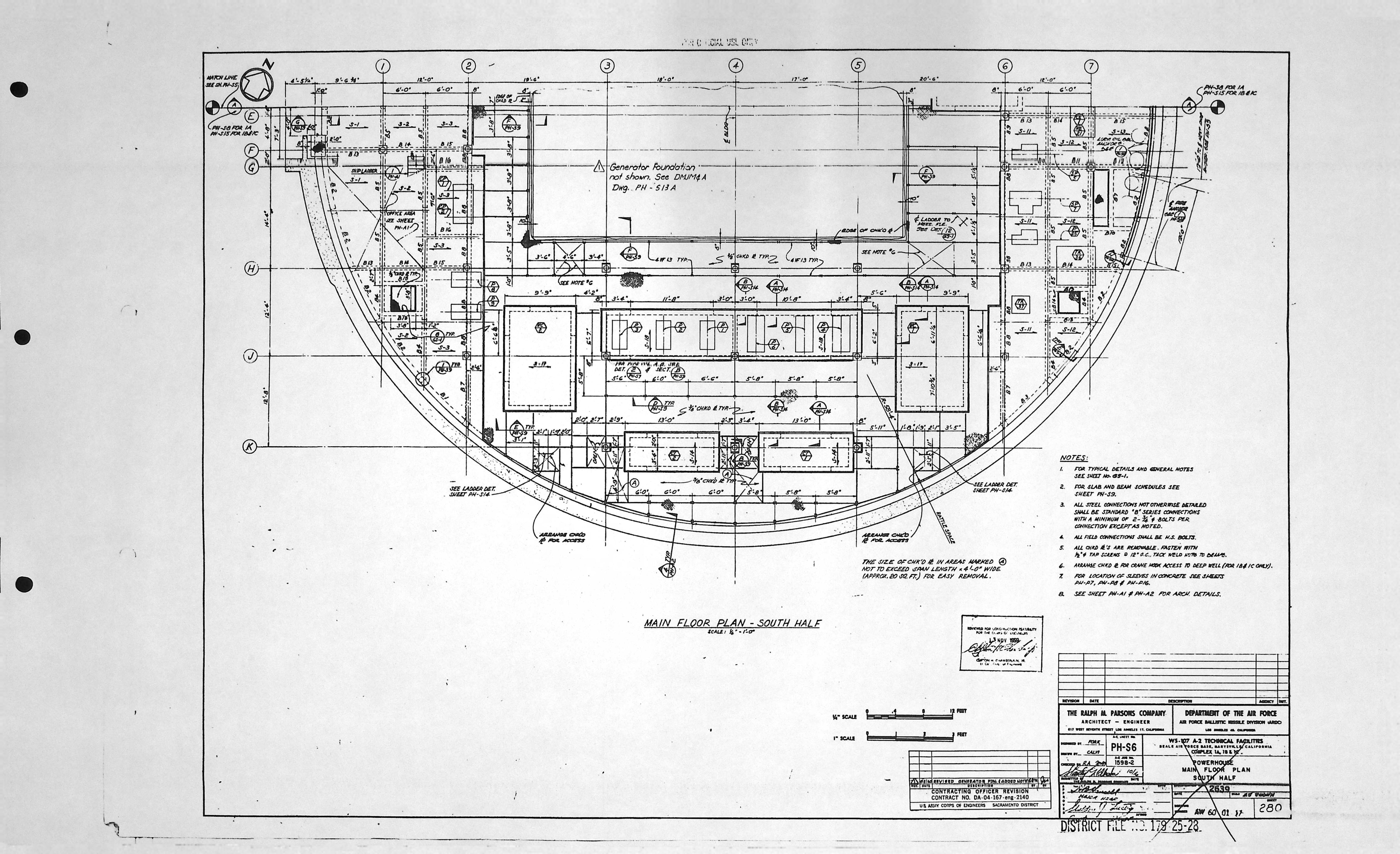
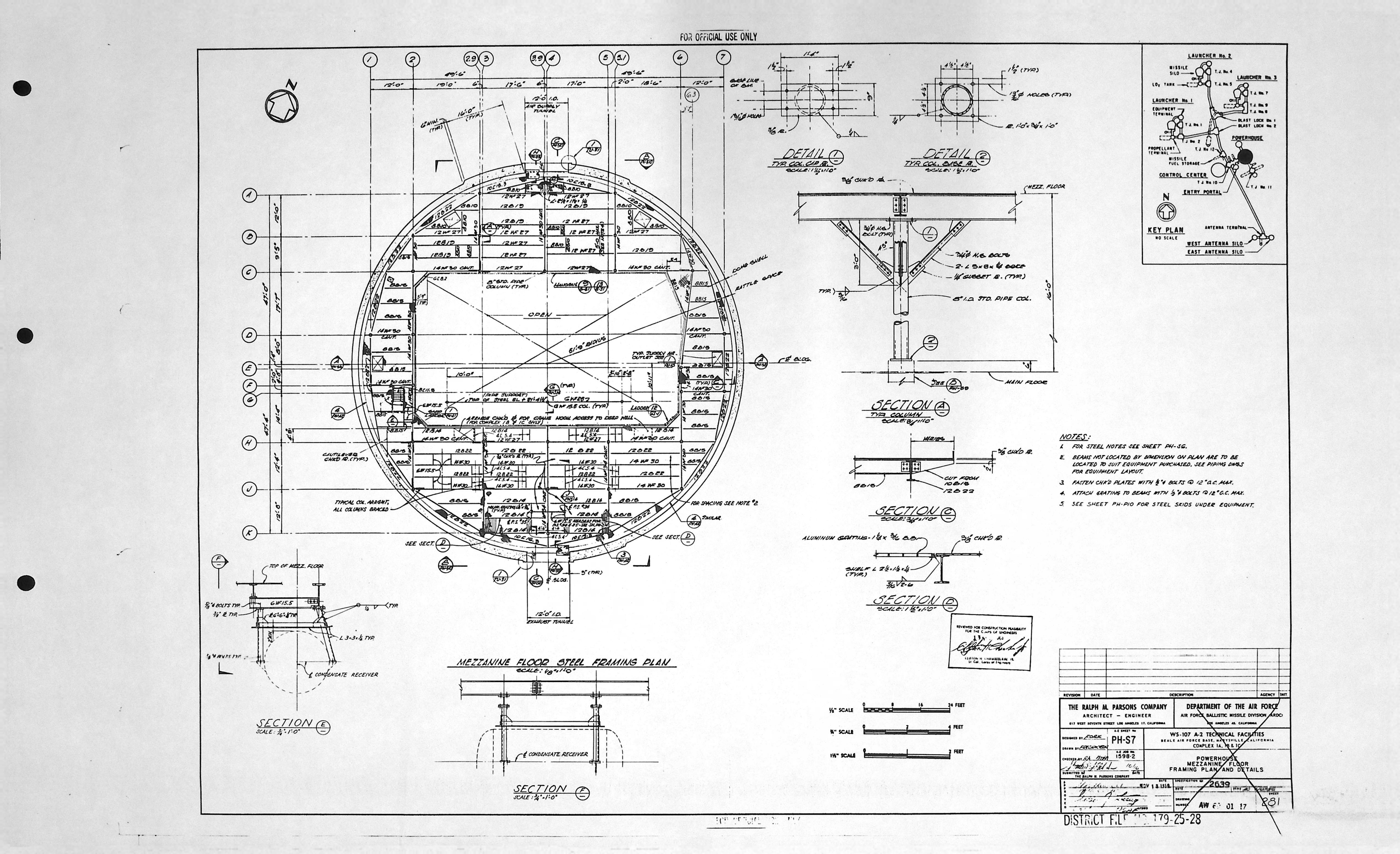
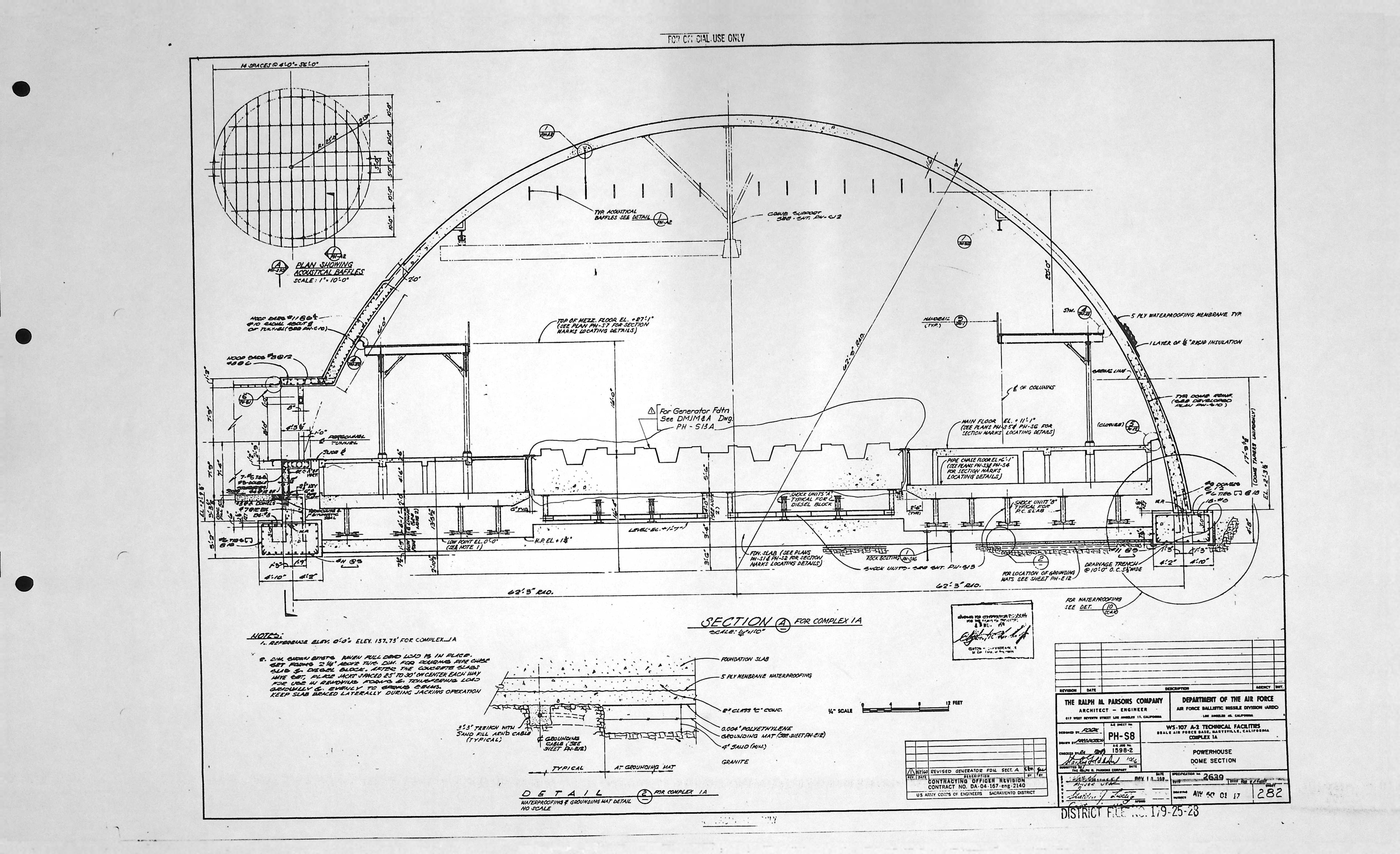
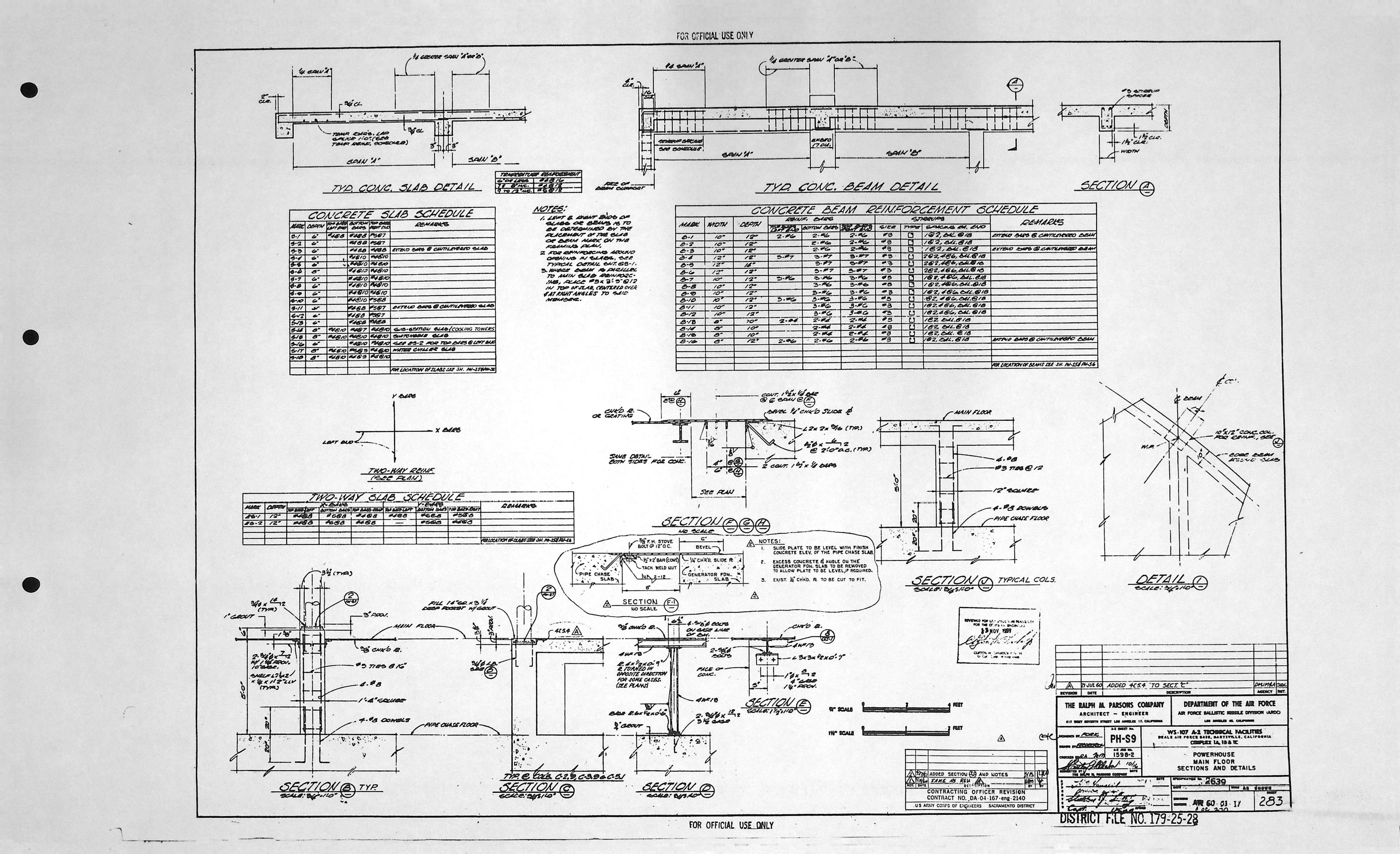
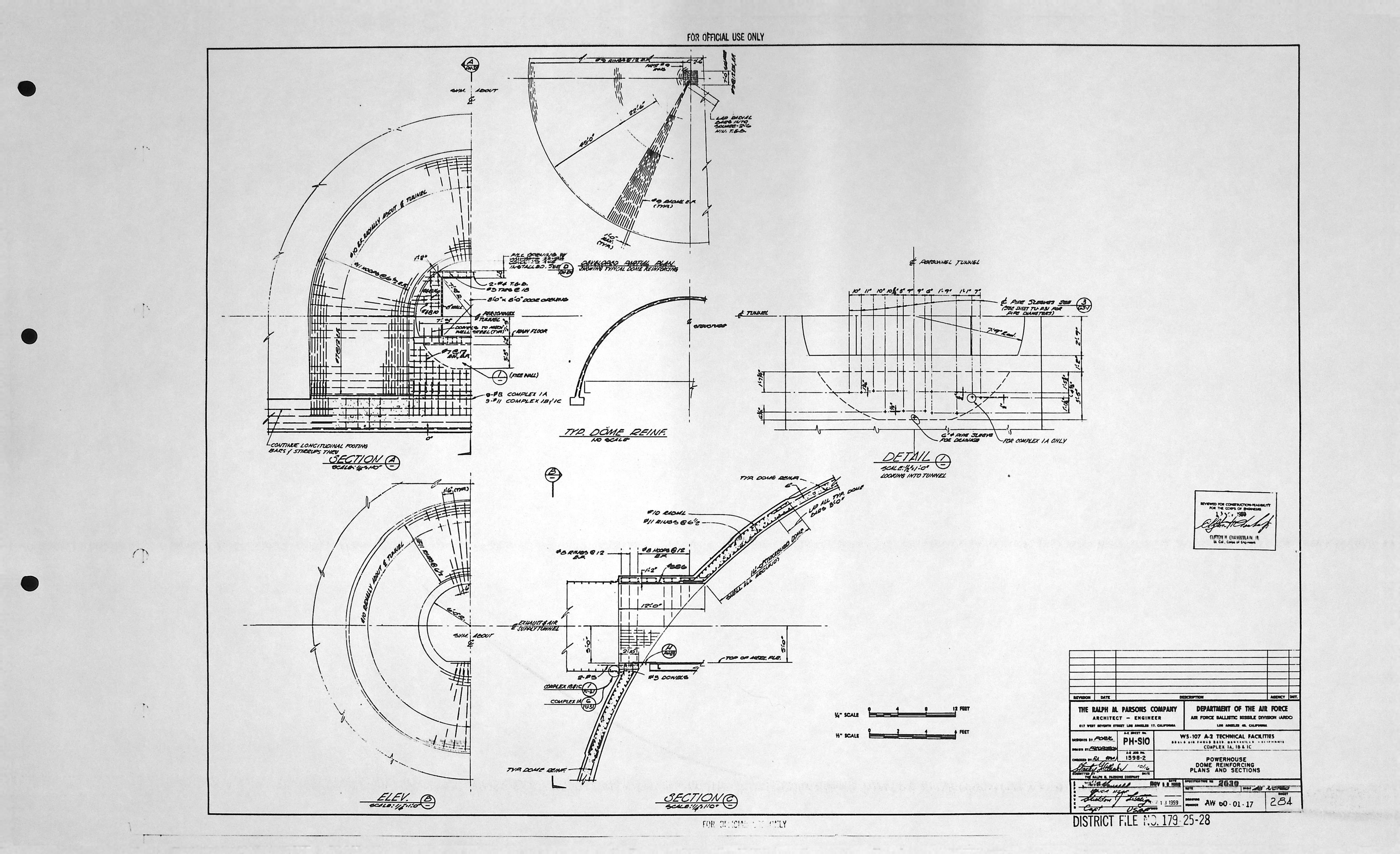
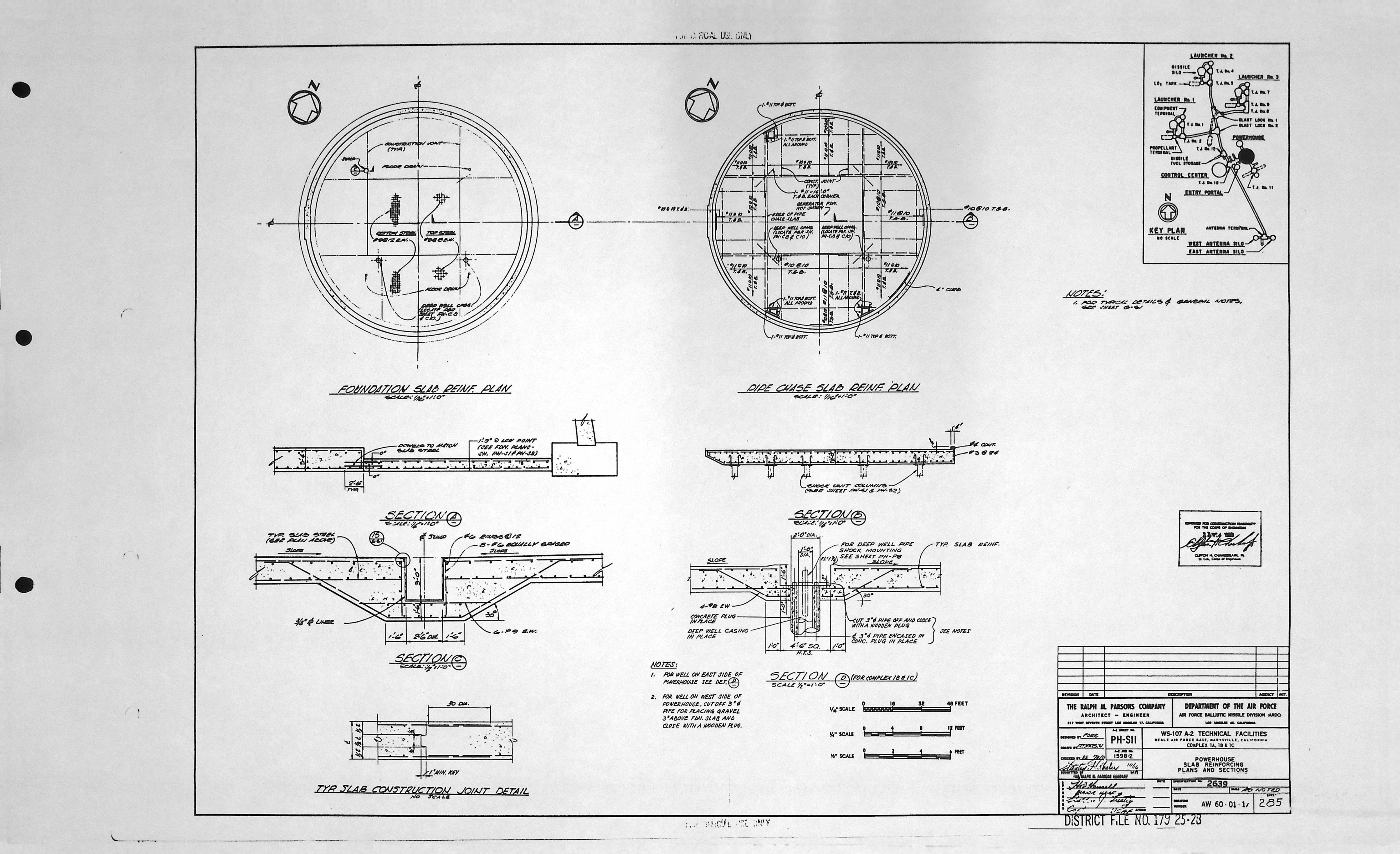
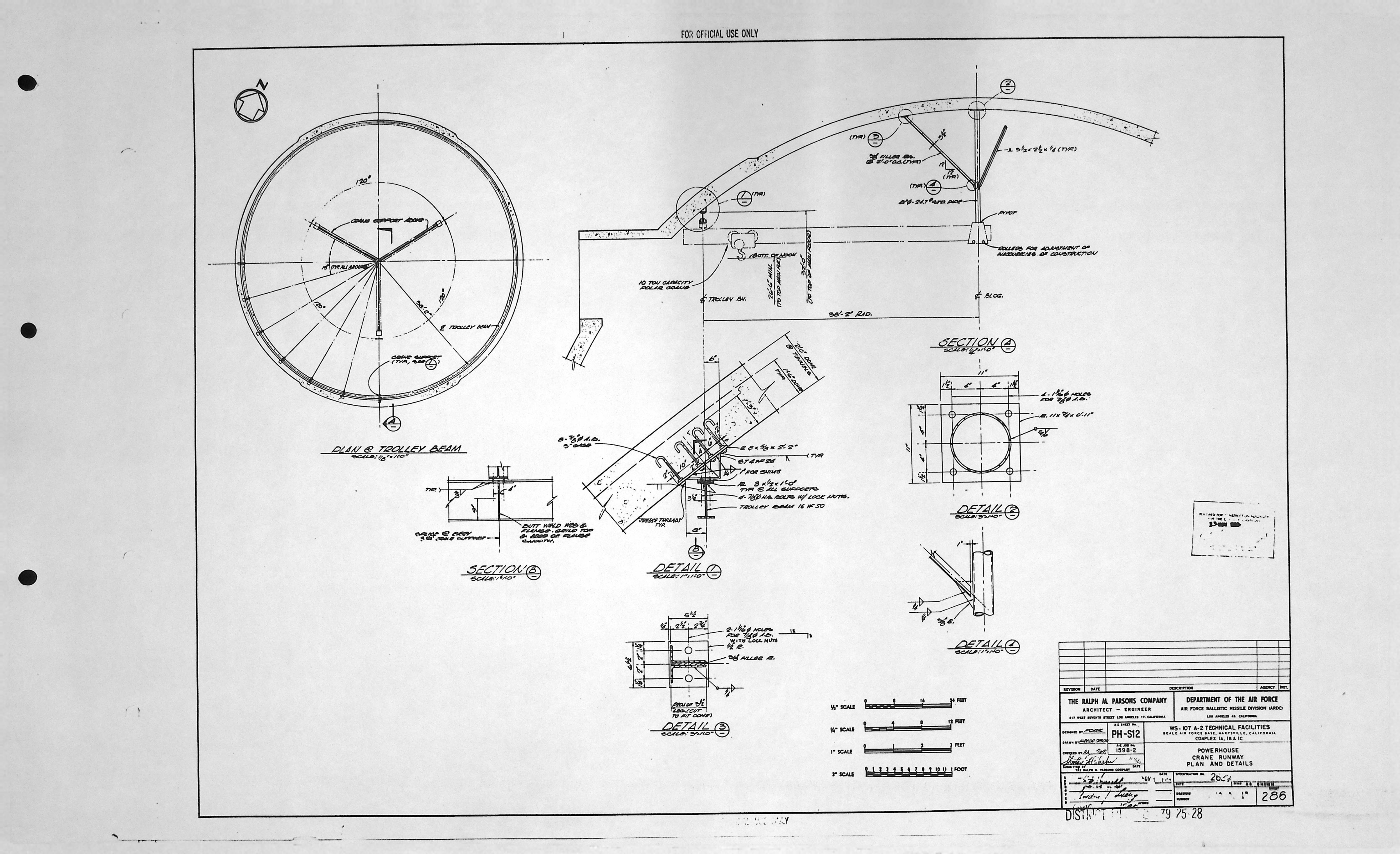
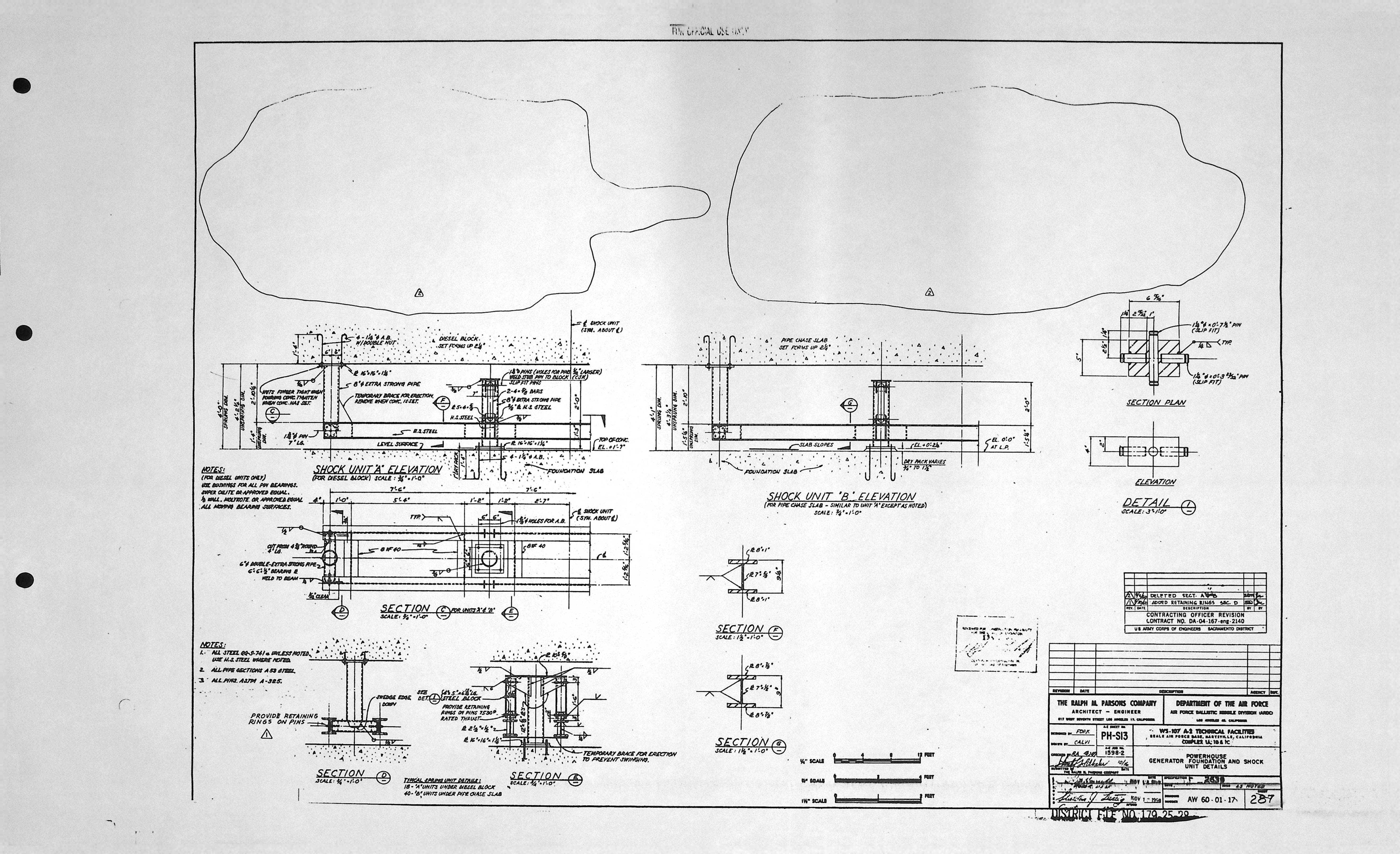
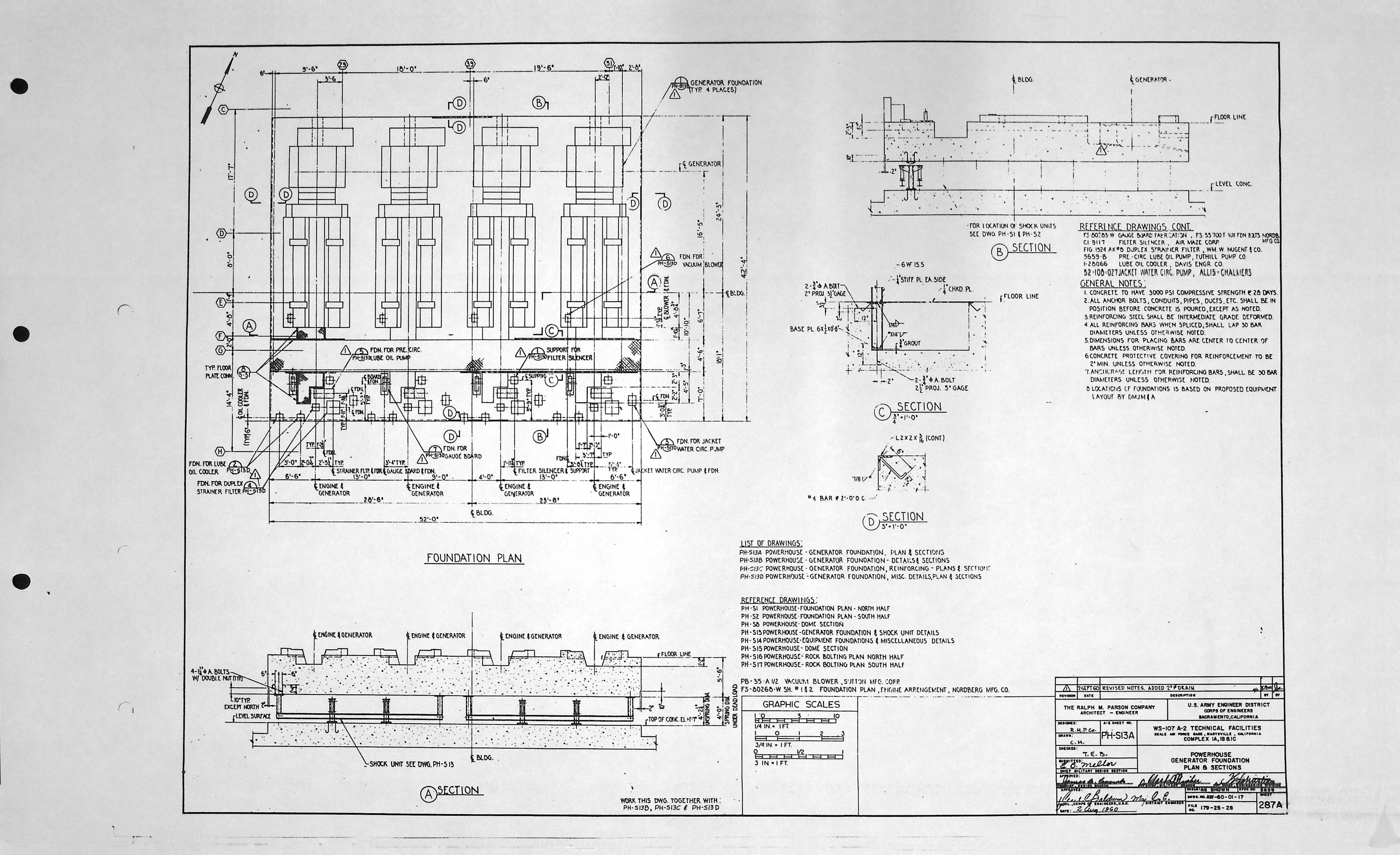
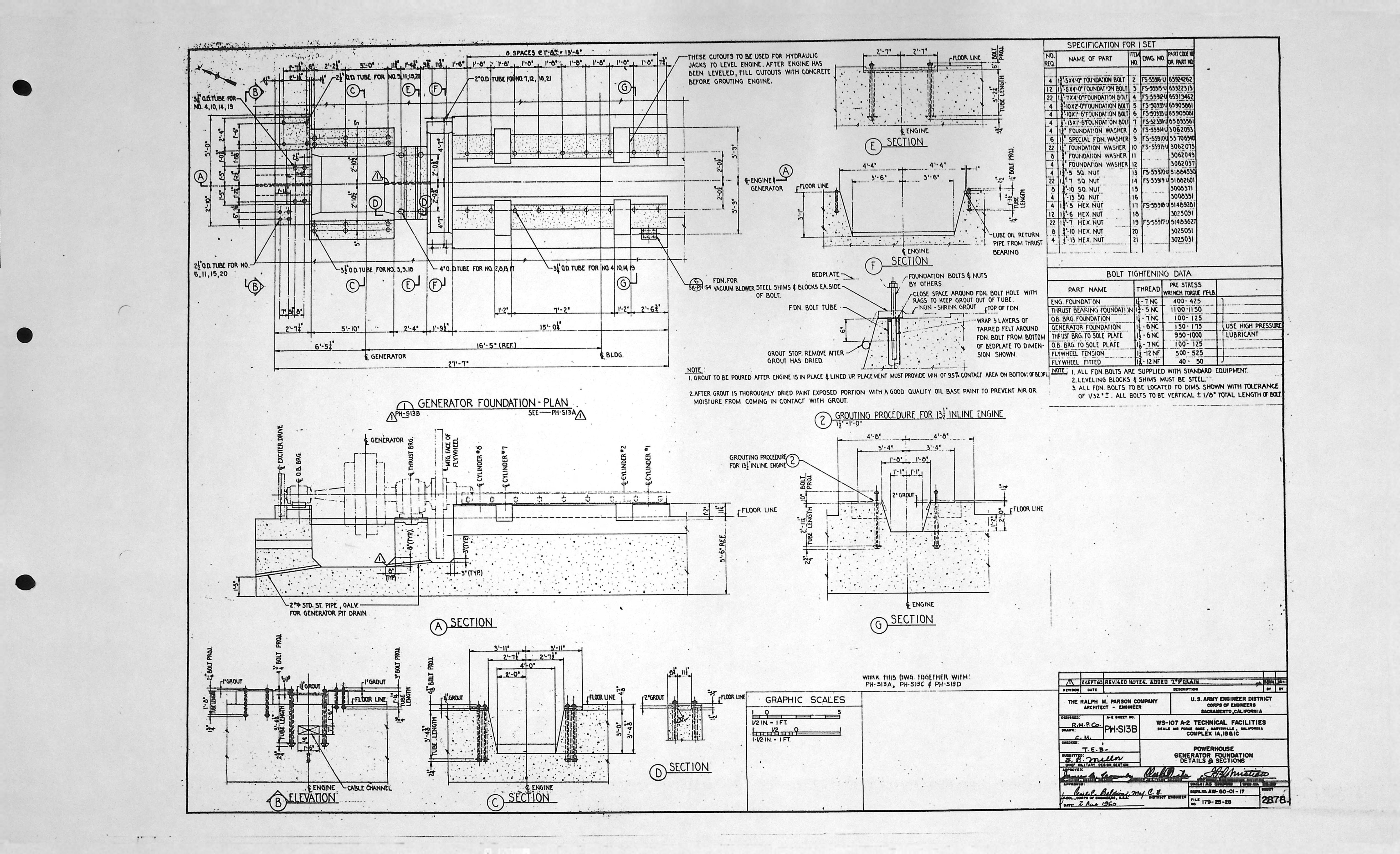
Power House - Architectural drawings (2)
| Drawing Number | Description |
|---|---|
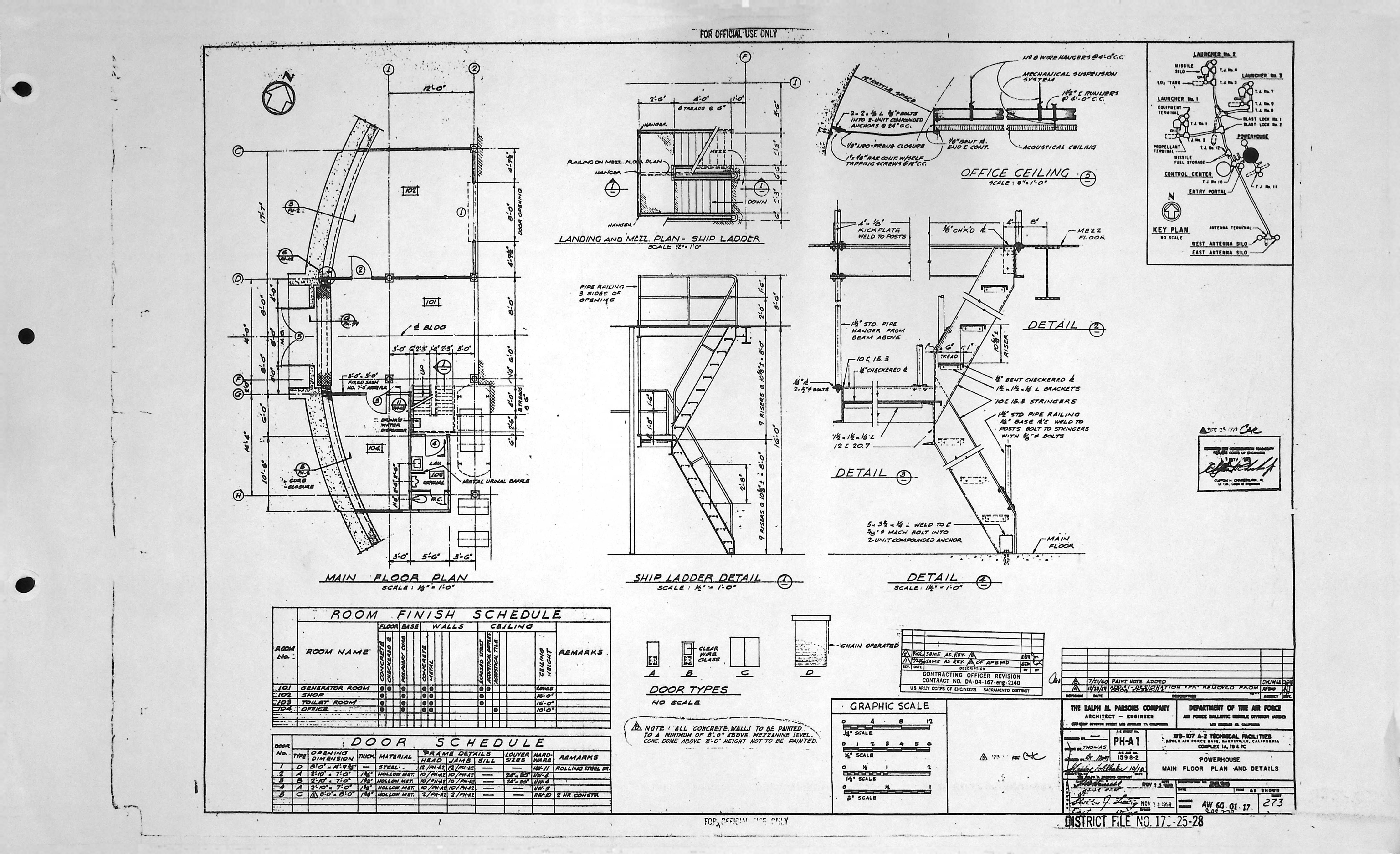
| PH-A1 | MAIN FLOOR PLAN AND DETAILS |
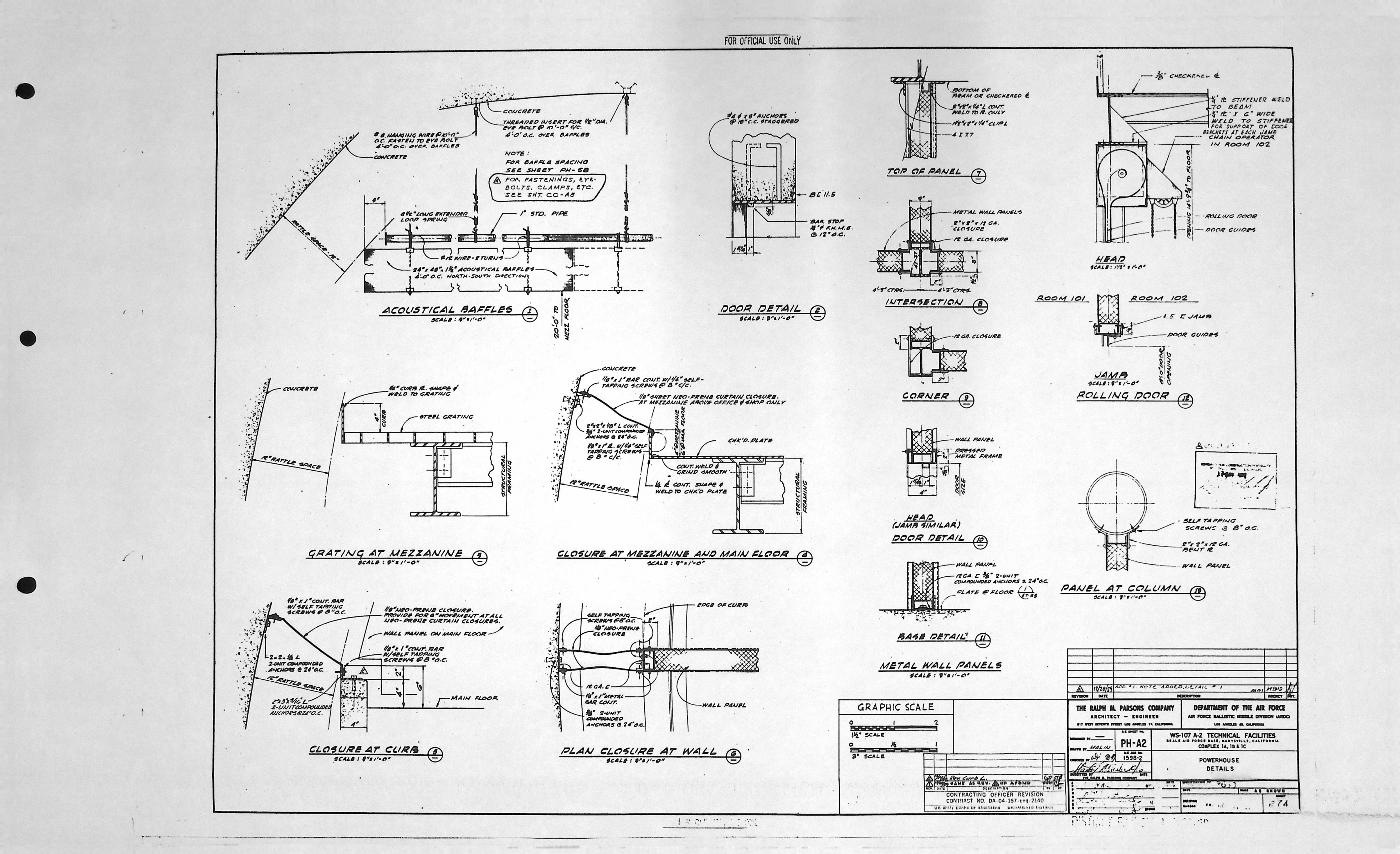
| PH-A2 | POWERHOUSE DETAILS |
Power House - Composite drawings (0)
| Drawing Number | Description |
|---|---|
| -- | N/A |
Power House - Electrical drawings (23)
| Drawing Number | Description |
|---|---|
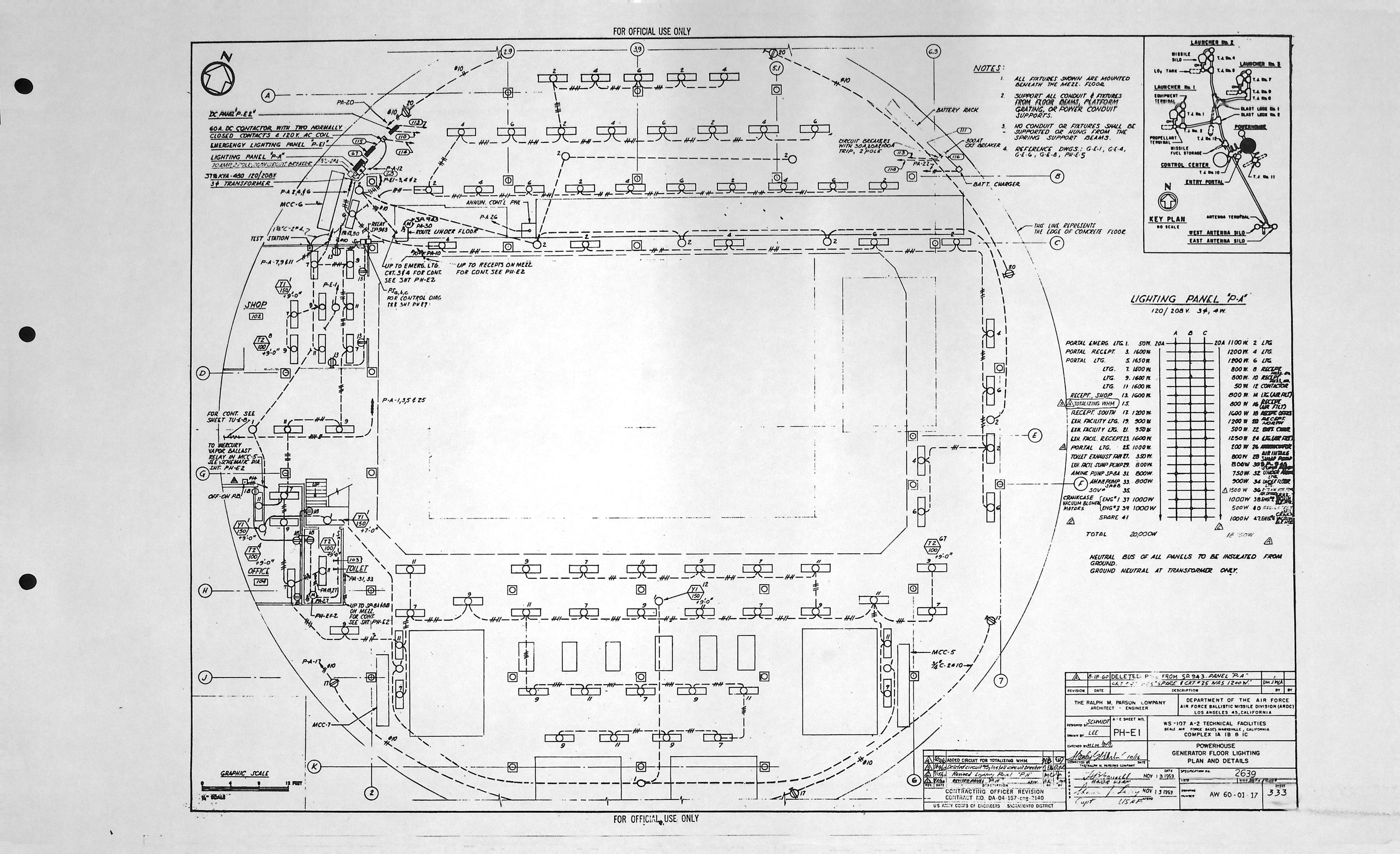
| PH-E1 | GENERATOR FLOOR LIGHTING PLAN & DETAILS |
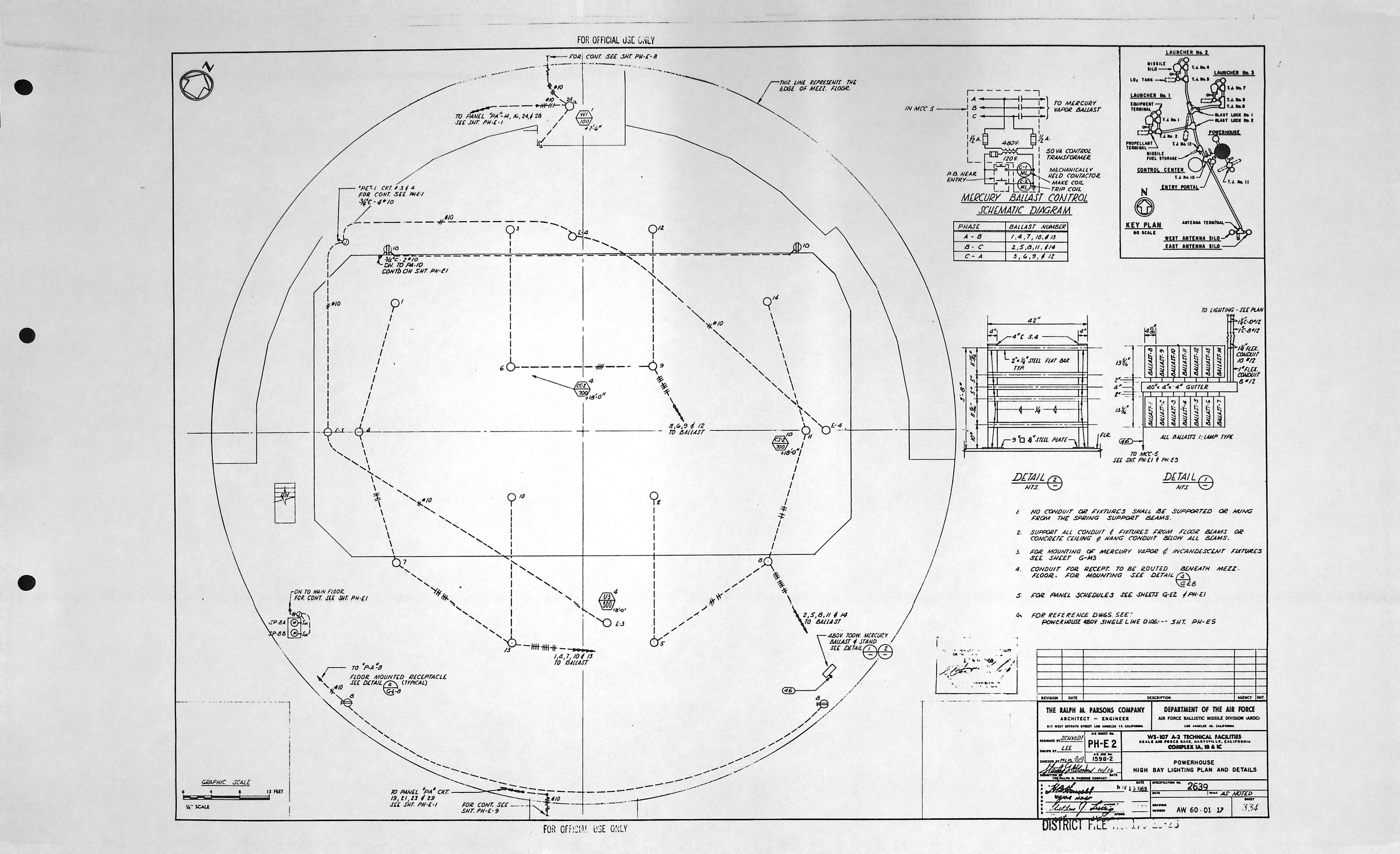
| PH-E2 | HIGH BAY LIGHTING PLAN & DETAILS |
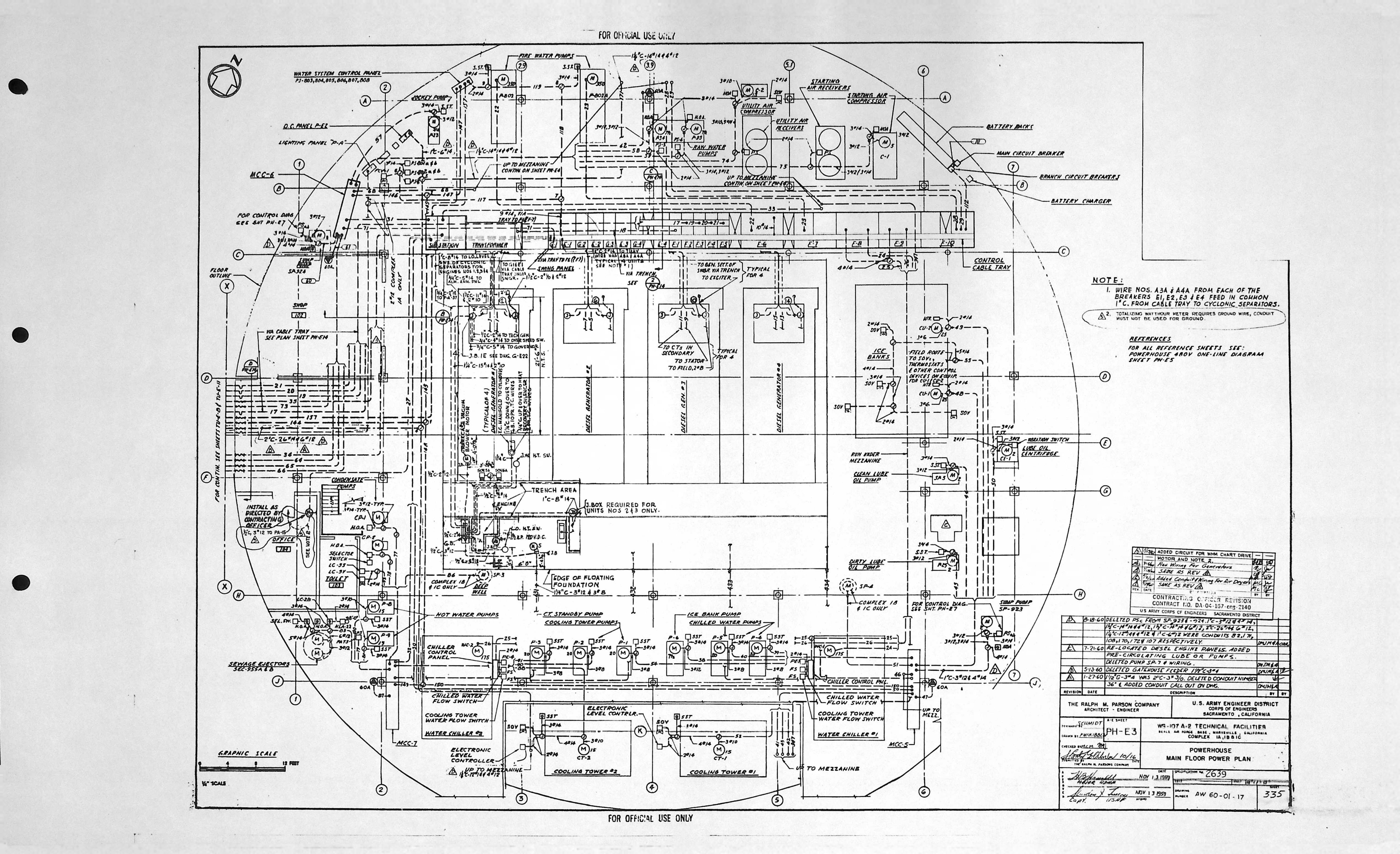
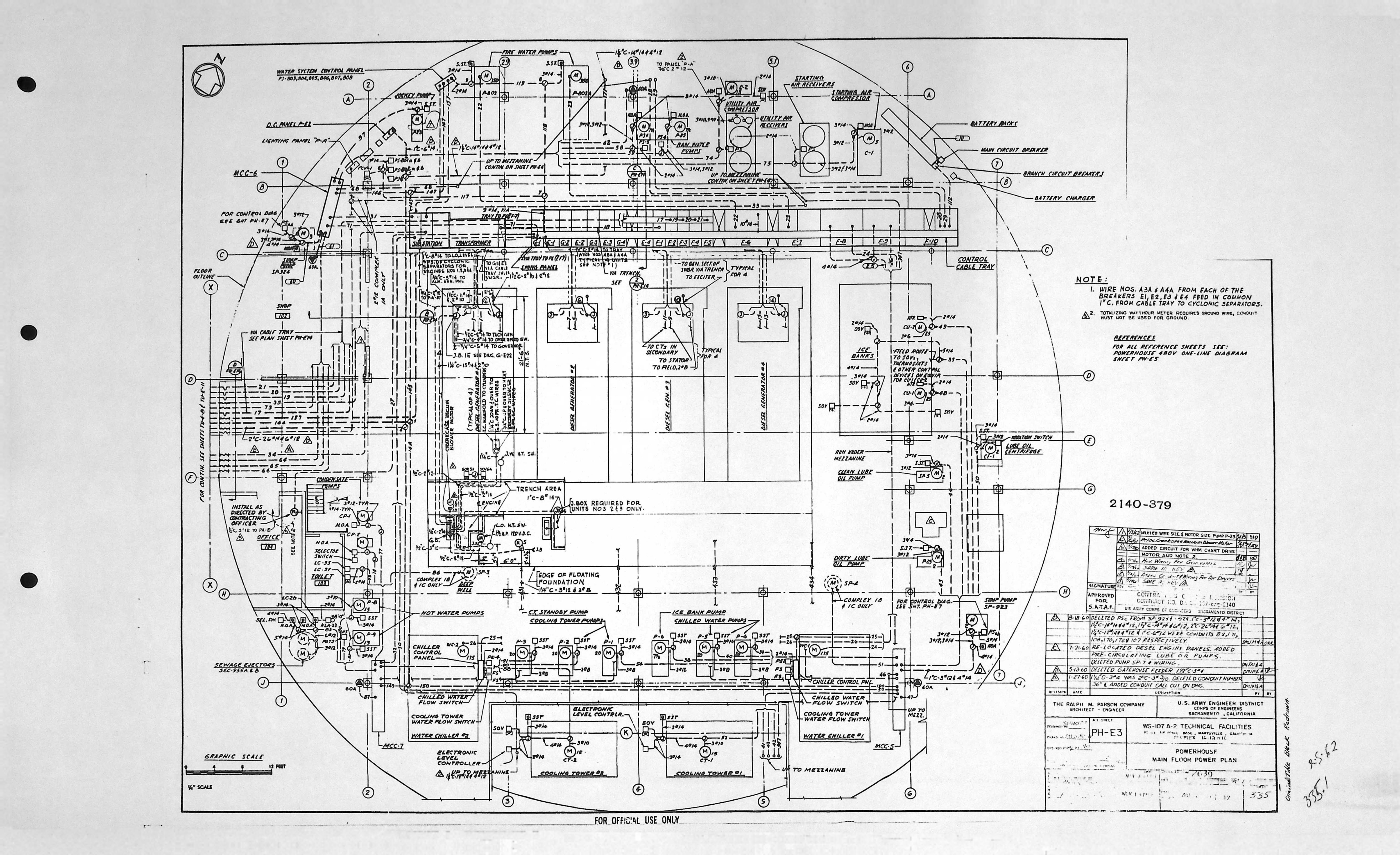
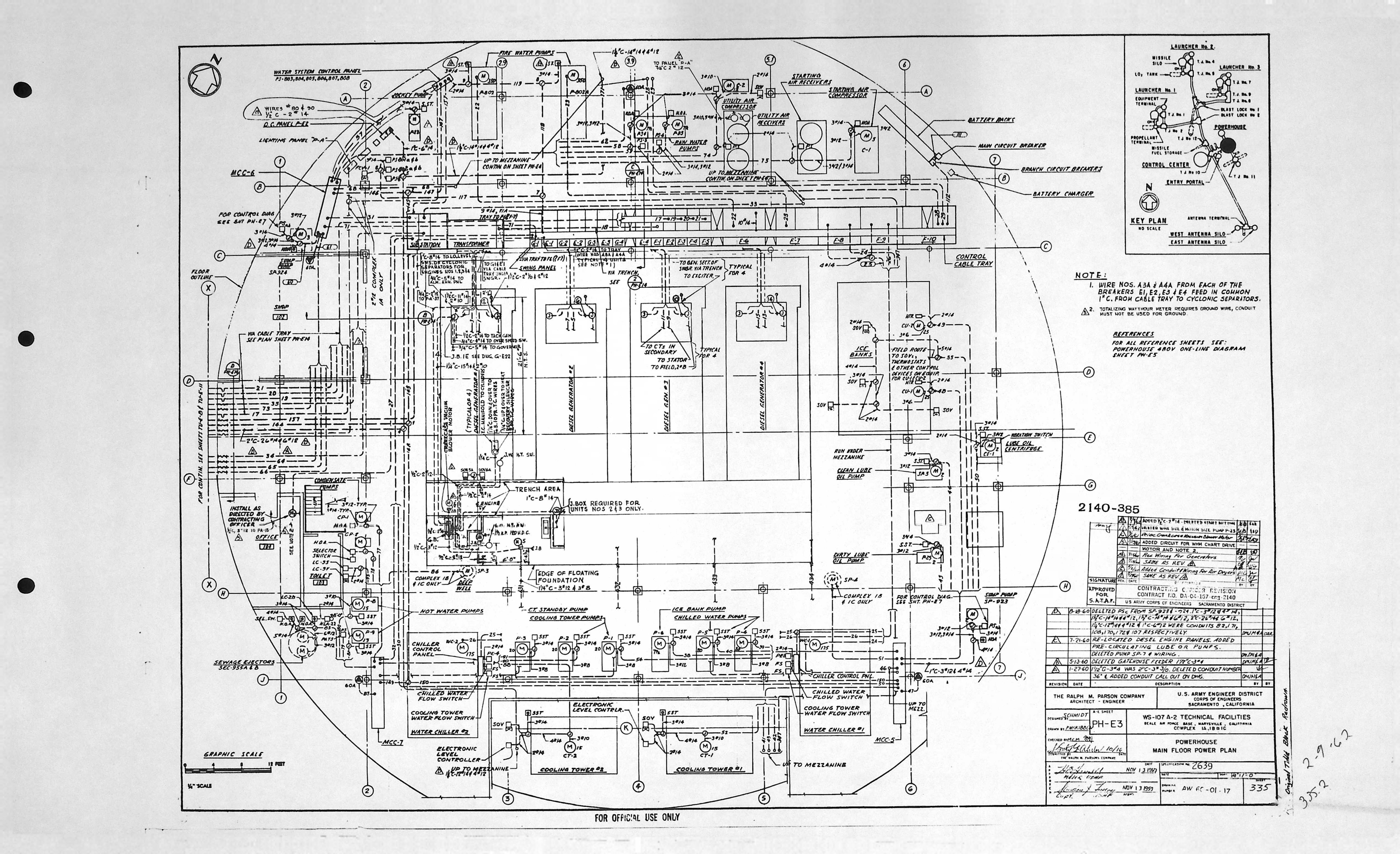
| PH-E3 | MAIN FLOOR POWER PLAN |
| PH-E3 | MAIN FLOOR POWER PLAN * |
| PH-E3 | MAIN FLOOR POWER PLAN * |
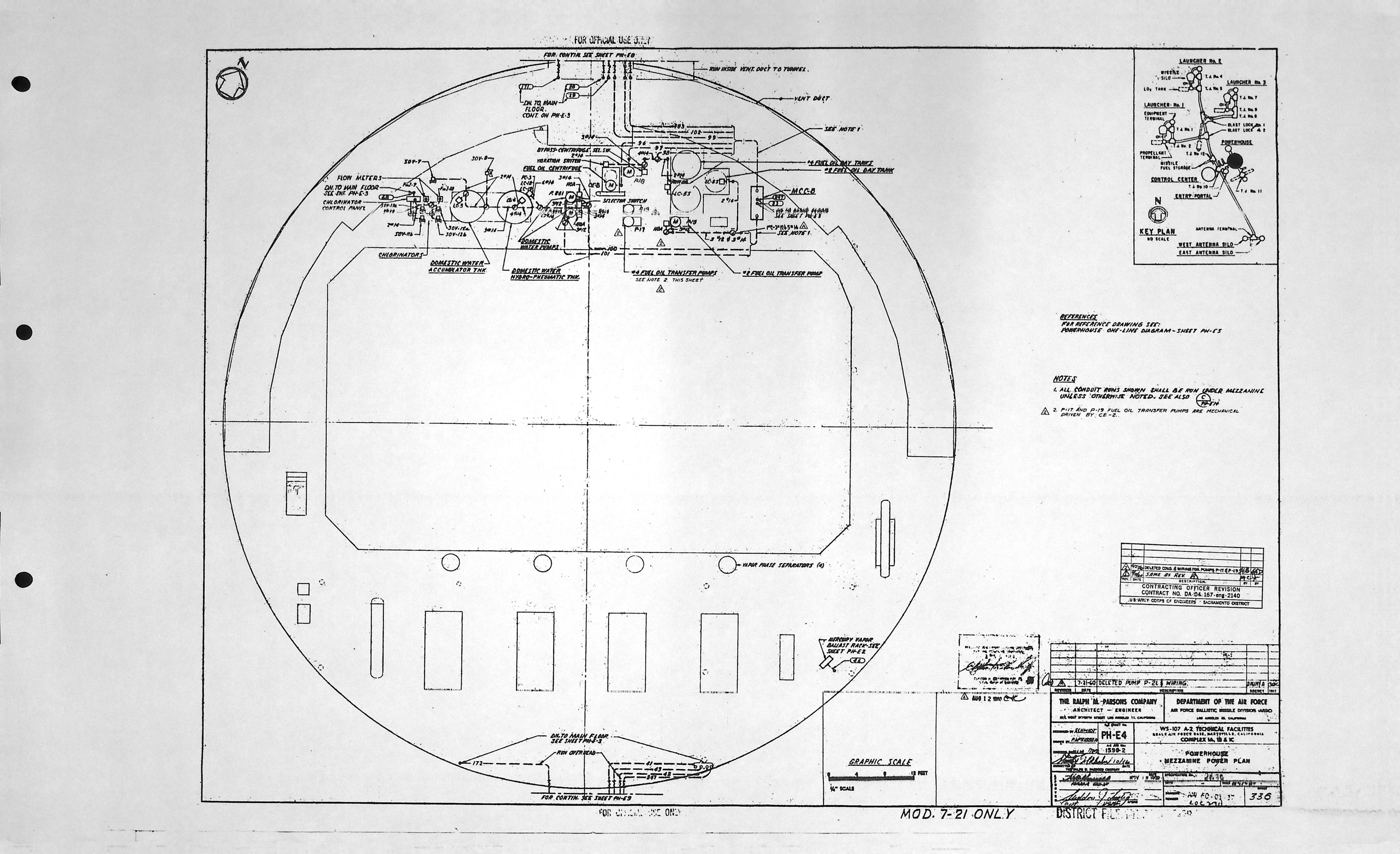
| PH-E4 | MEZZANINE POWER PLAN |
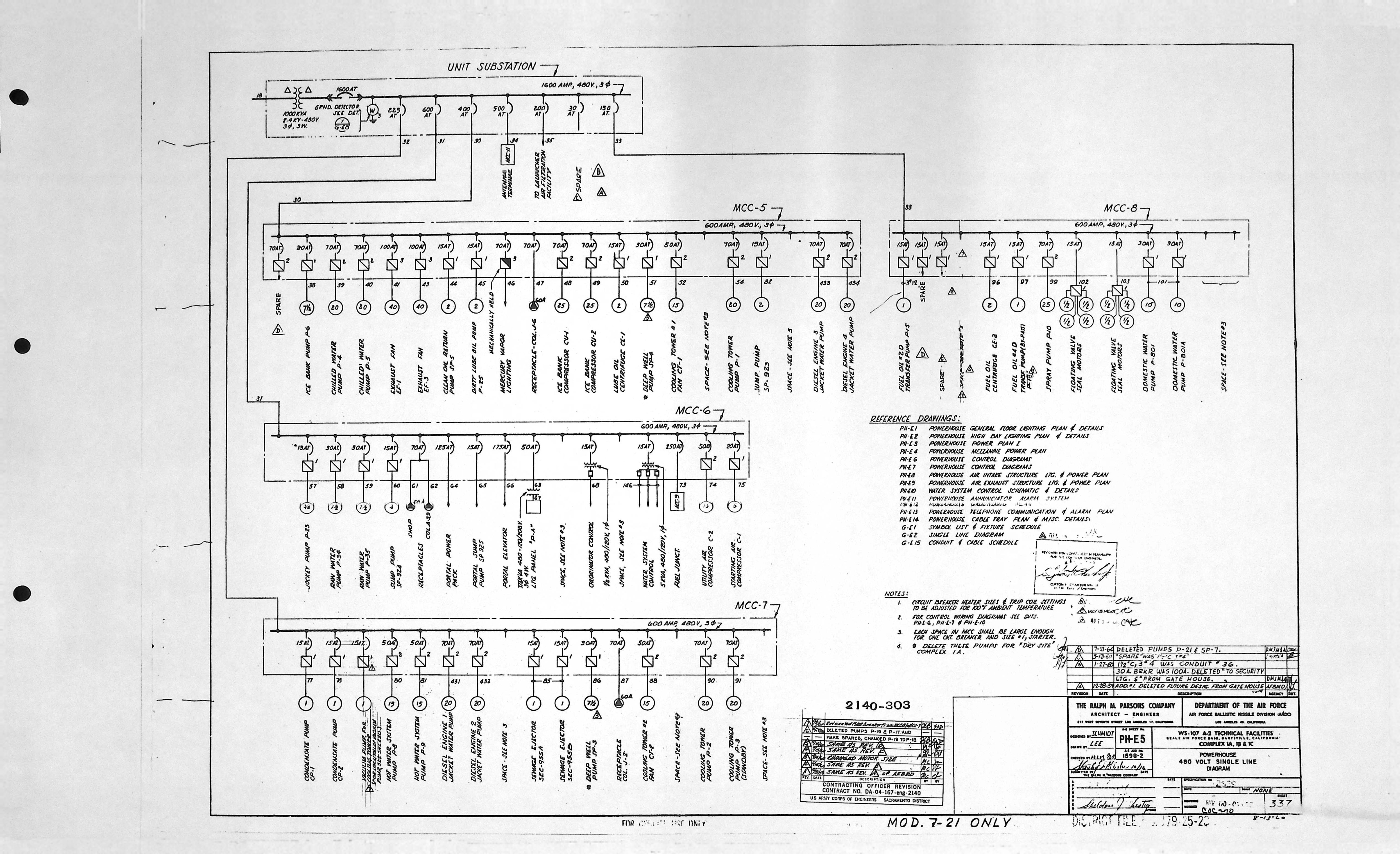
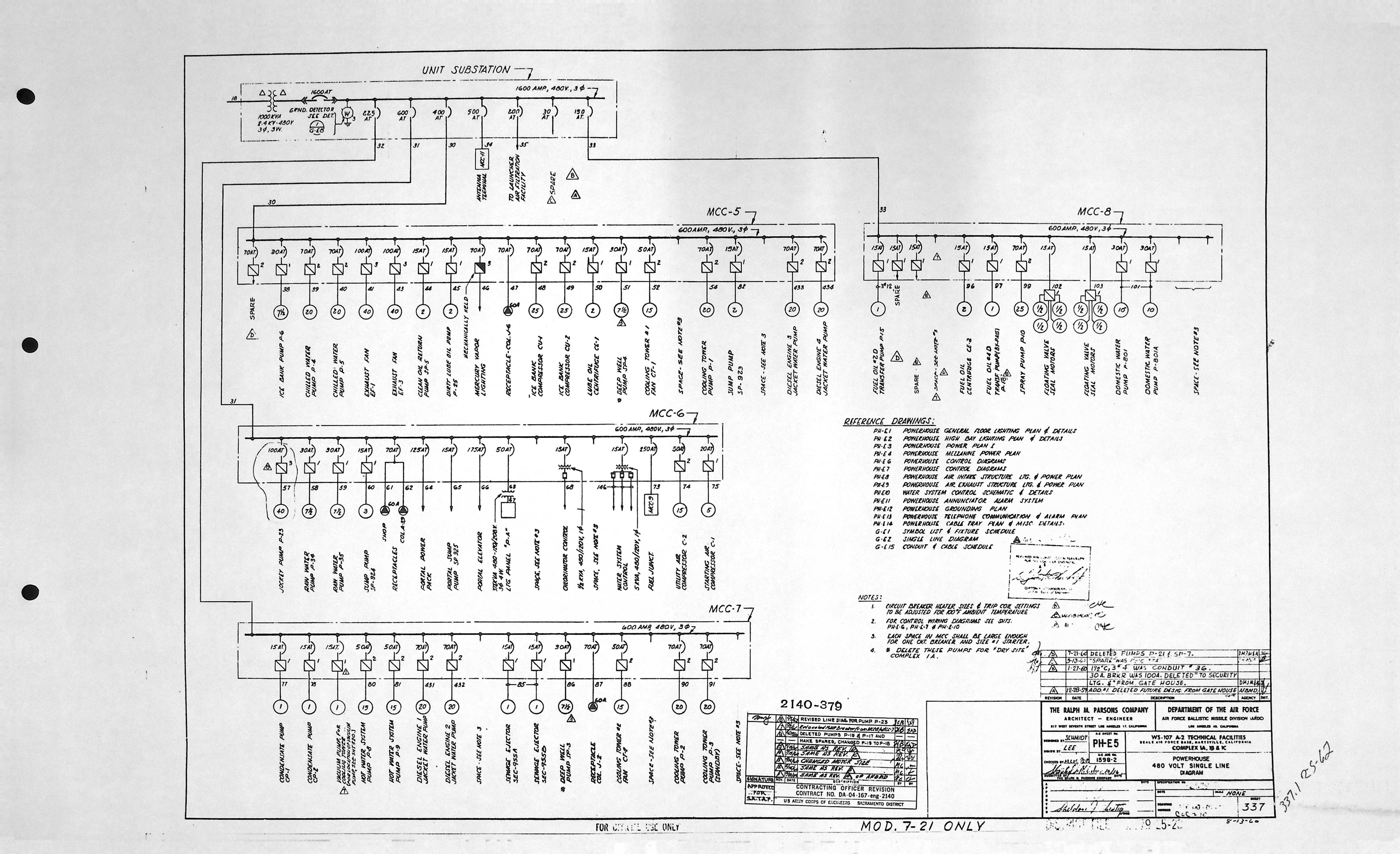
| PH-E5 | 480 VOLT SINGLE LINE DIAGRAM |
| PH-E5 | 480 VOLT SINGLE LINE DIAGRAM * |
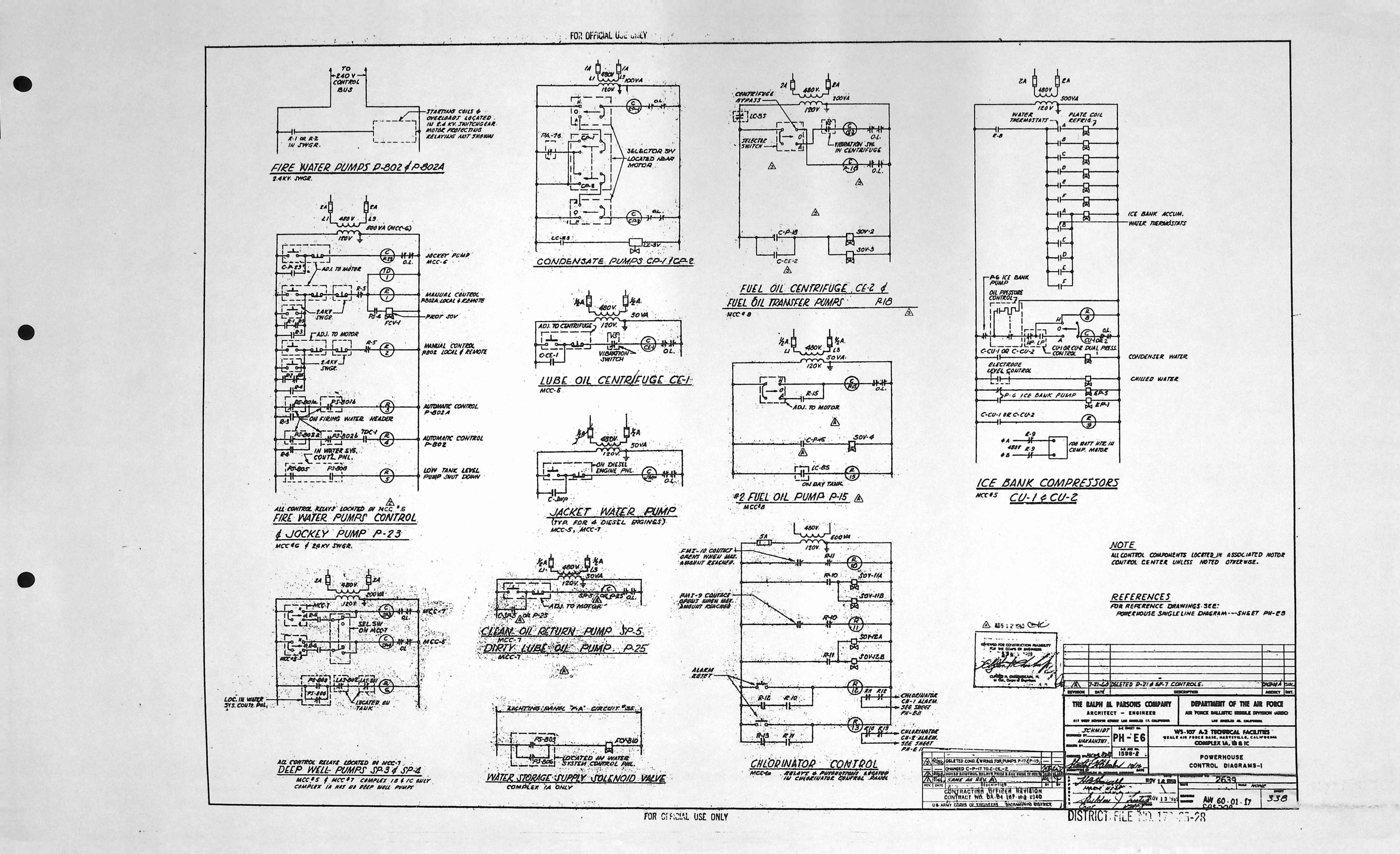
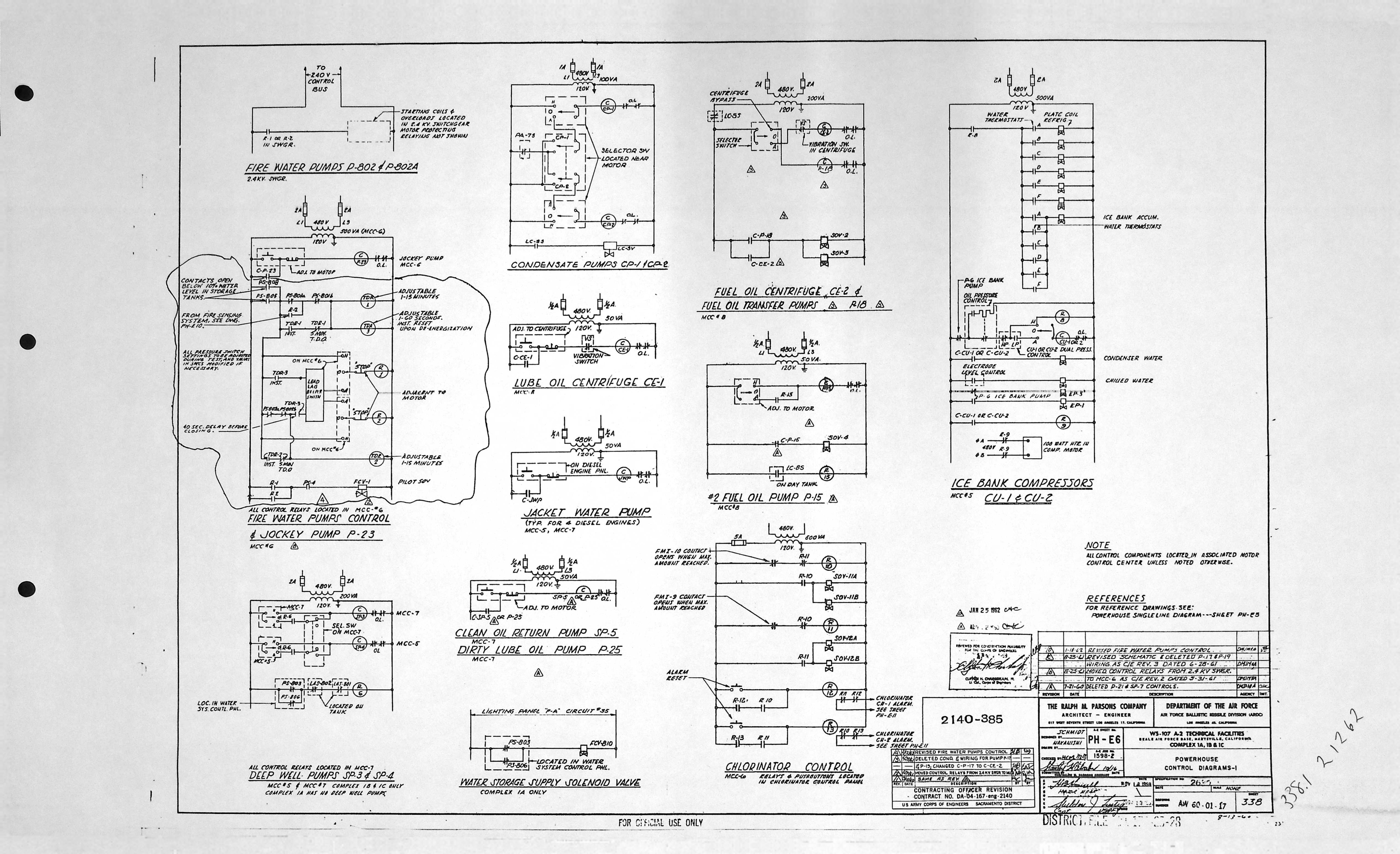
| PH-E6 | CONTROL DIGRAMS - 1 |
| PH-E6 | CONTROL DIGRAMS - 1 * |
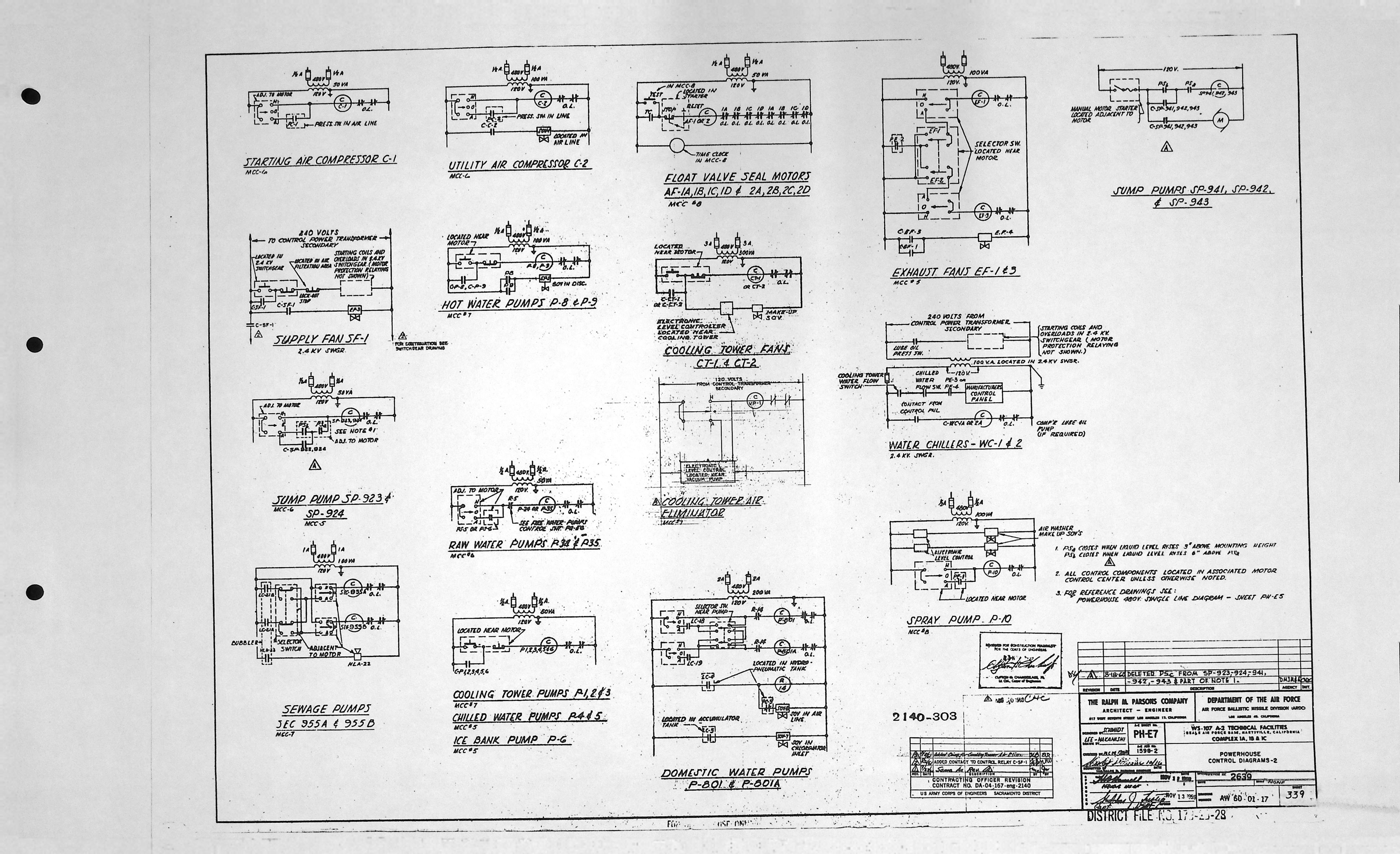
| PH-E7 | CONTROL DIGRAMS - 2 |
| PH-E8 | DELETED OR MISSING † |
| PH-E9 | DELETED OR MISSING † |
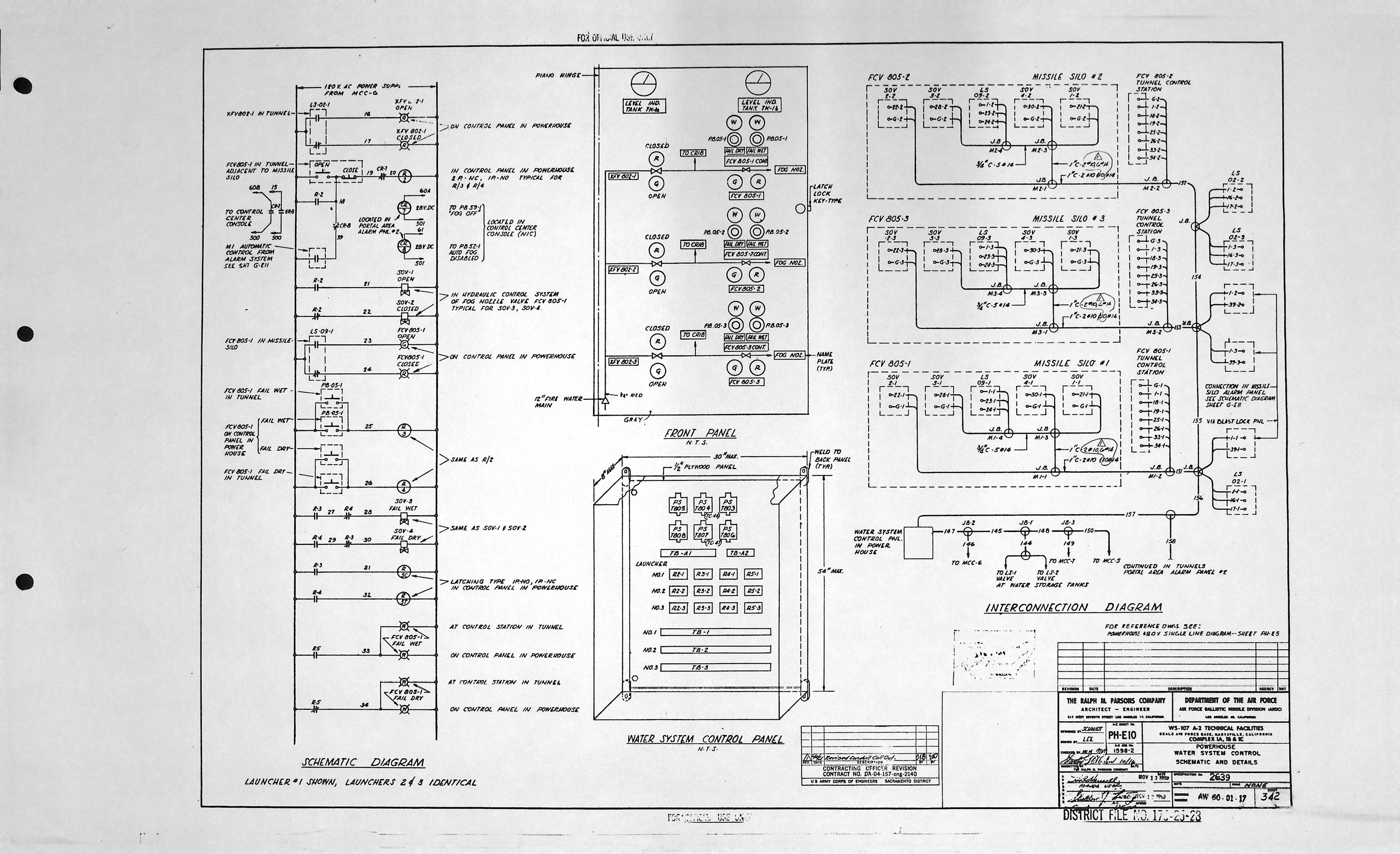
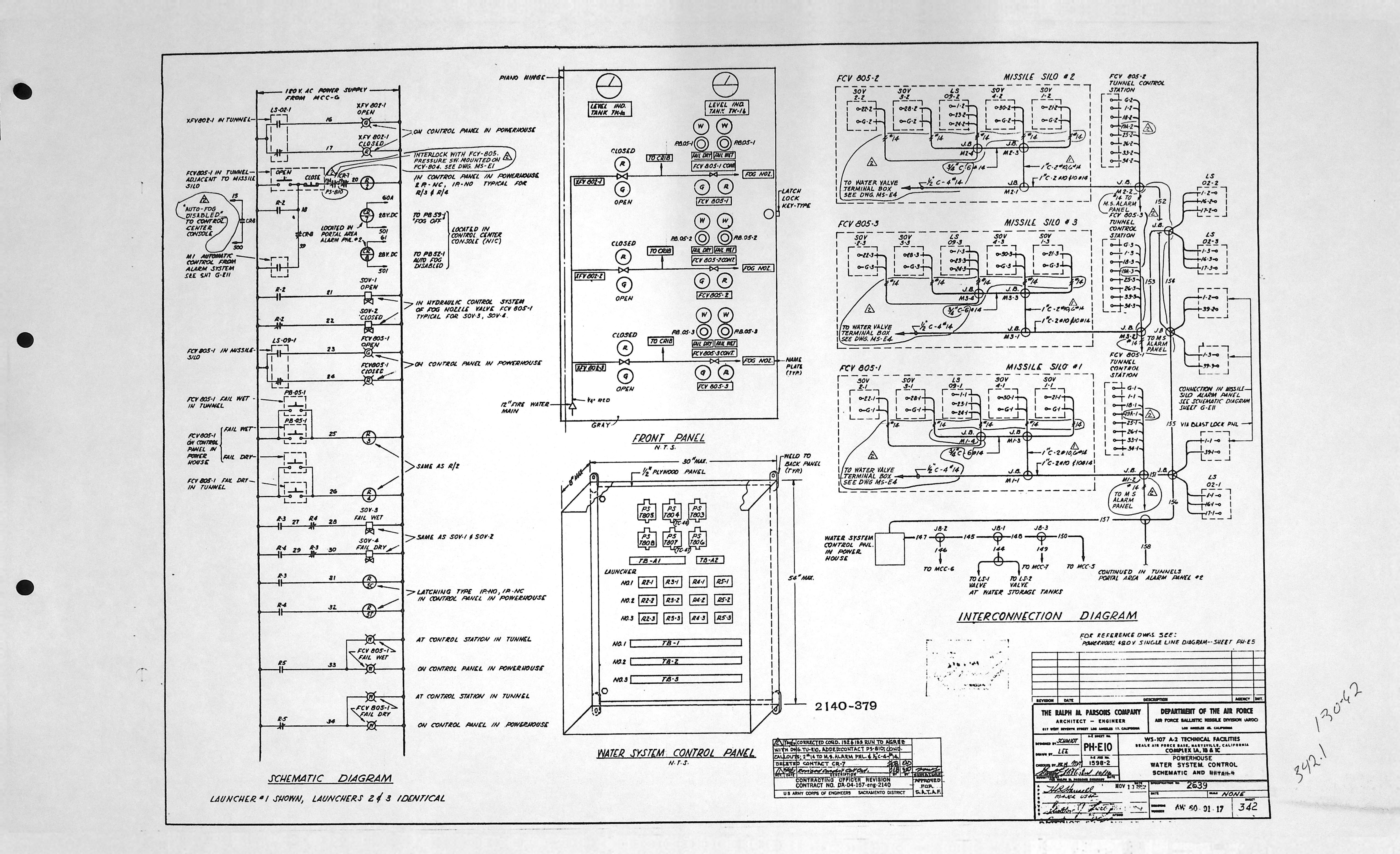
| PH-E10 | WATER SYSTEM CONTROL SCHEMATIC & DETAILS |
| PH-E10 | WATER SYSTEM CONTROL SCHEMATIC & DETAILS * |
| PH-E10 | WATER SYSTEM CONTROL SCHEMATIC & DETAILS * |
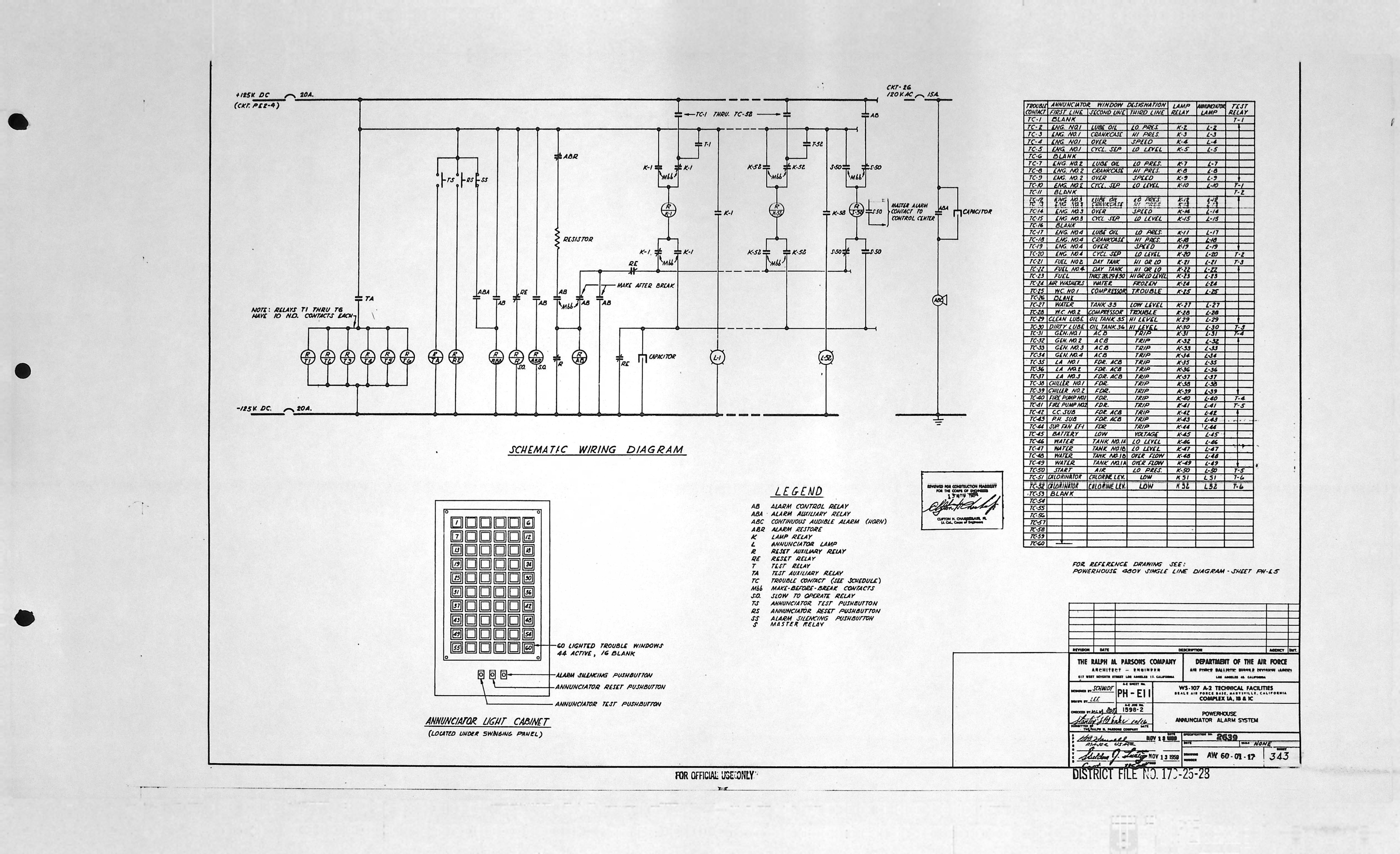
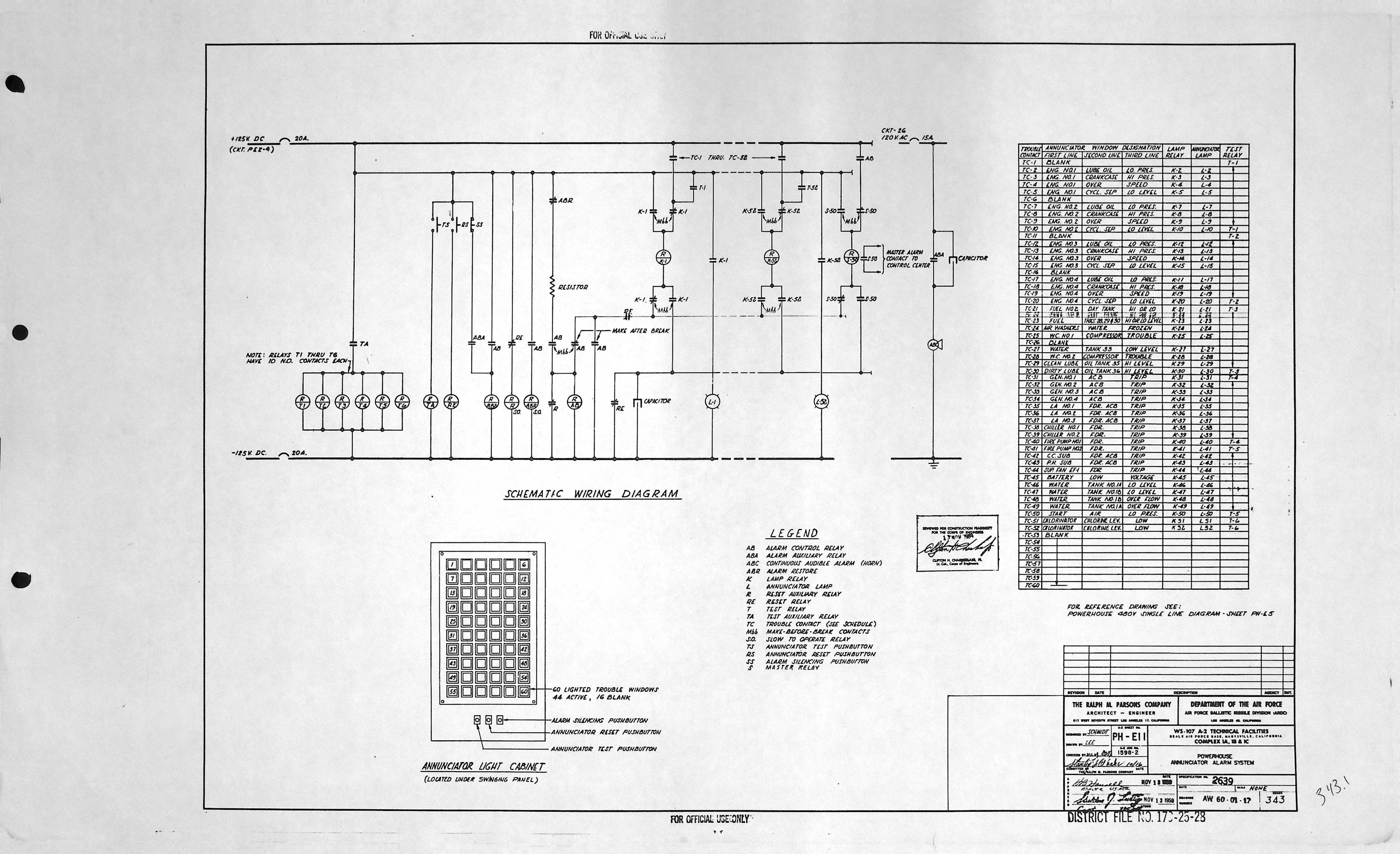
| PH-E11 | ANNUNCIATOR ALARM SYSTEM |
| PH-E11 | ANNUNCIATOR ALARM SYSTEM * |
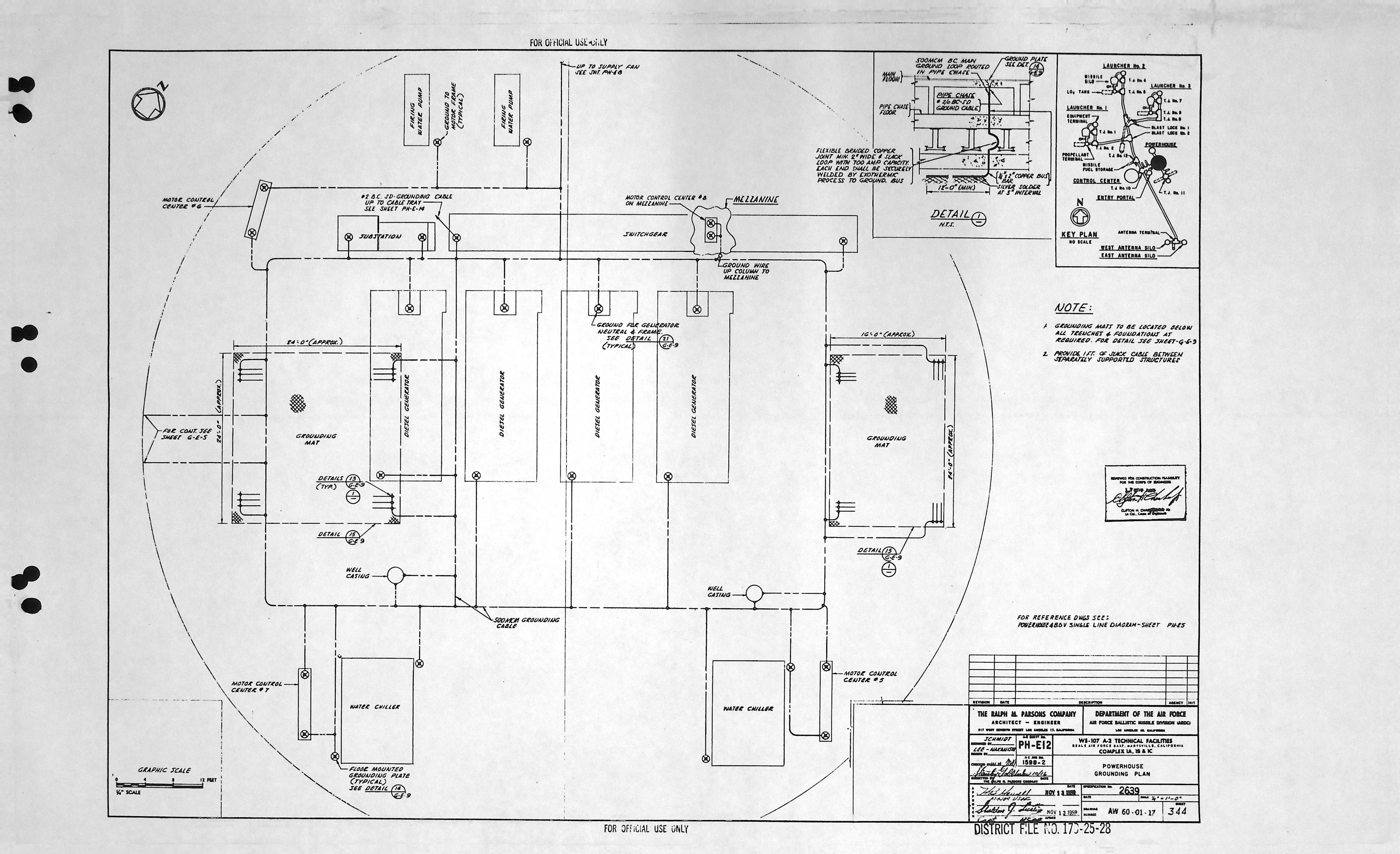
| PH-E12 | GROUNDING PLAN |
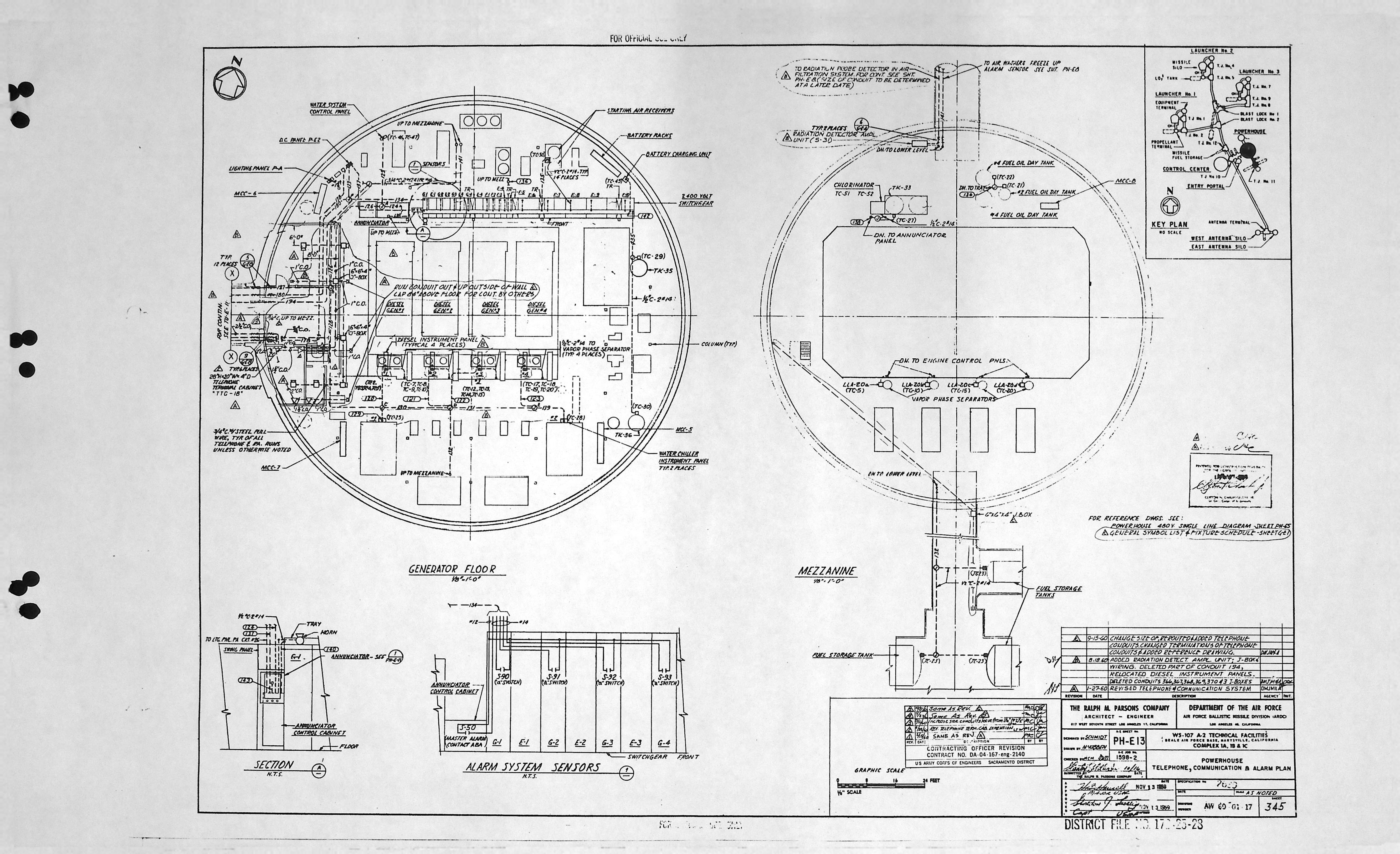
| PH-E13 | GROUNDING |
| PH-E14 | TELEPHONE, COMMUNICATION & ALARM PLAN |
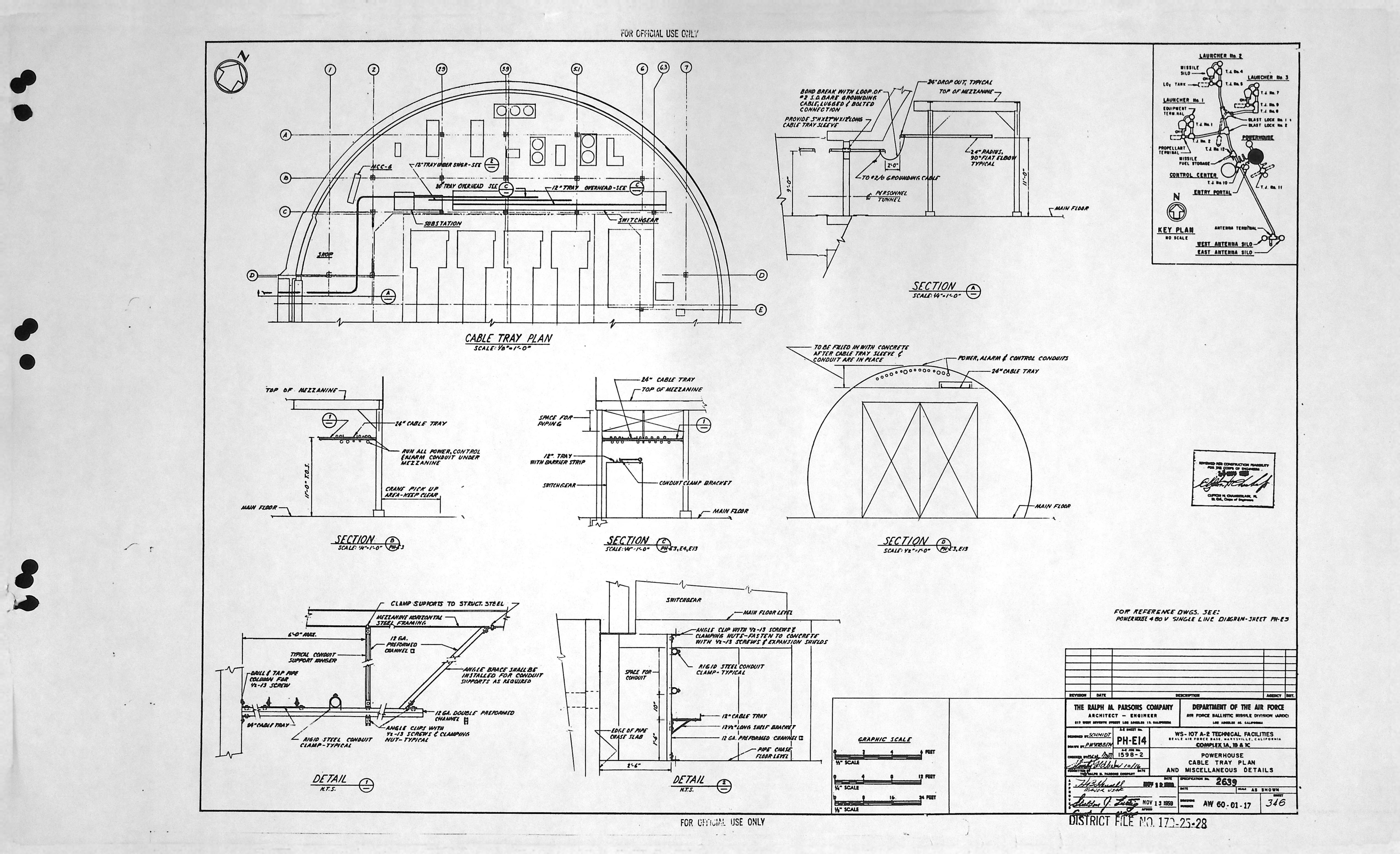
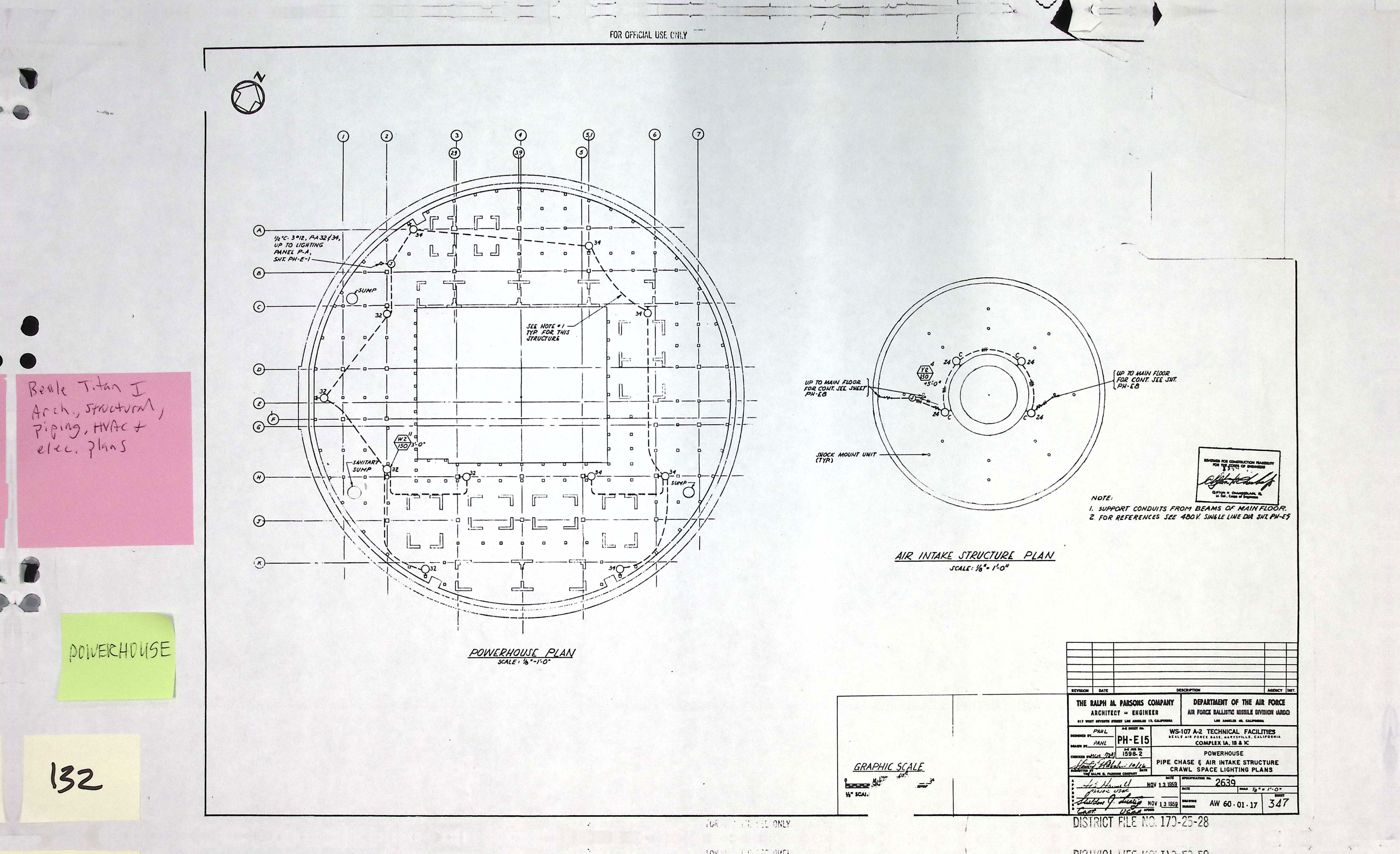
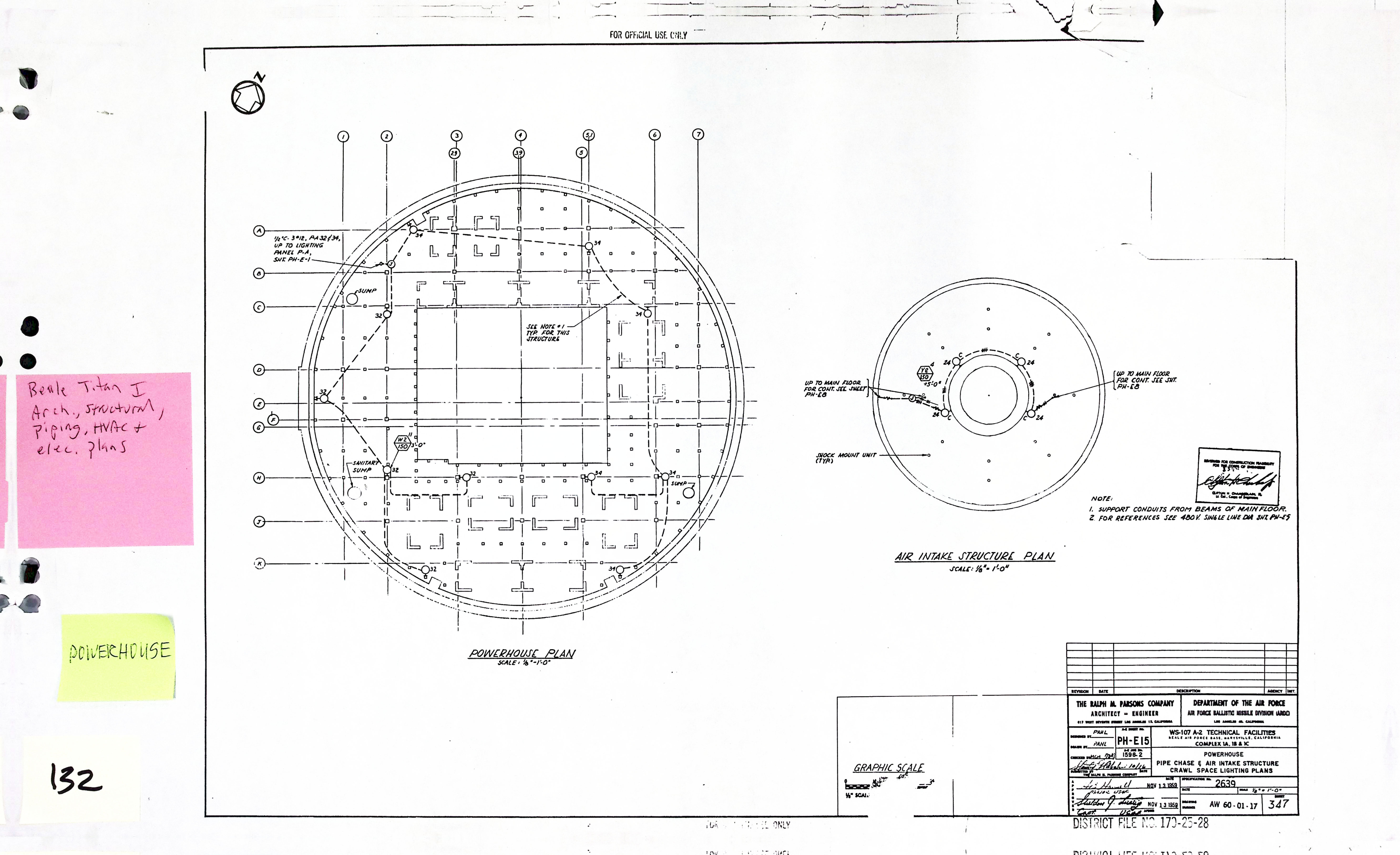
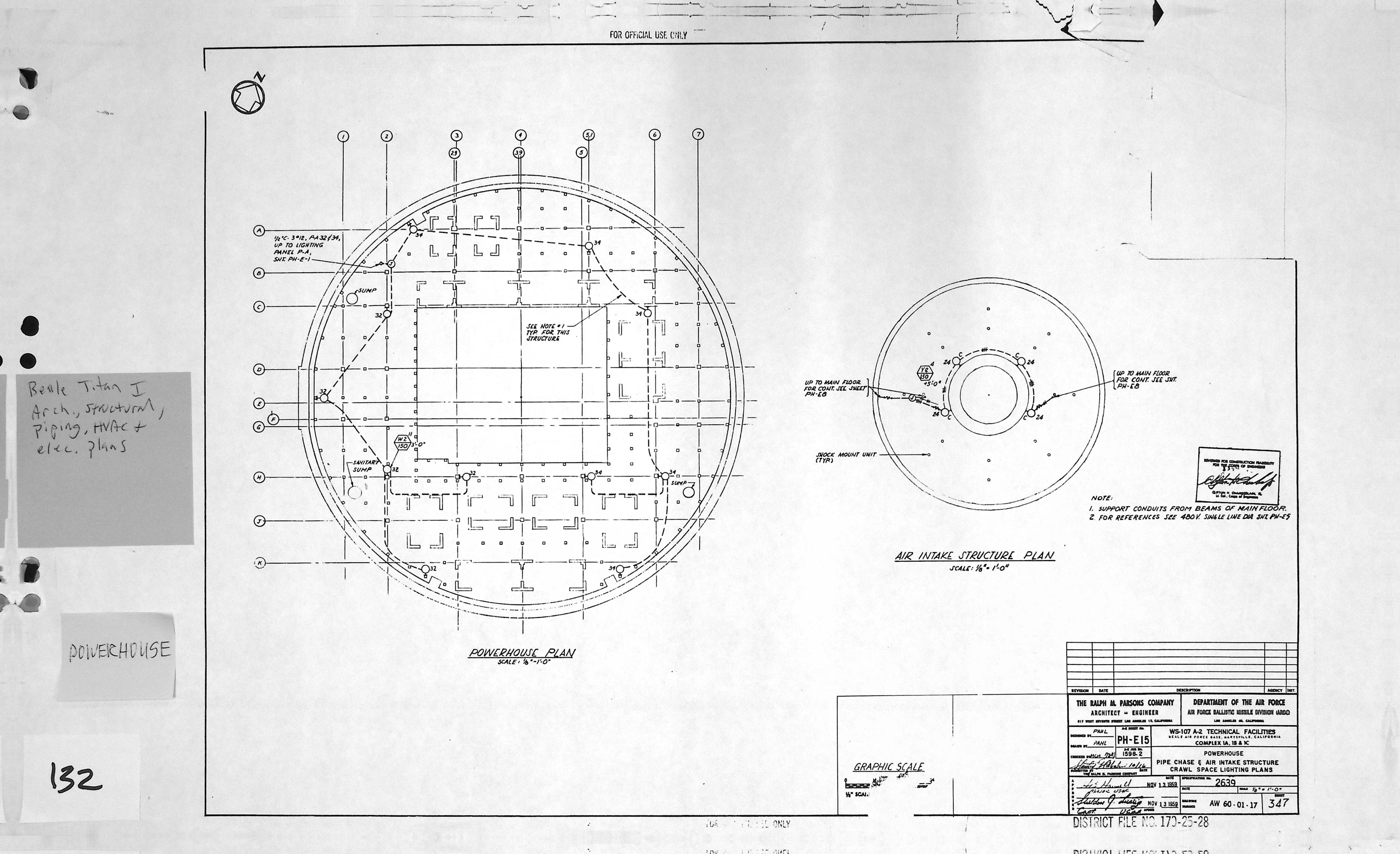
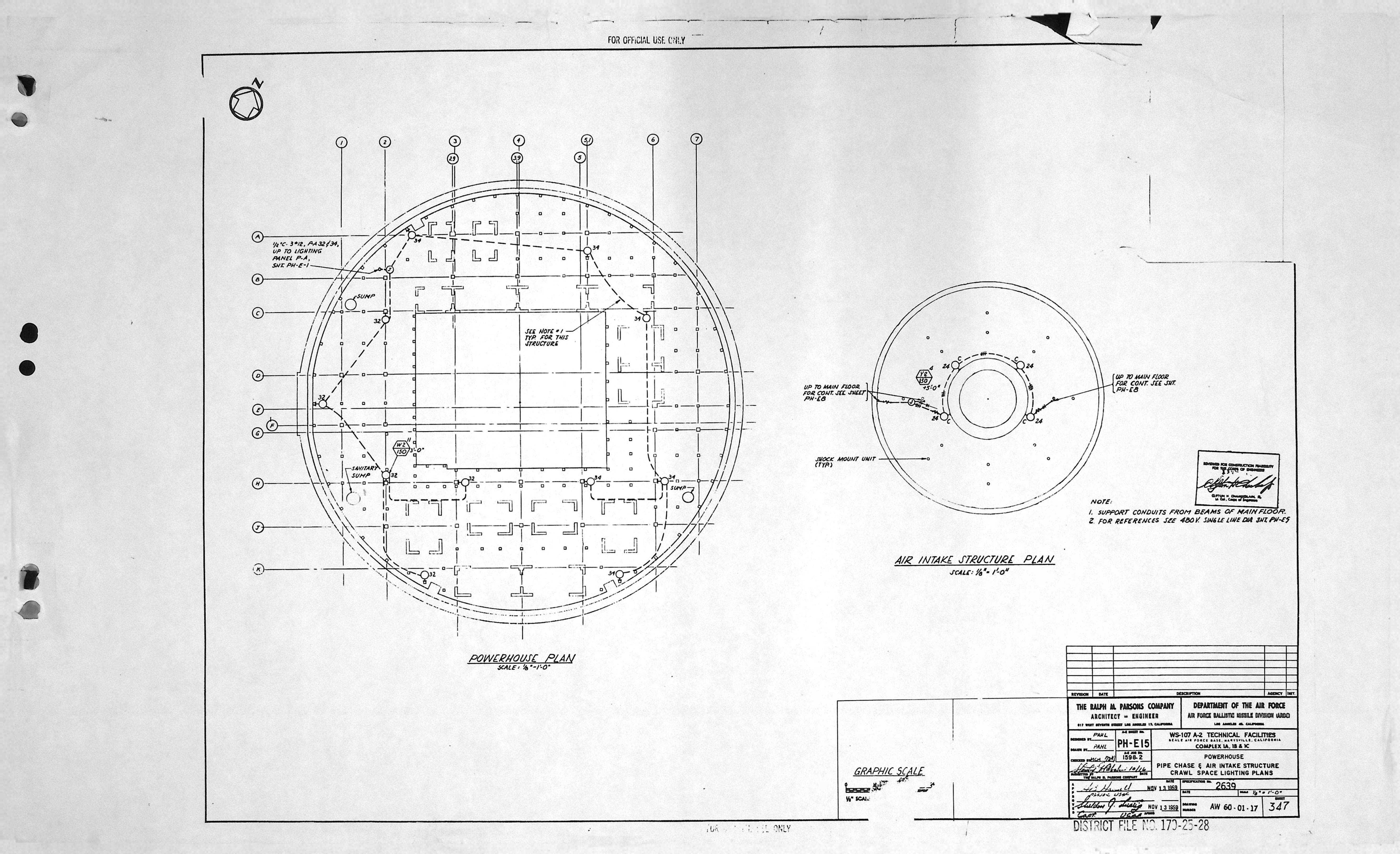
| PH-E15 | CABLE TRAY PLAN & MISC. DETAILS |
| PH-E15 | CABLE TRAY PLAN & MISC. DETAILS * |
| PH-E15 | CABLE TRAY PLAN & MISC. DETAILS * |
| PH-E15 | CABLE TRAY PLAN & MISC. DETAILS * |
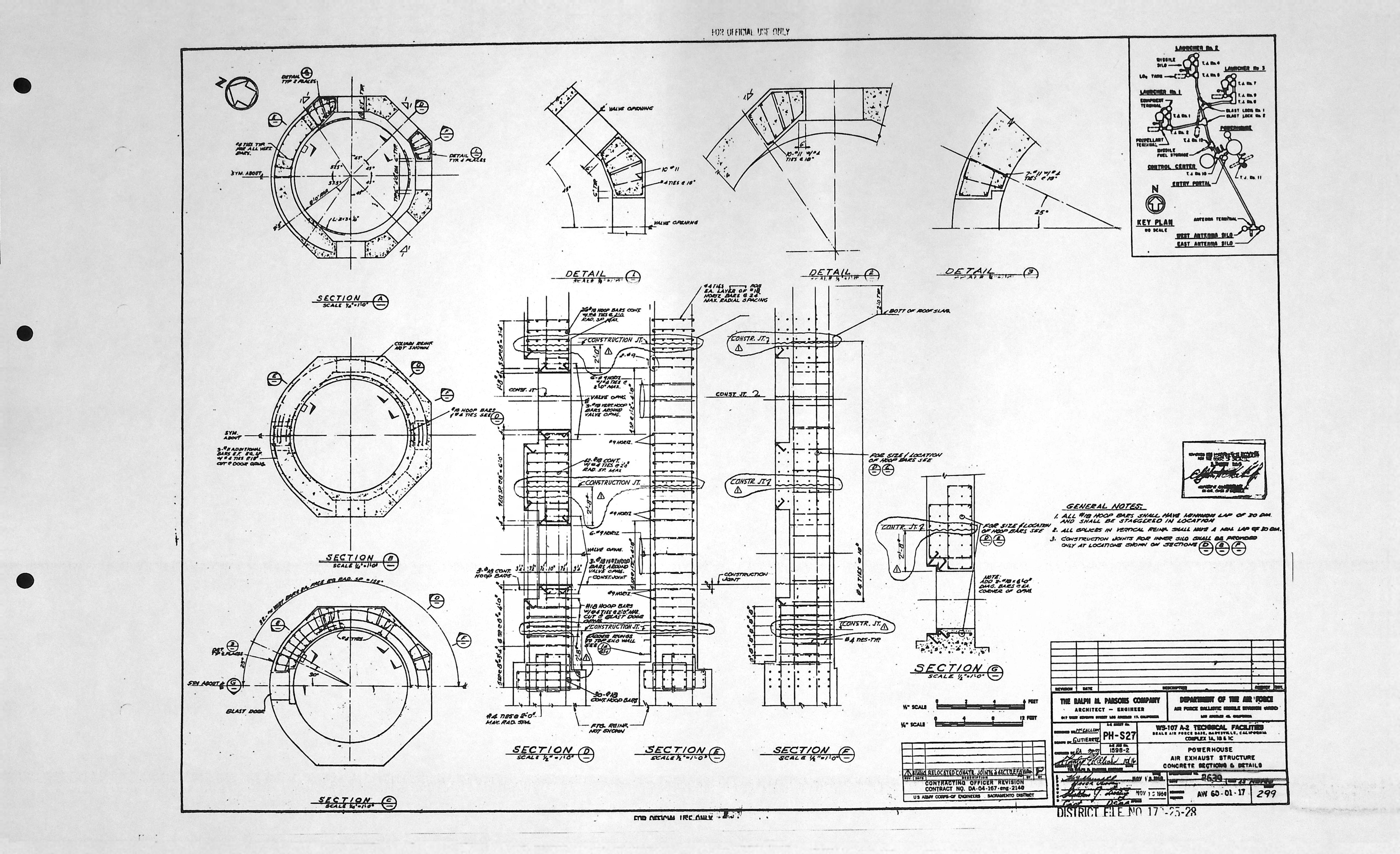
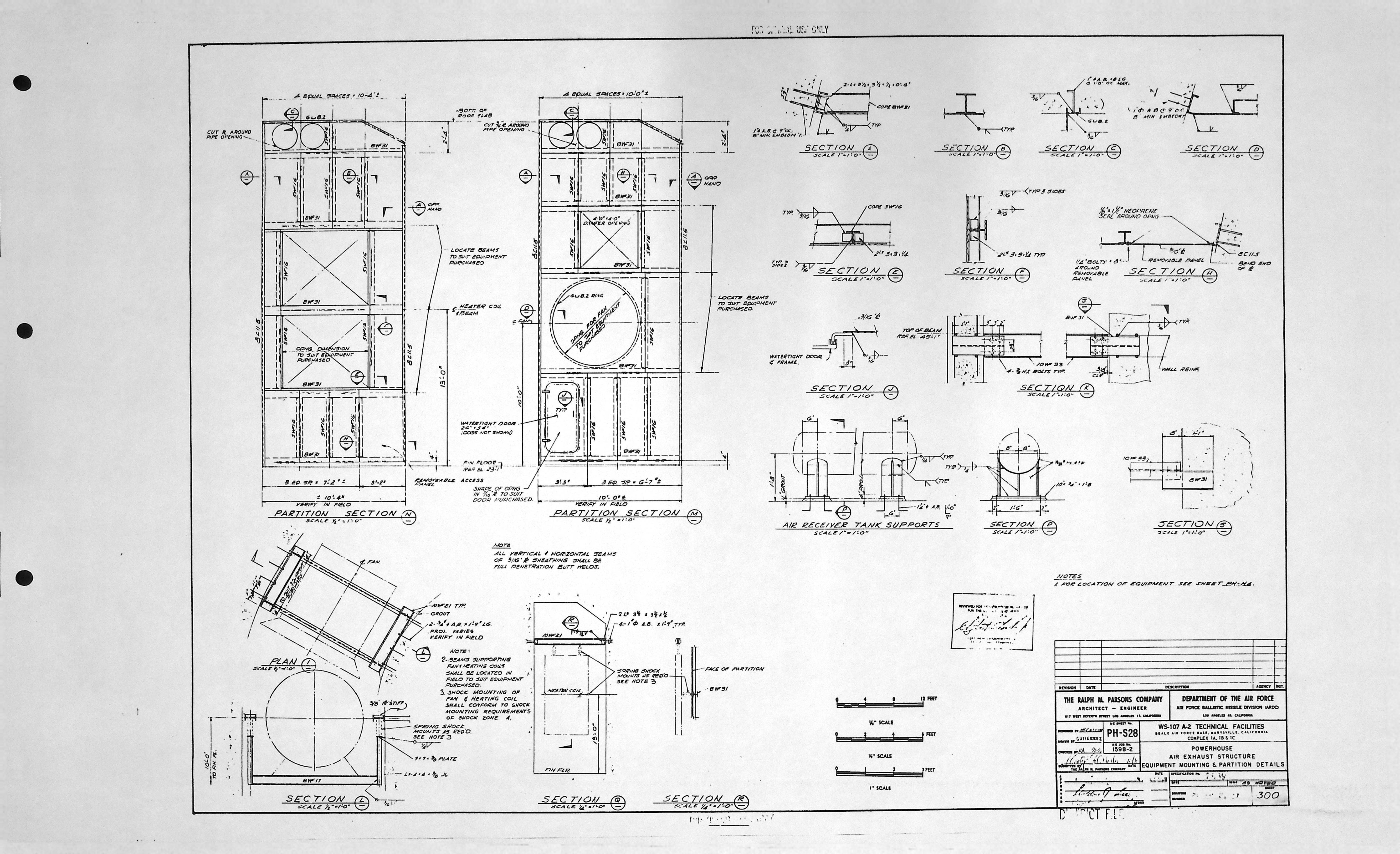
Power House - HVAC drawings (5)
| Drawing Number | Description |
|---|---|
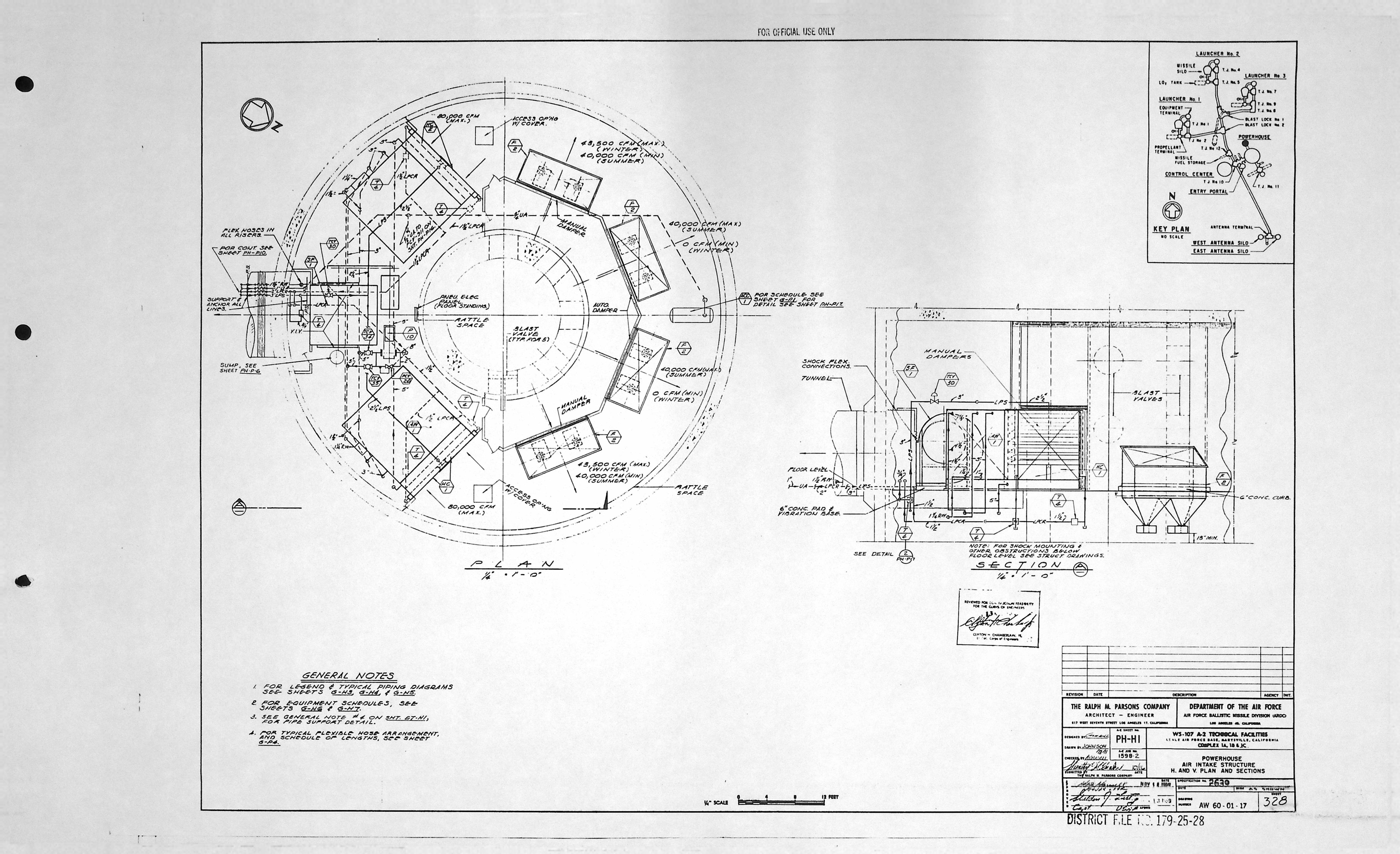
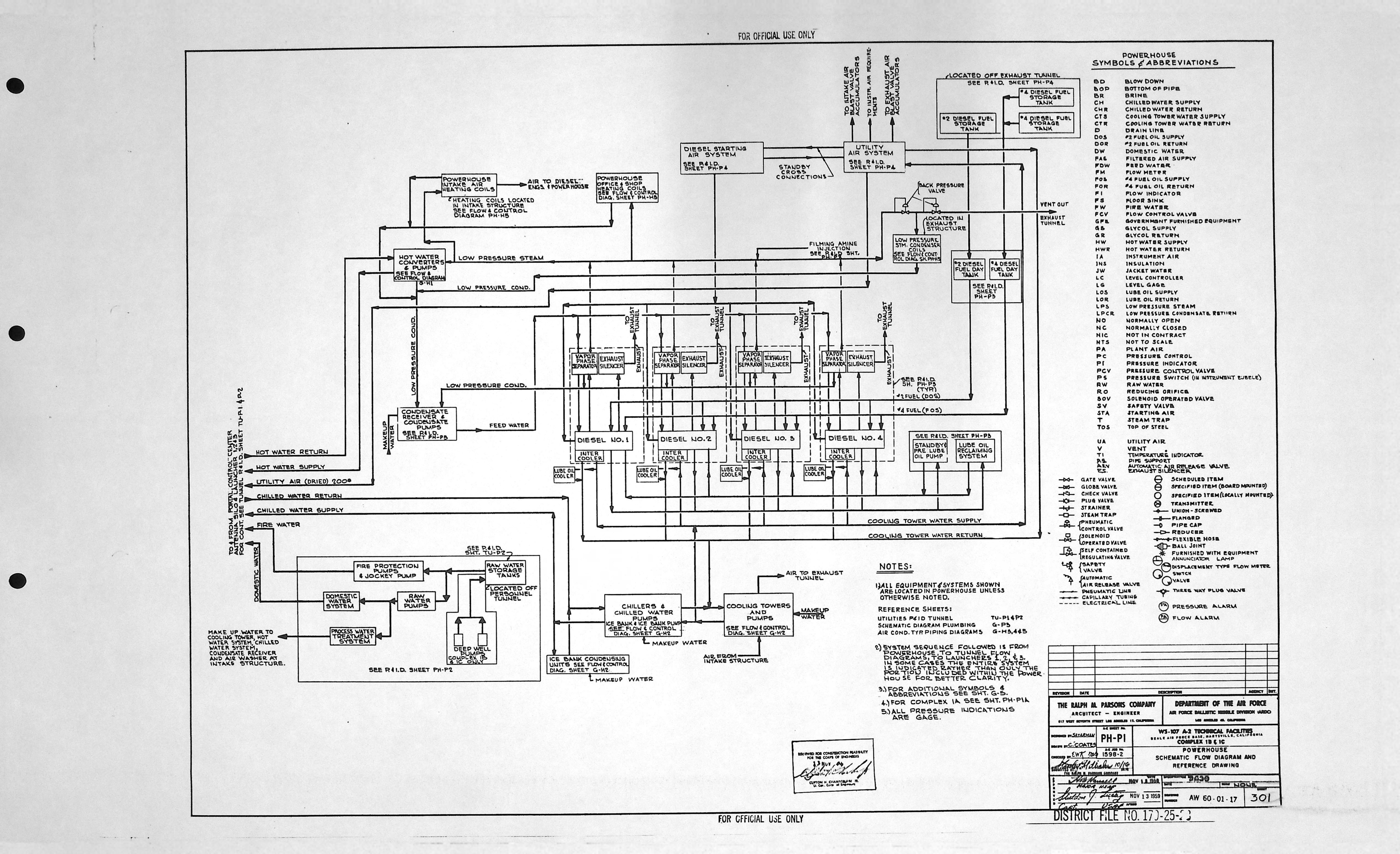
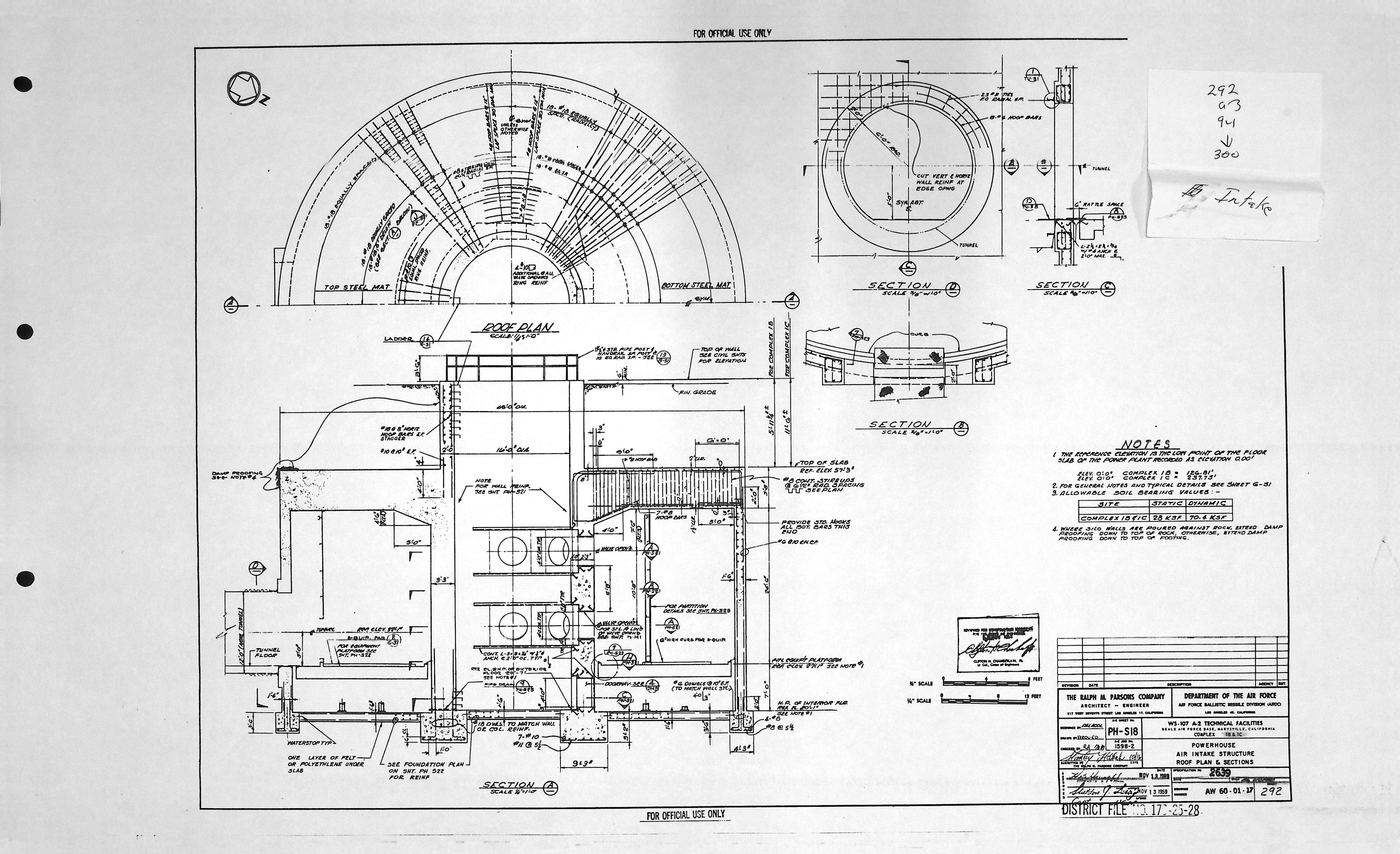
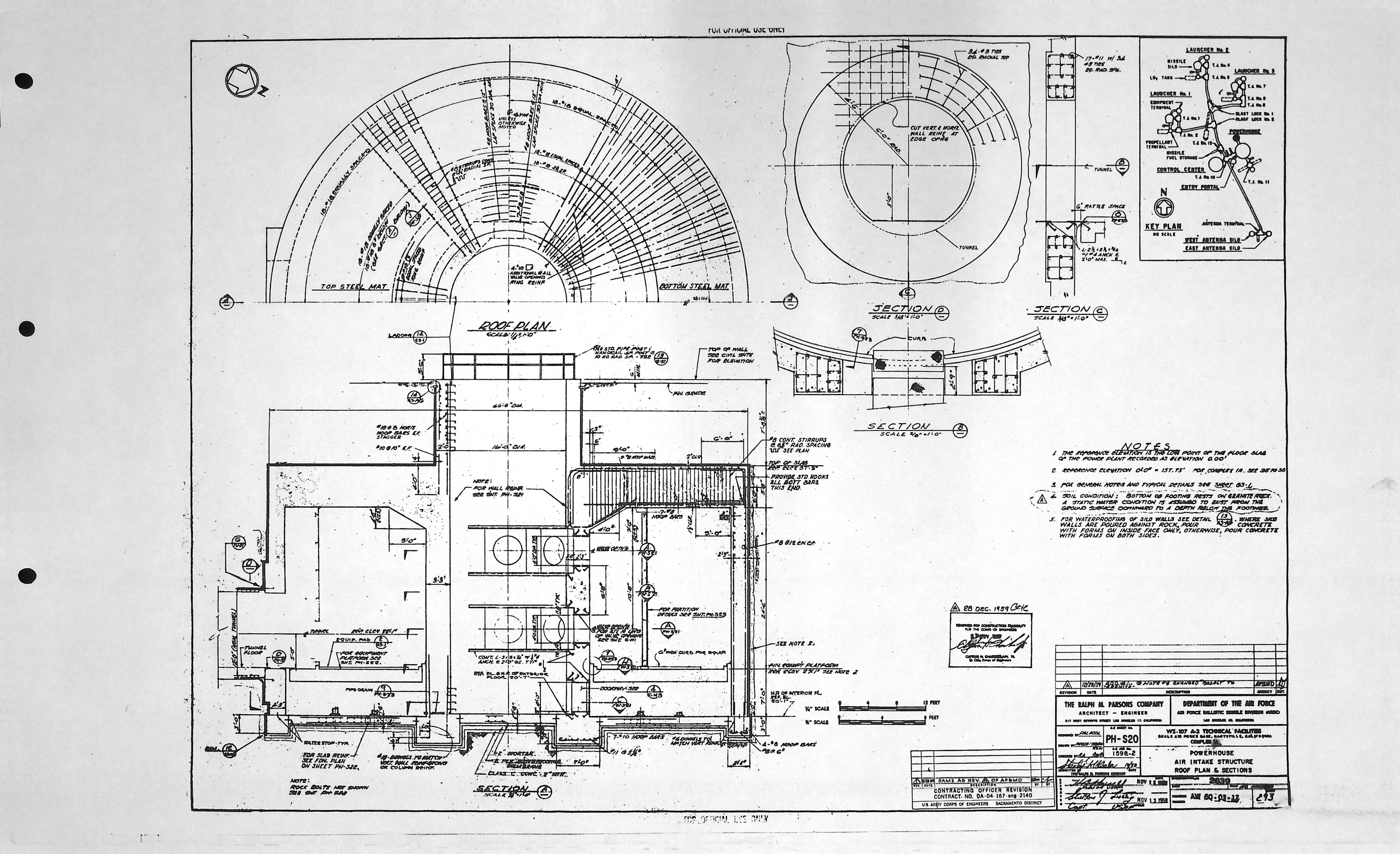
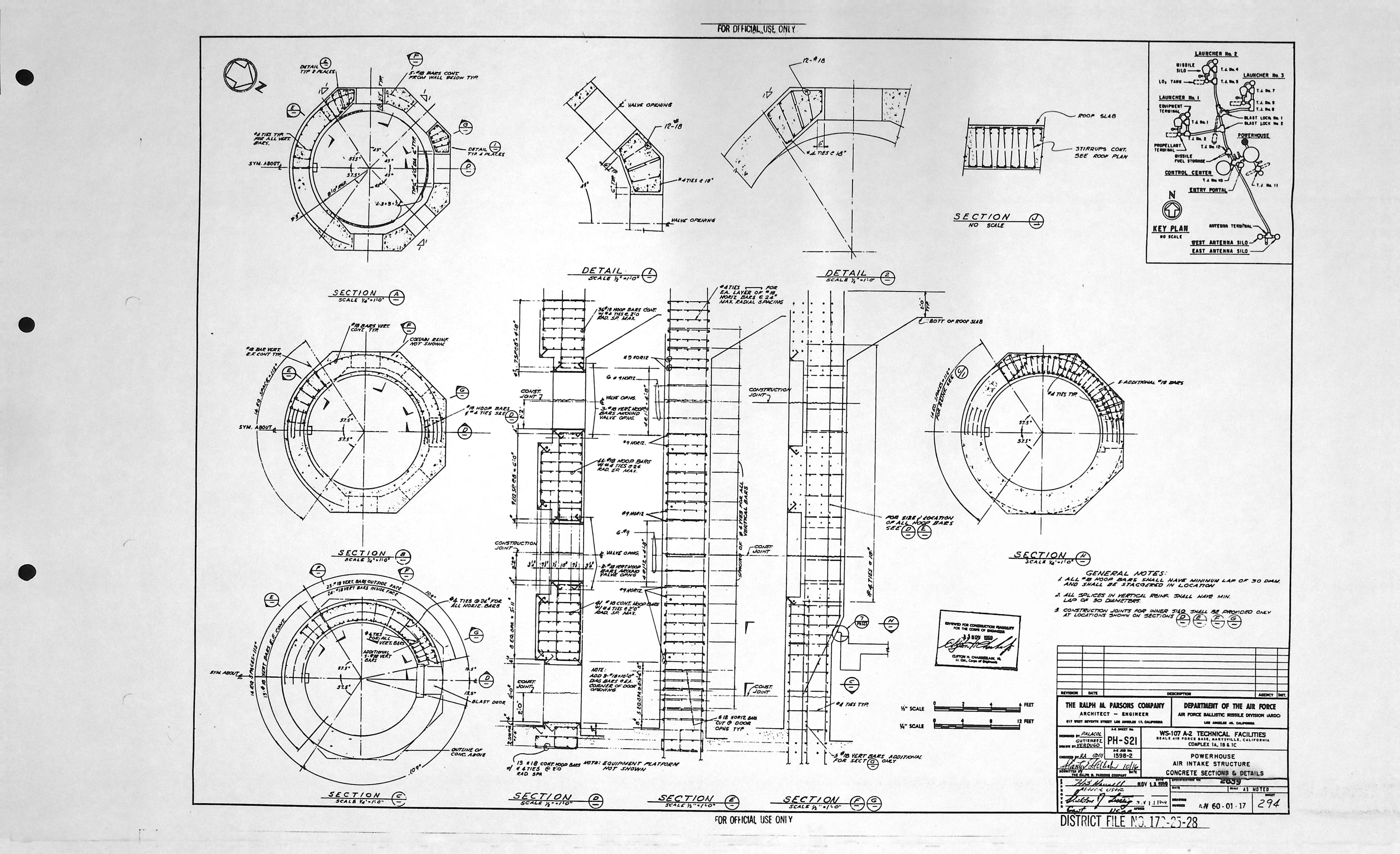
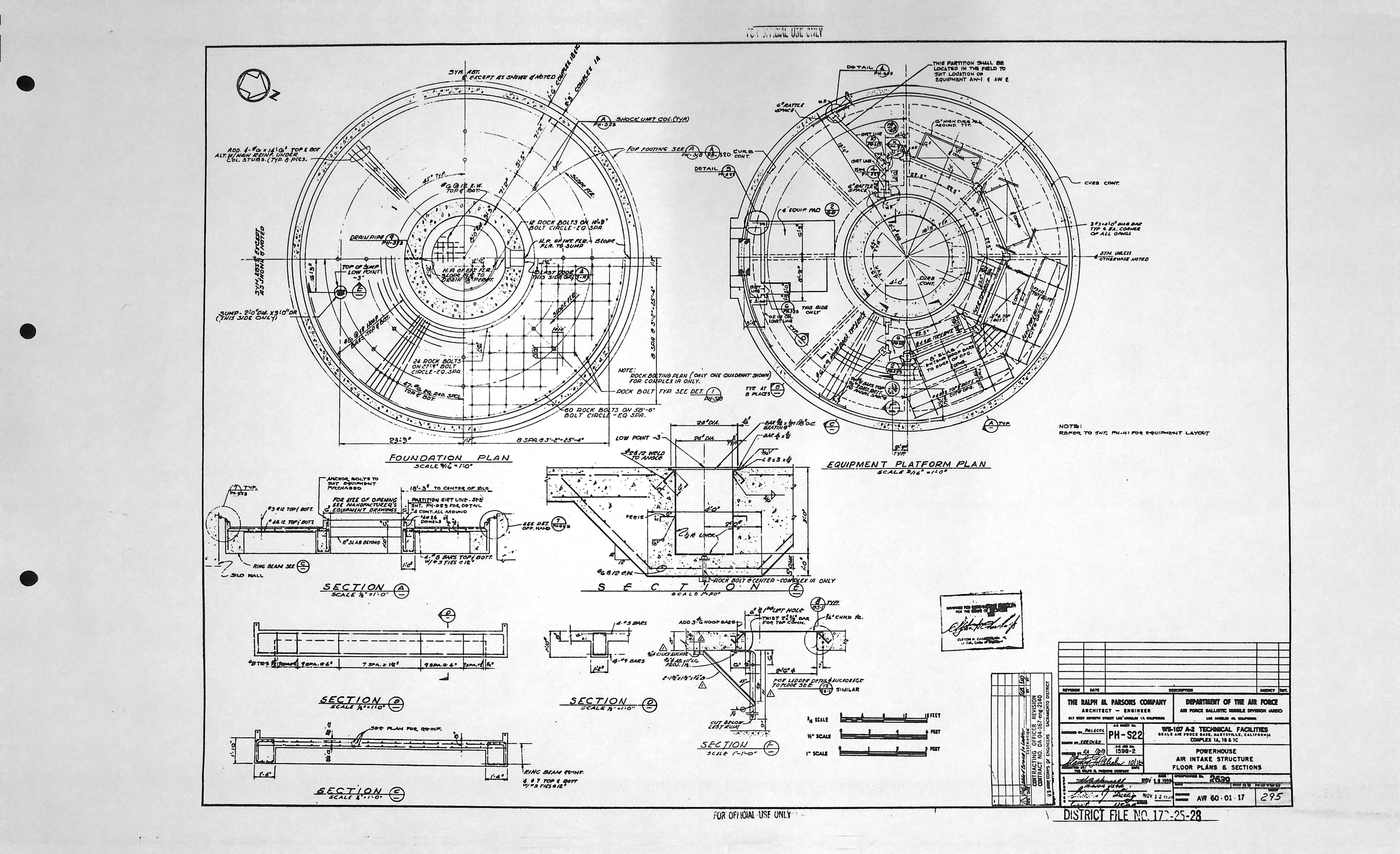
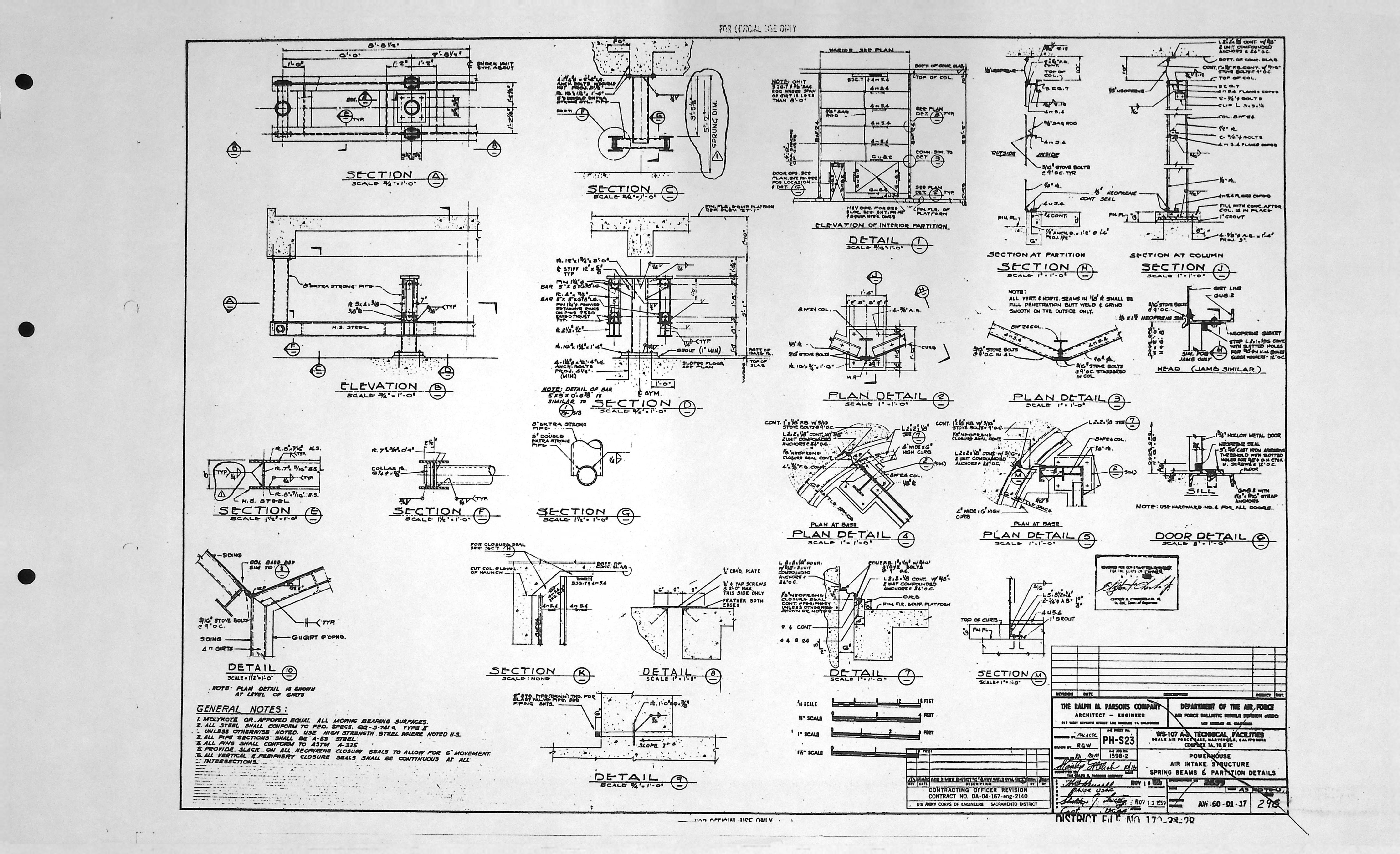
| PH-H1 | AIR INTAKE STRUCTURE H. & V. PLAN & SECTIONS |
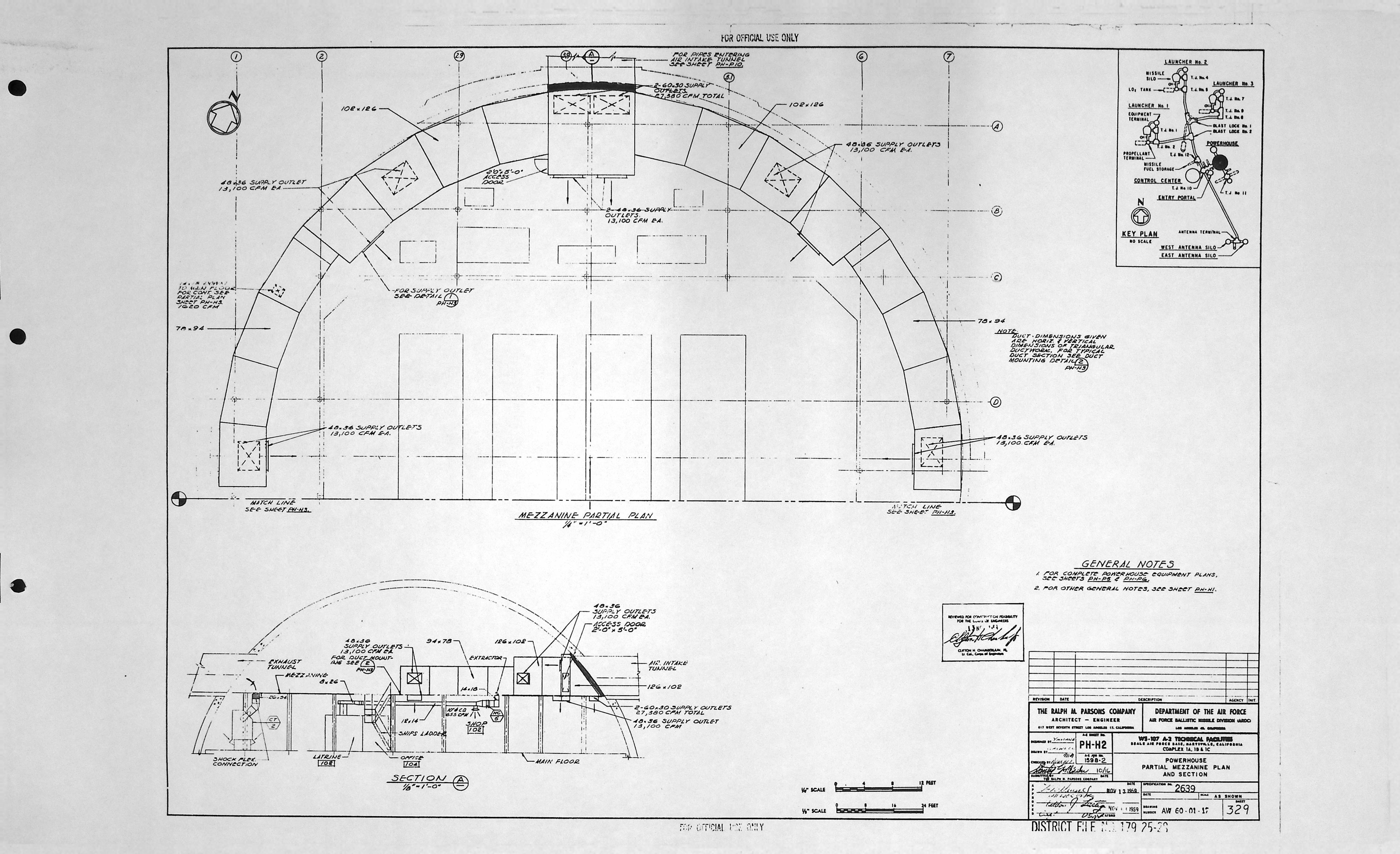
| PH-H2 | PARTIAL MEZZANINE PLAN & SECTION |
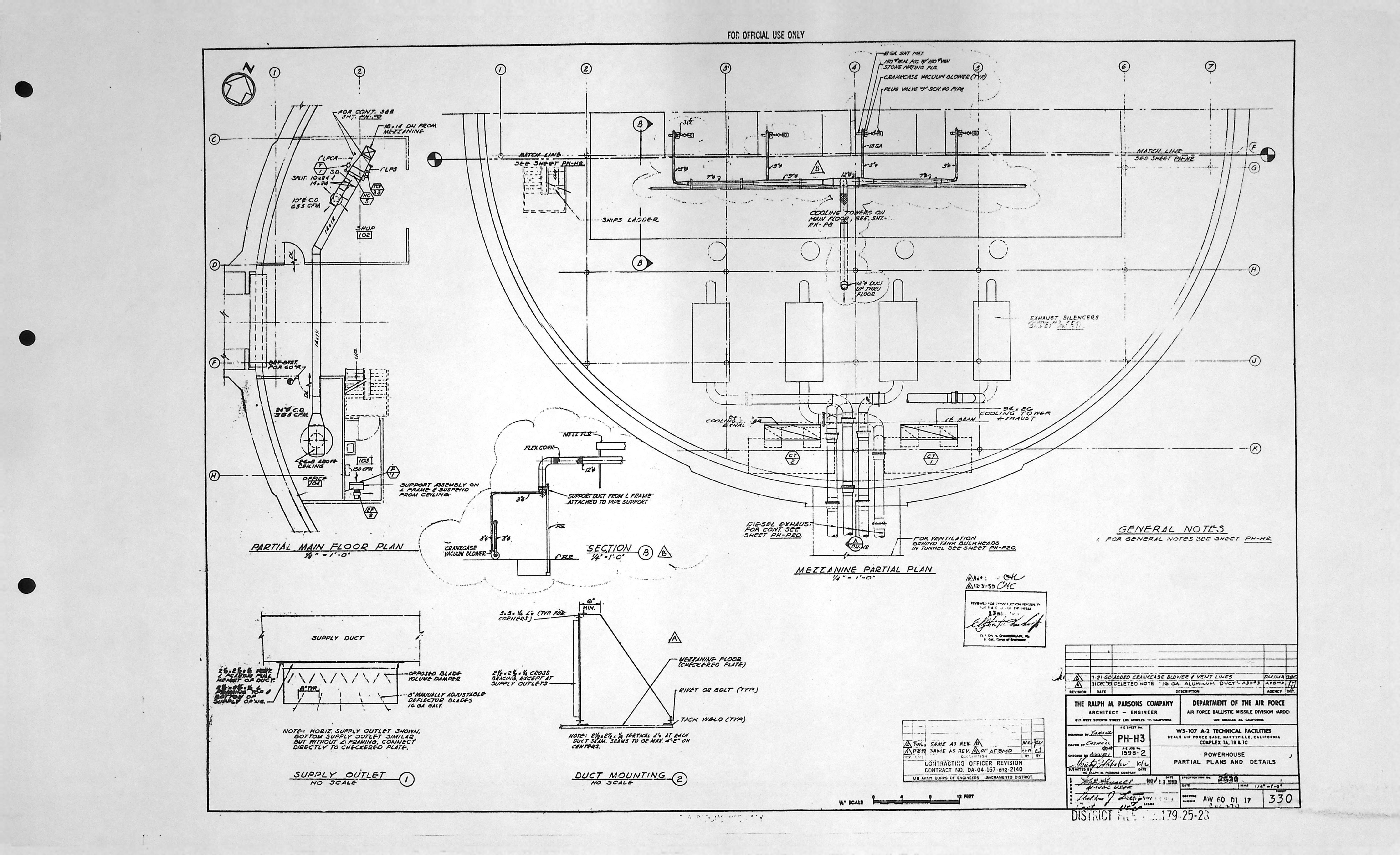
| PH-H3 | PARTIAL PLANS & DETAILS |
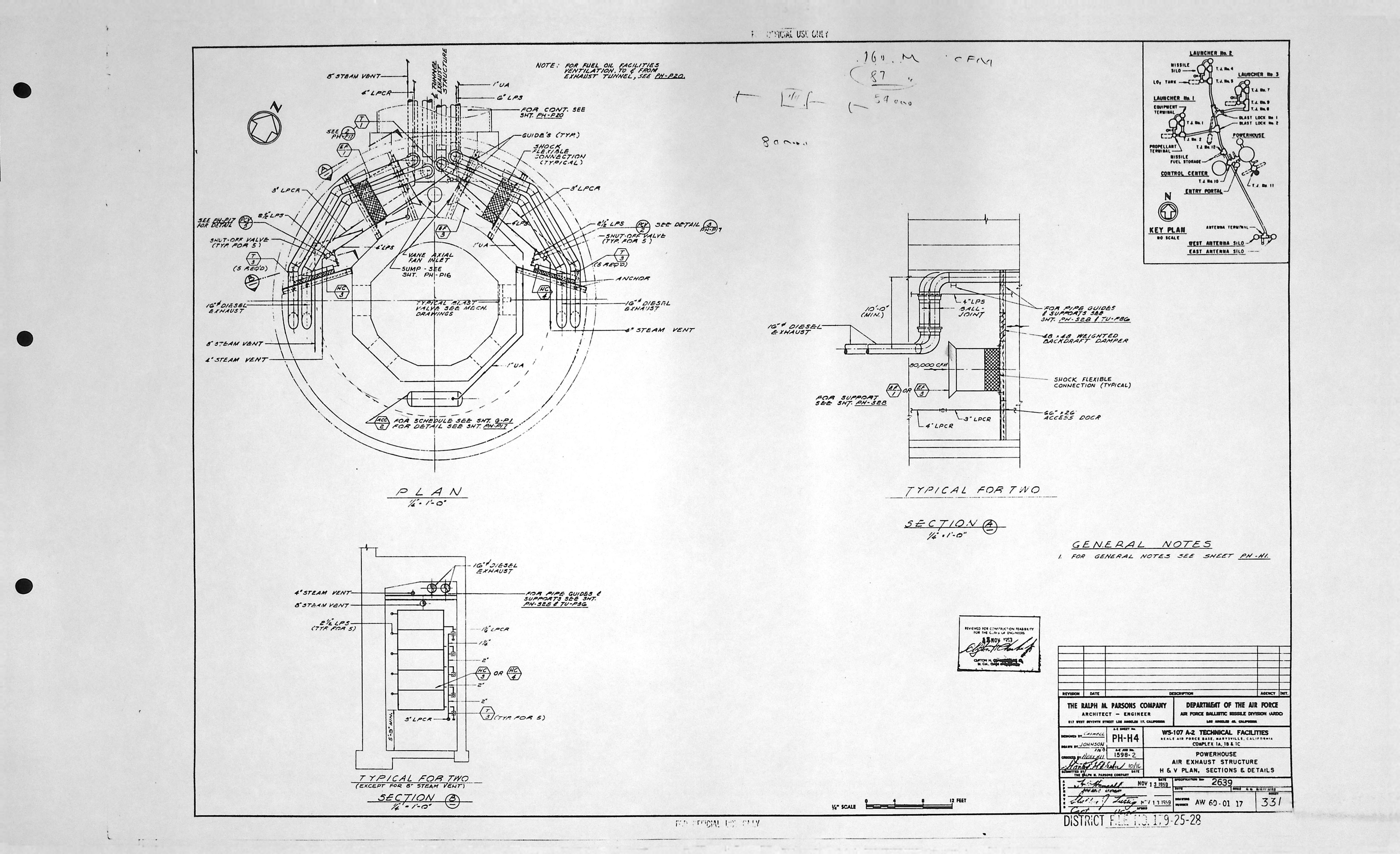
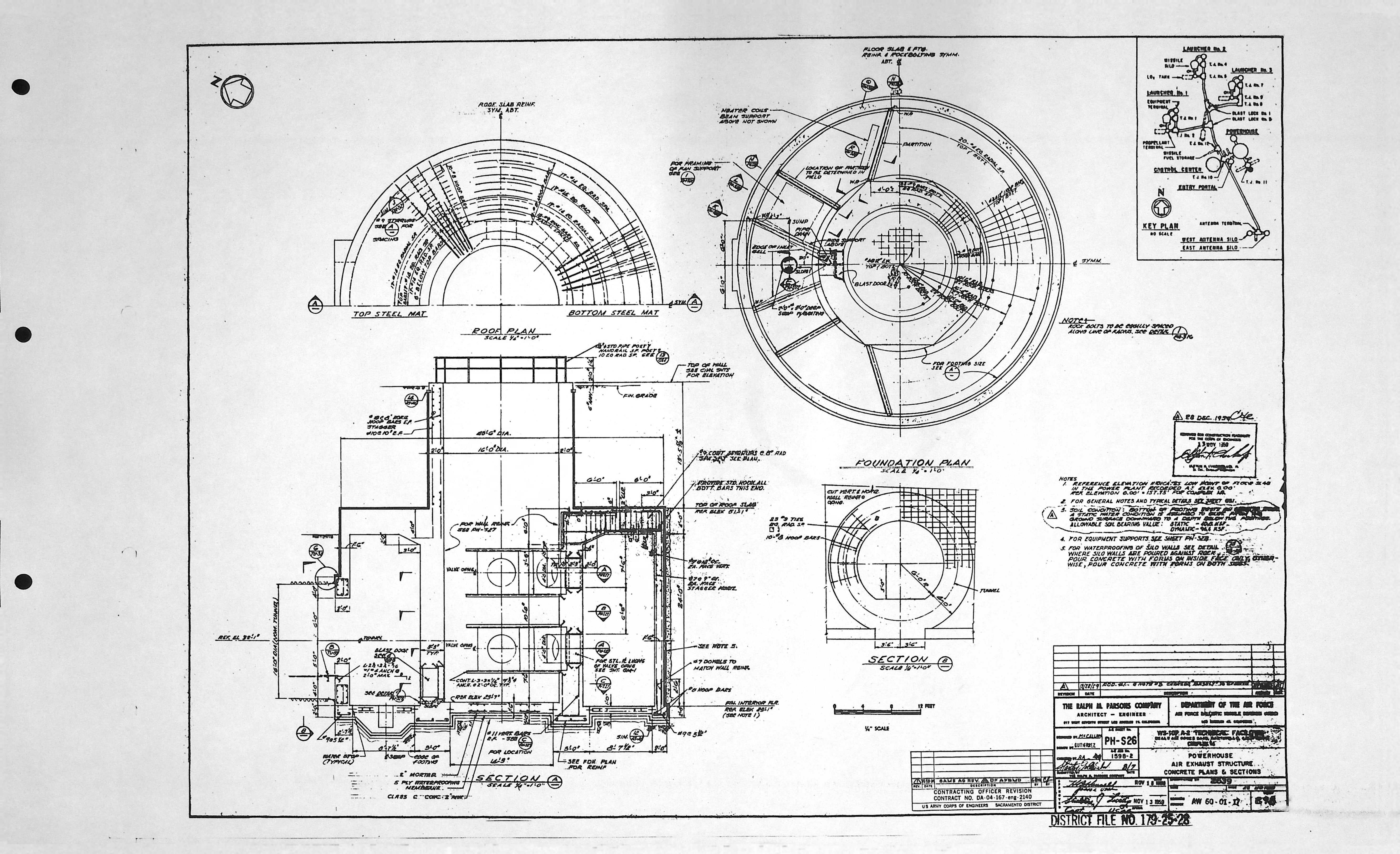
| PH-H4 | AIR EXHAUST STRUCTURE H & V PLAN, SECTIONS & DETAILS |
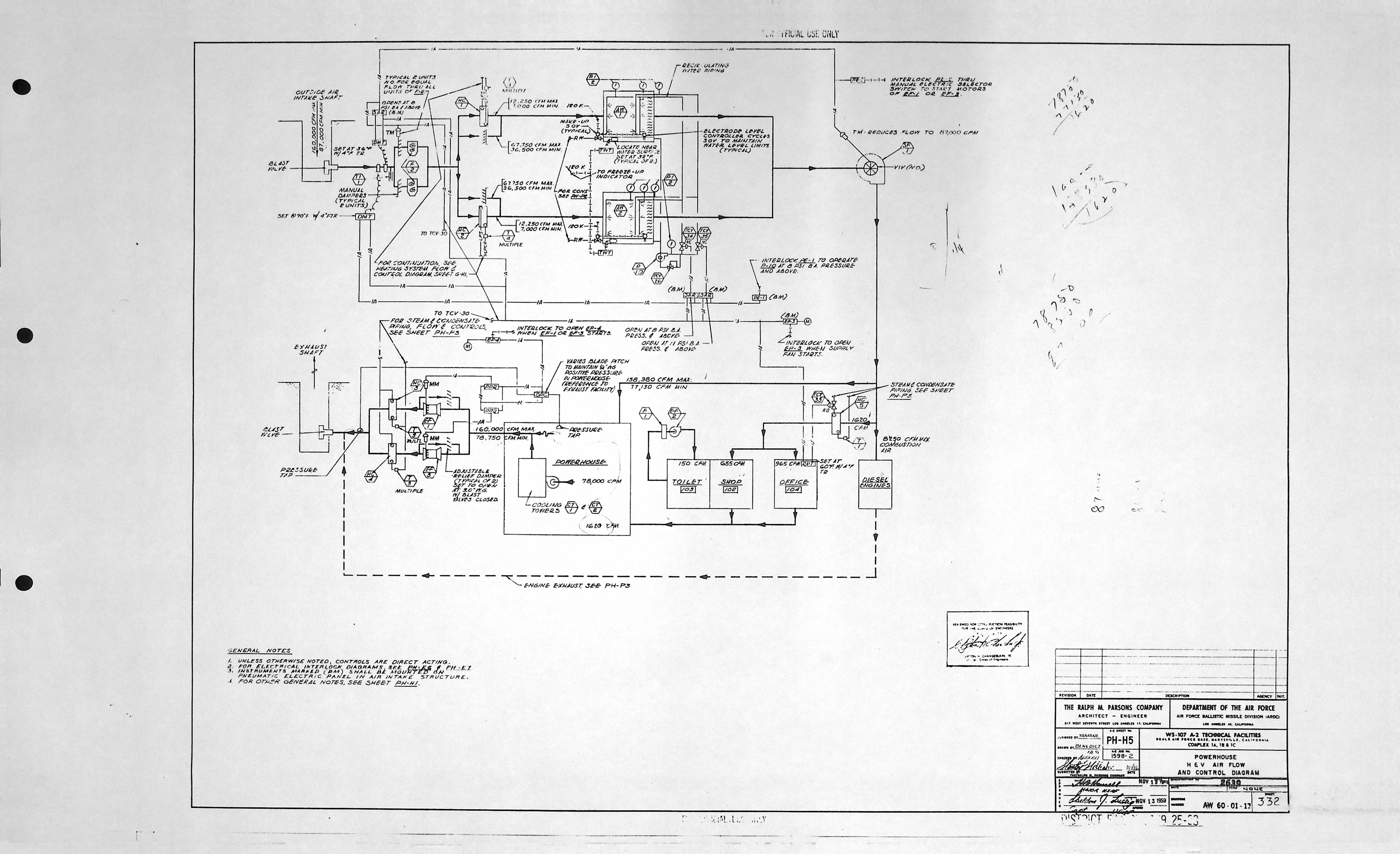
| PH-H5 | H & V AIR FLOW & CONTROL DIAGRAM |
Power House - Mechanical drawings (0)
| Drawing Number | Description |
|---|---|
| -- | N/A |