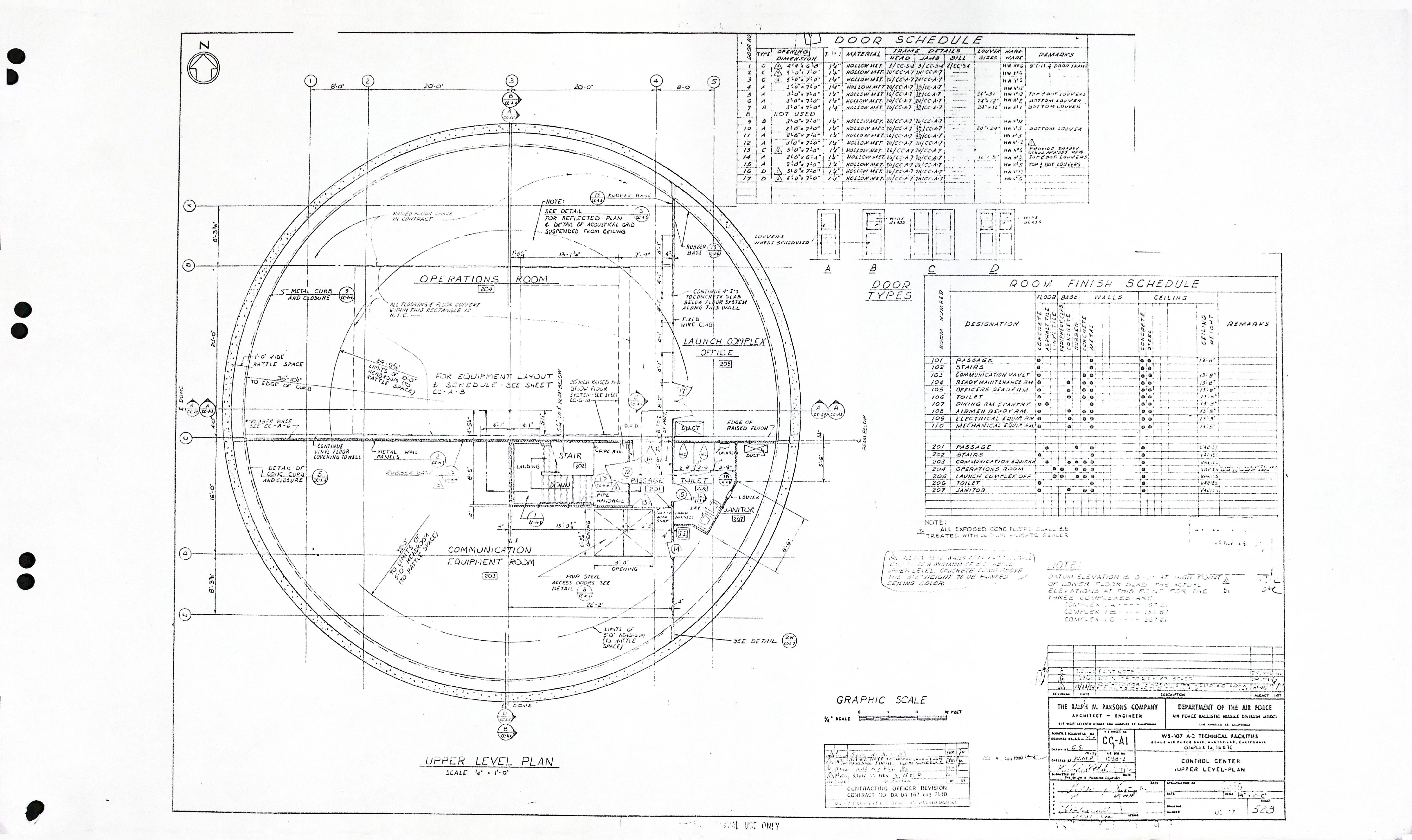
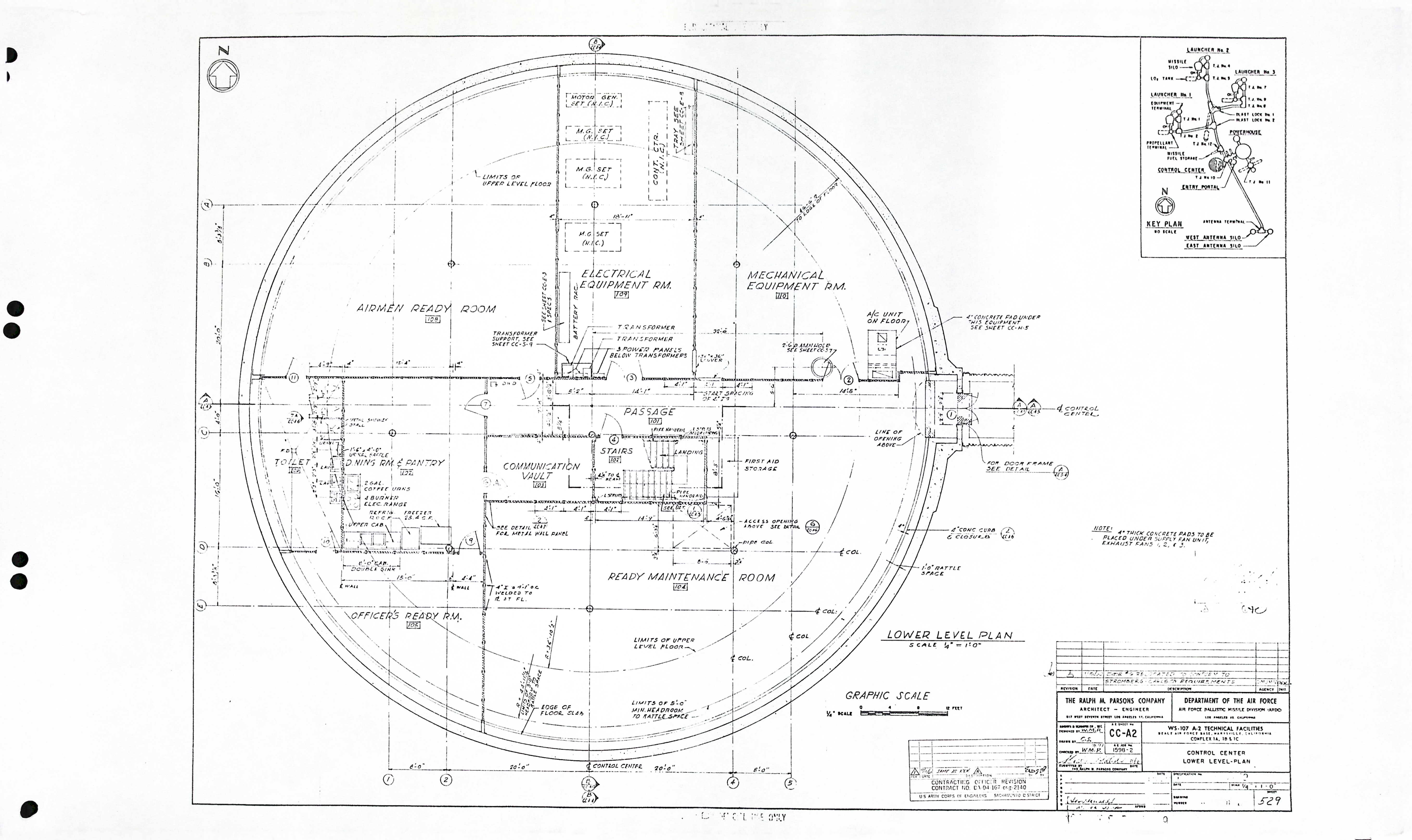
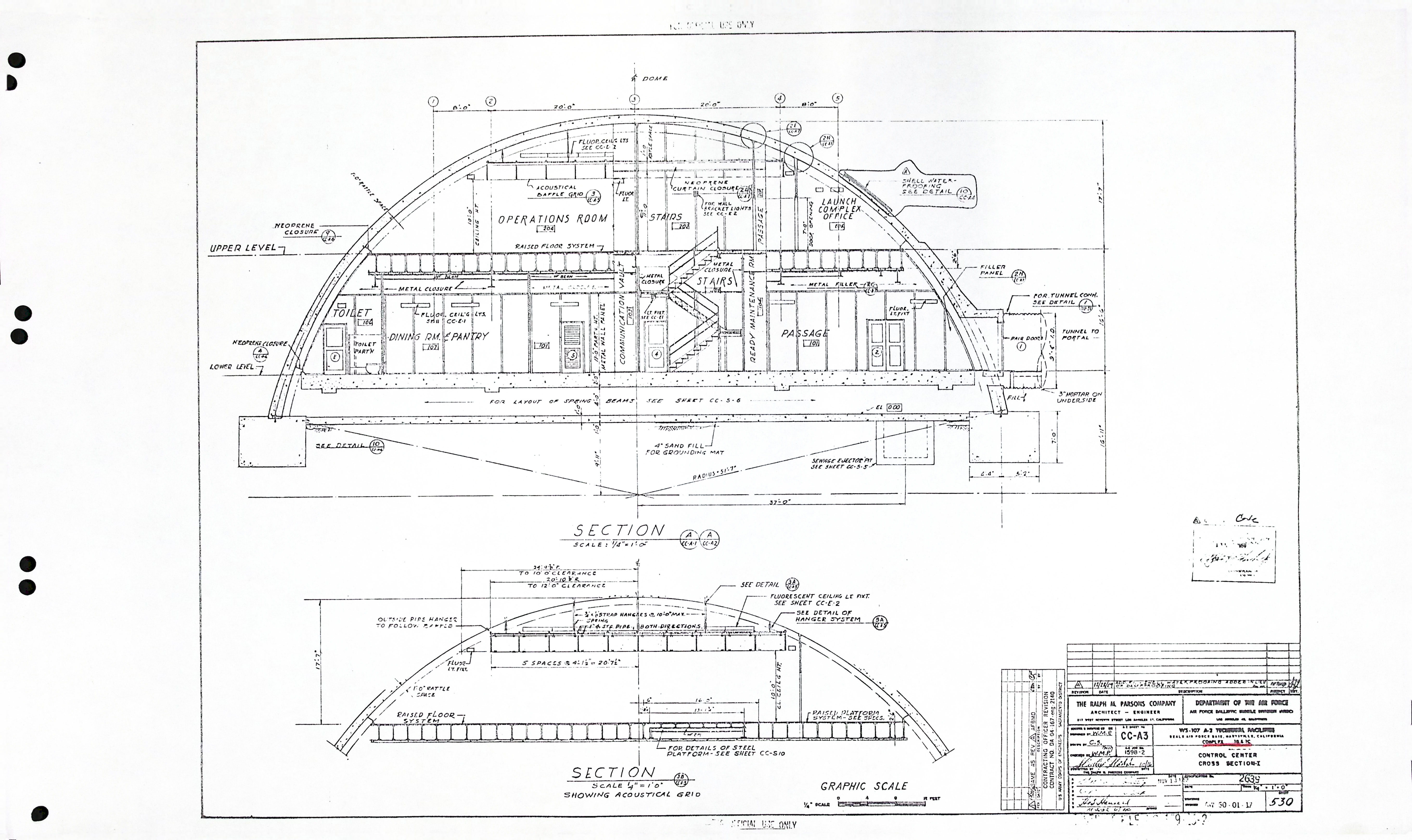
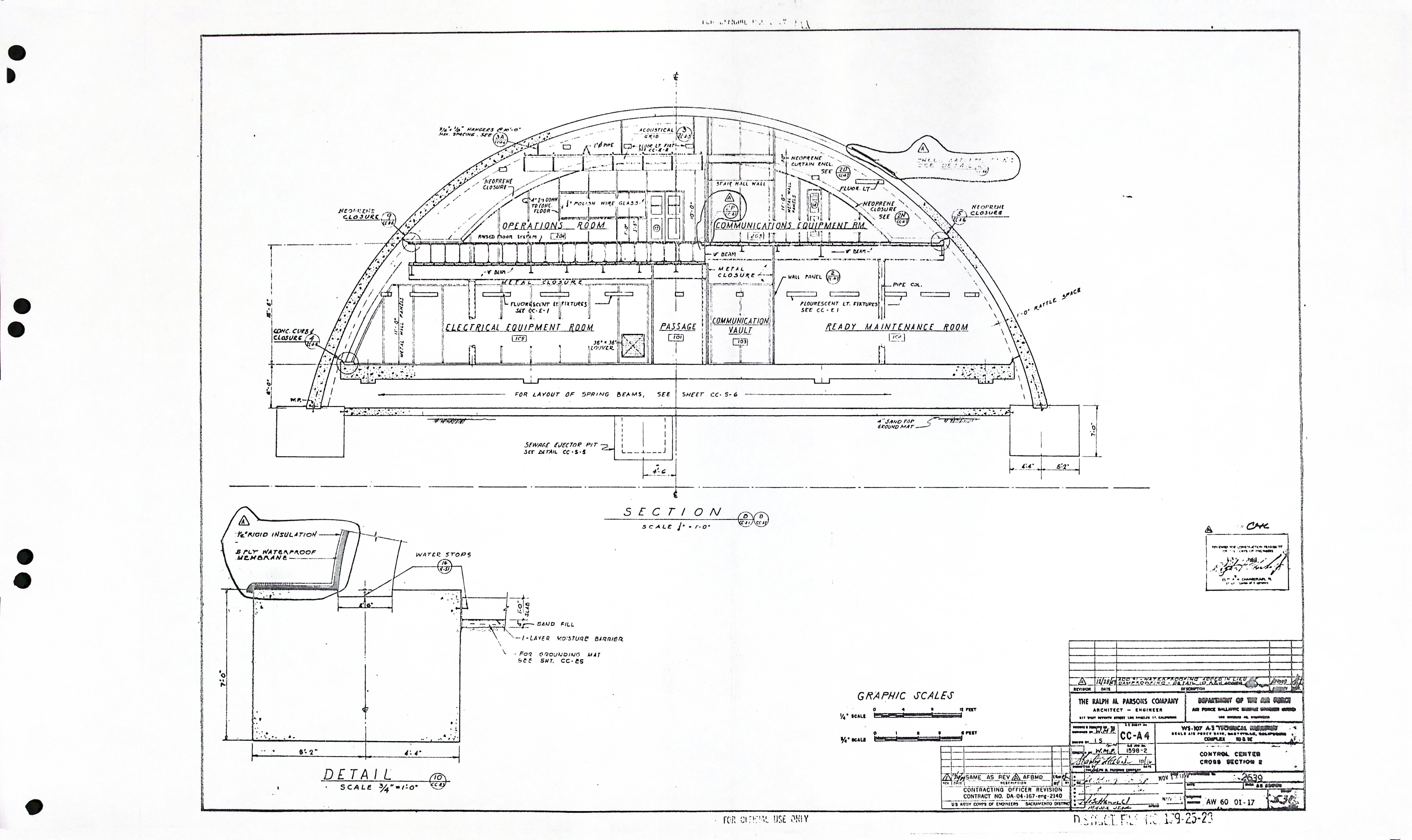
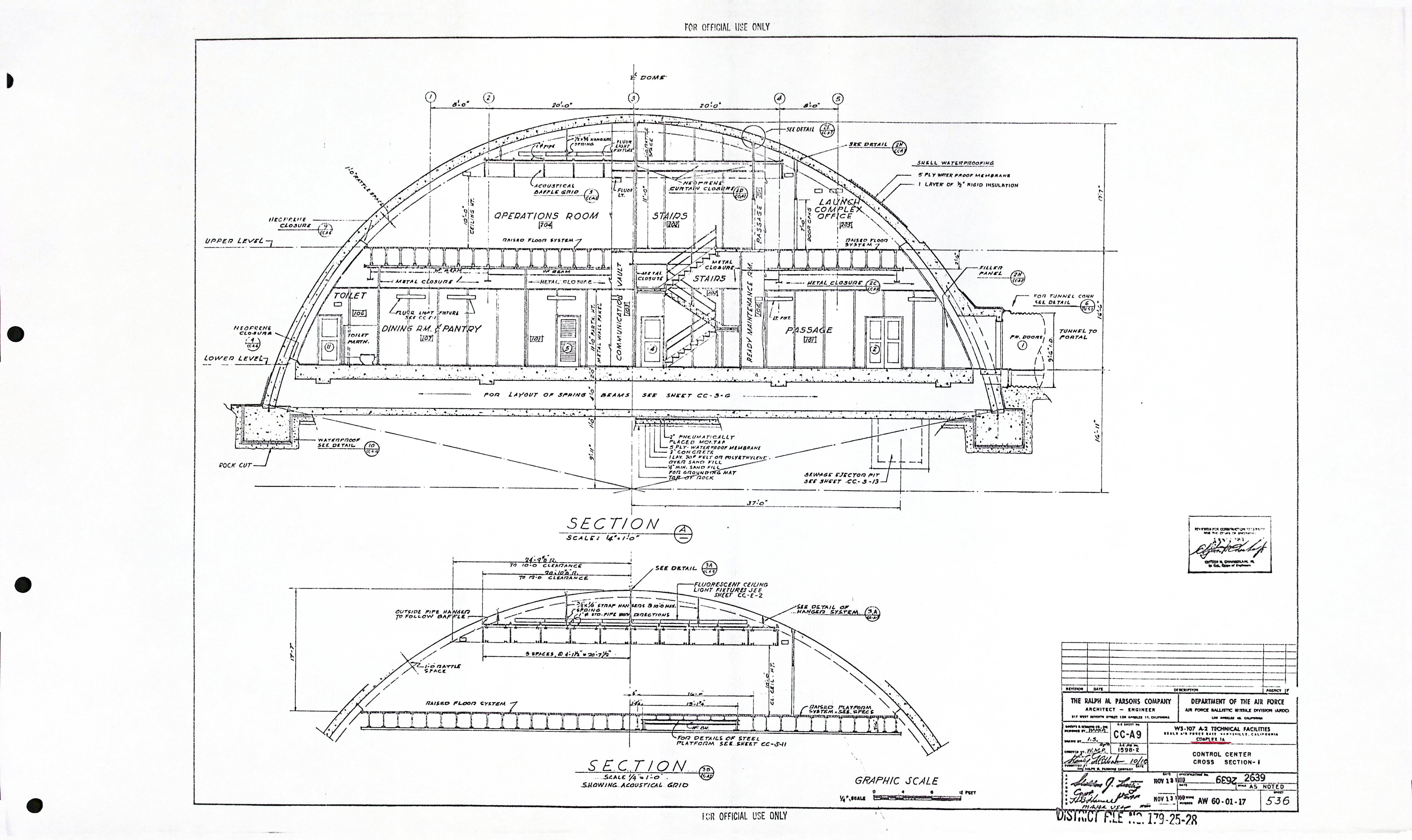
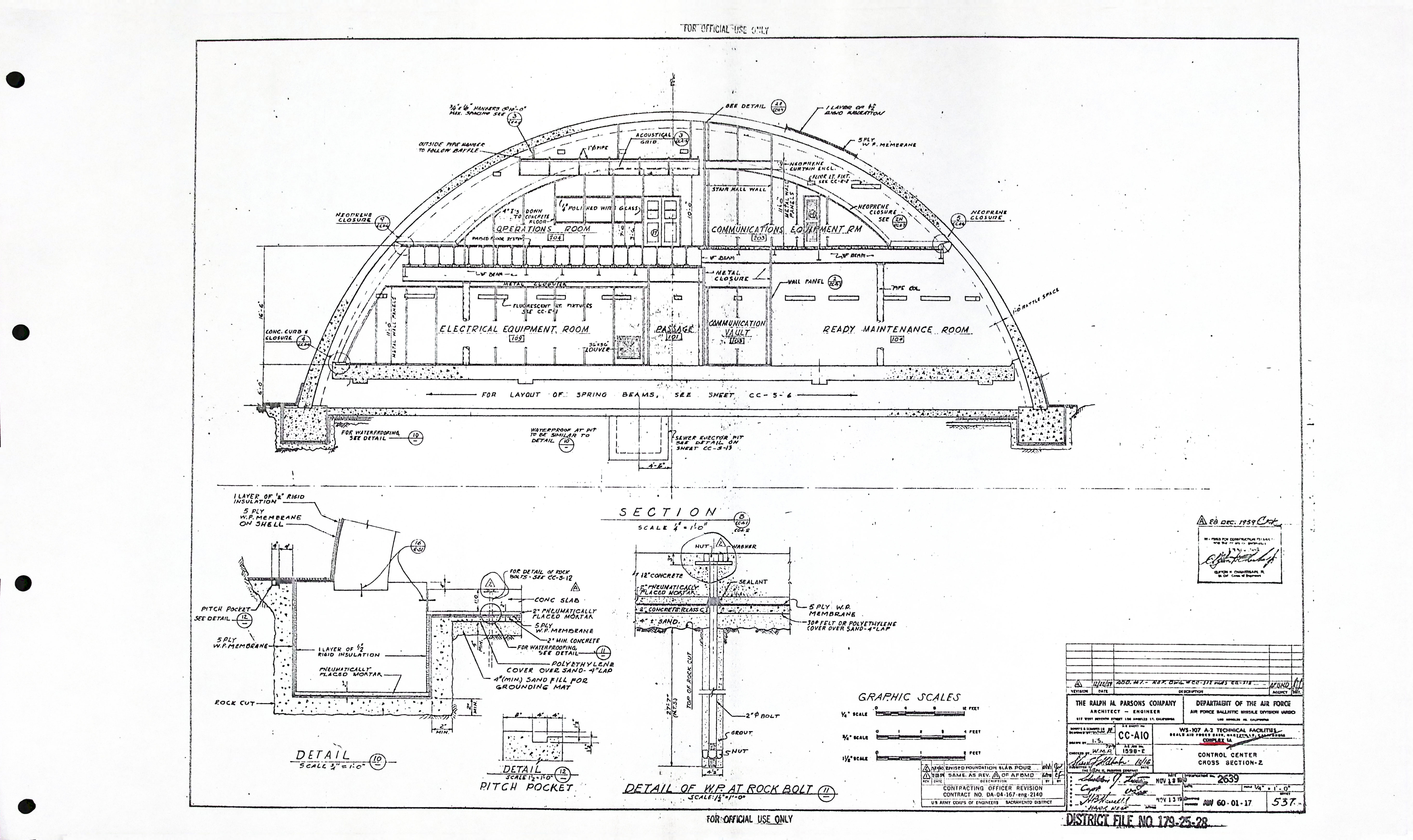
Control Center - Architectural drawings (10)
| Drawing Number | Description |
|---|---|
| CC-A1 | UPPER LEVEL - PLAN |
| CC-A2 | LOWER LEVEL - PLAN |
| CC-A3 | CROSS SECTION - I |
| CC-A4 | CROSS SECTION - 2 |
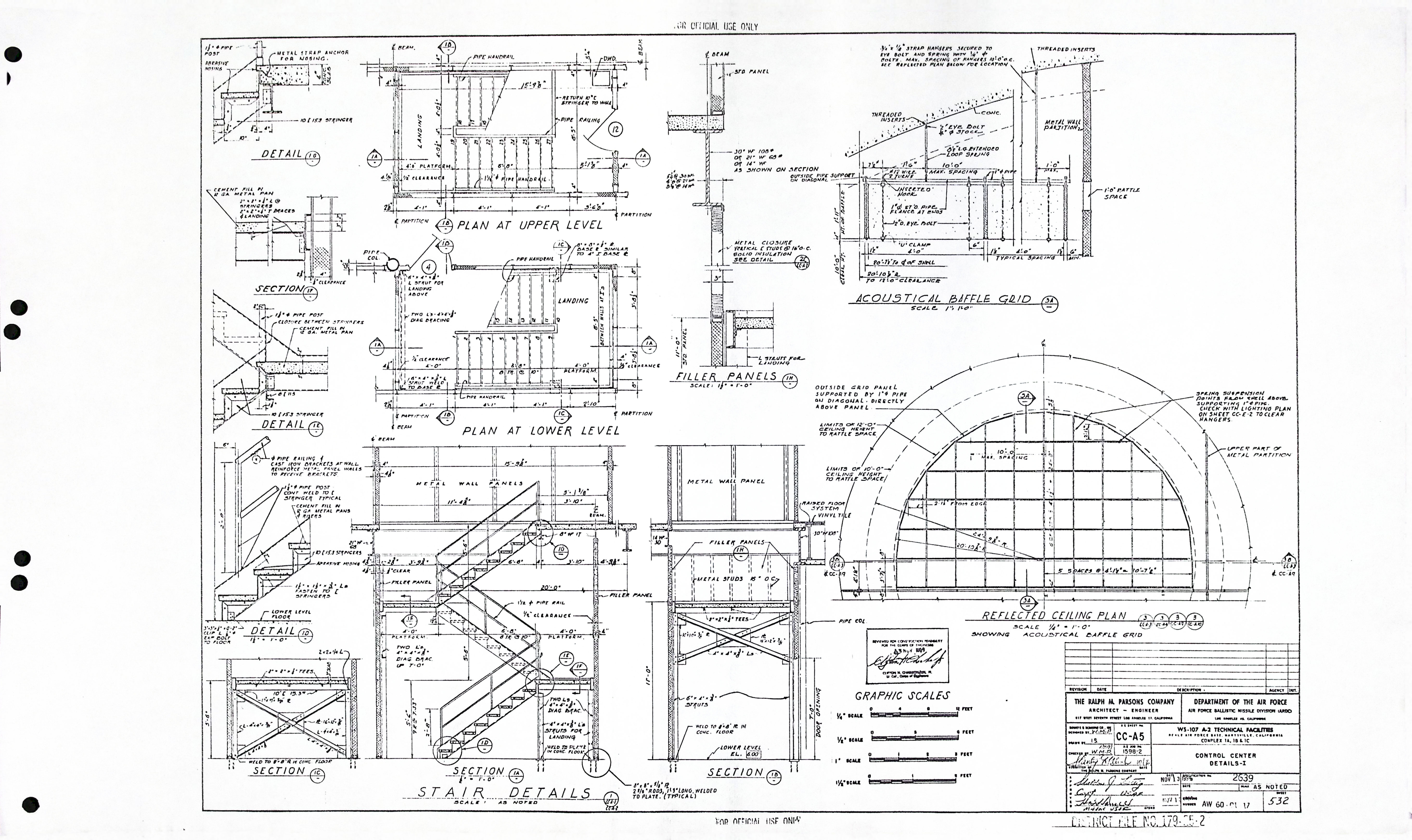
| CC-A5 | DETAILS - I |
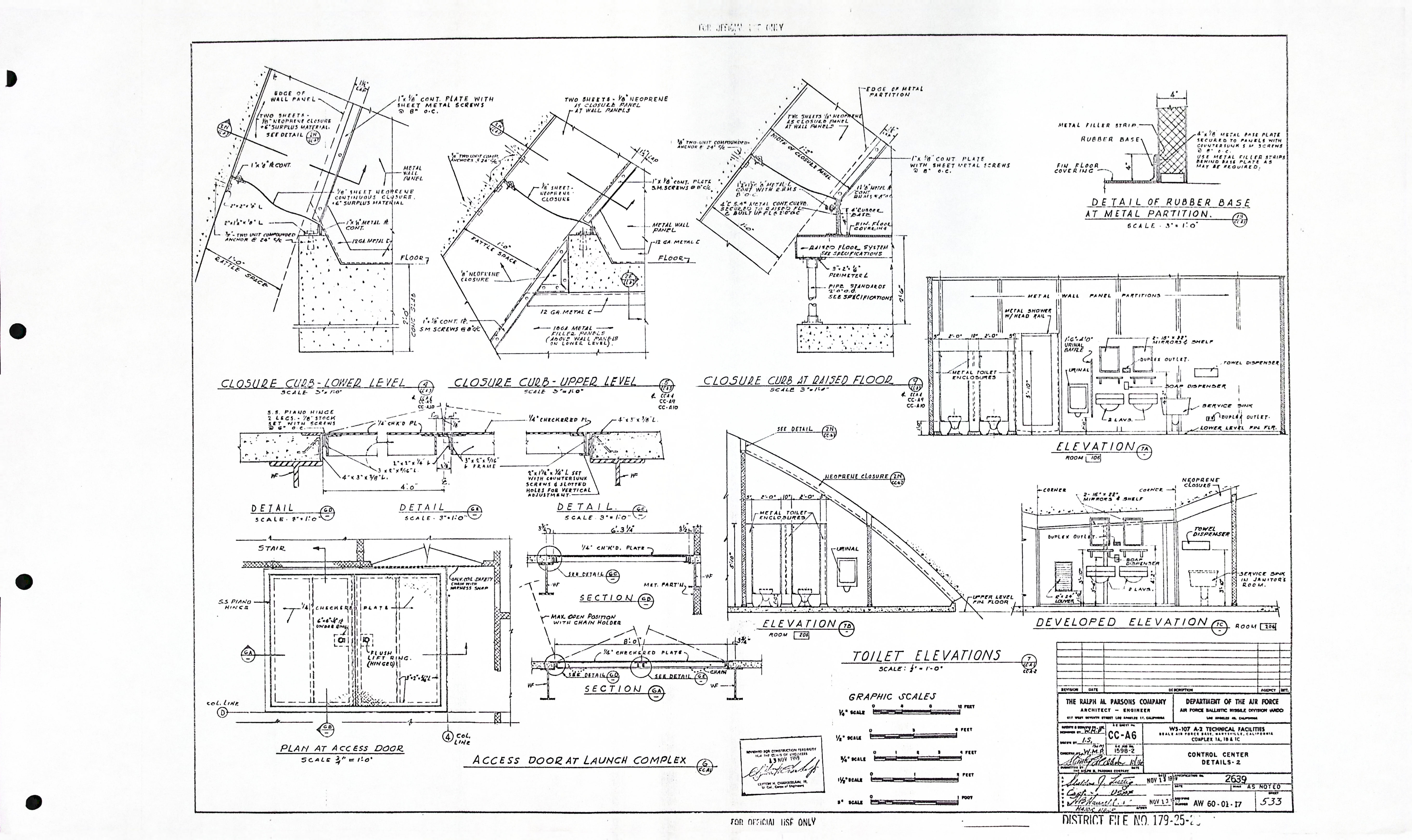
| CC-A6 | DETAILS - 2 |
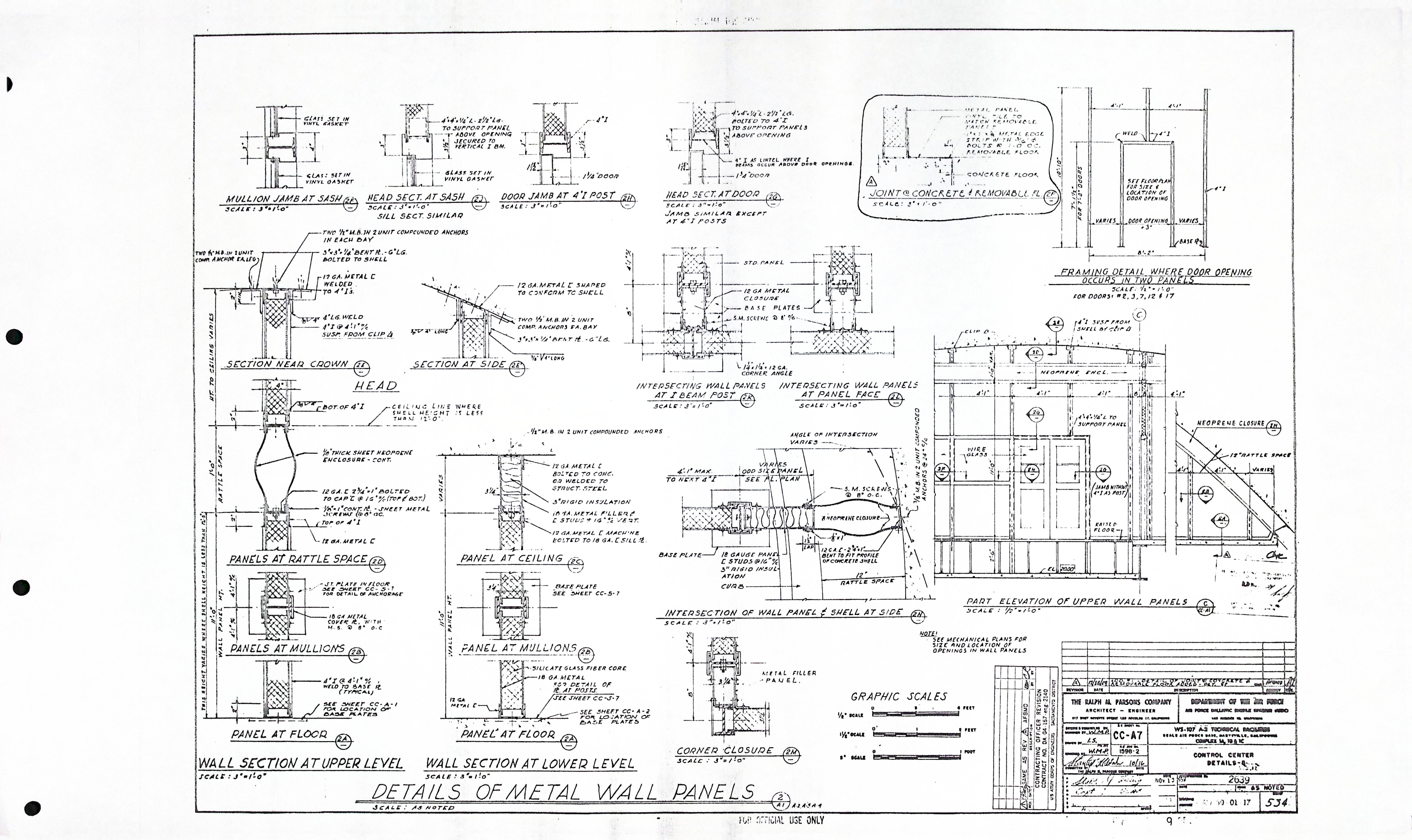
| CC-A7 | DETAILS - 3 |
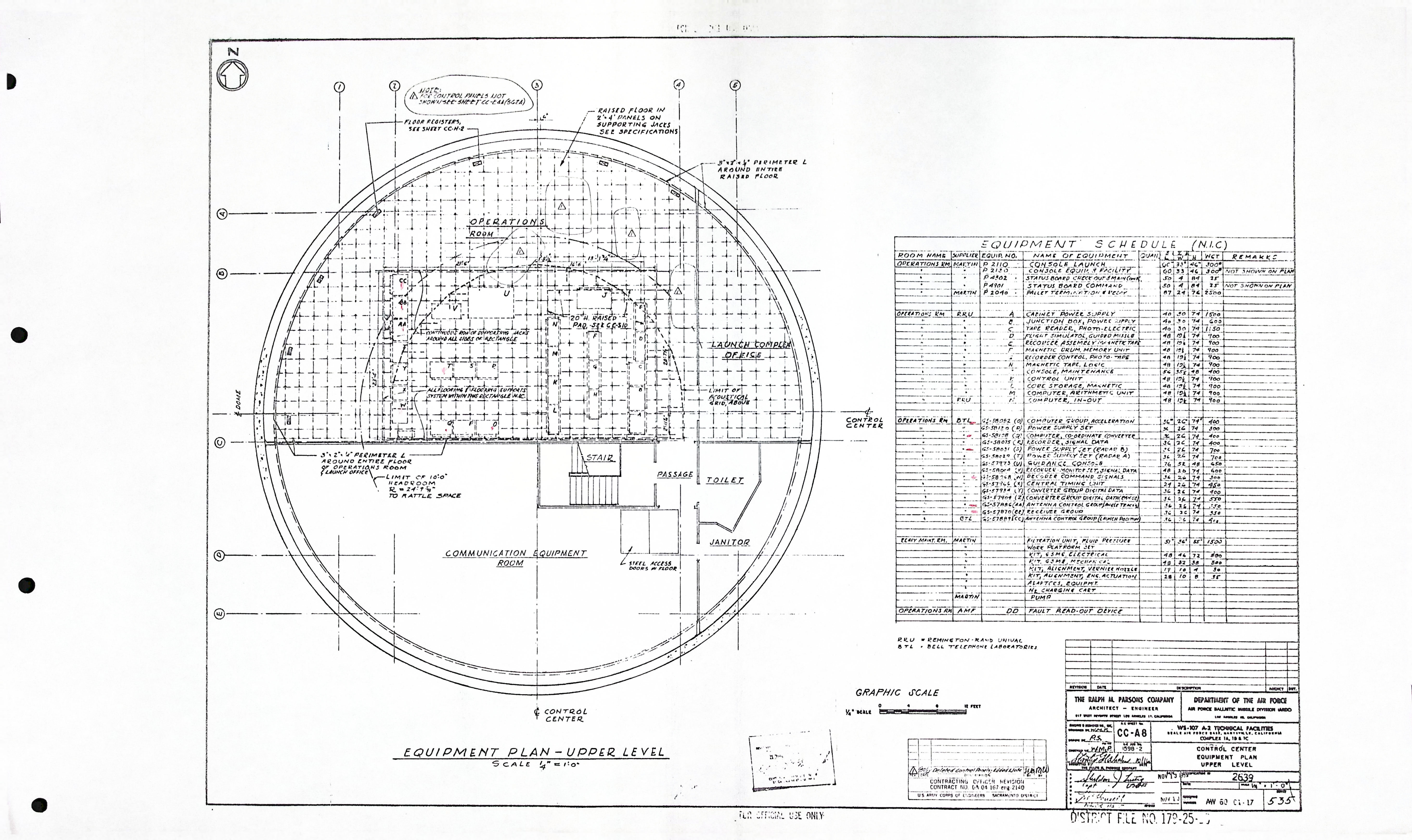
| CC-A8 | EQUIPMENT PLAN UPPER LEVEL |
| CC-A9 | CROSS SECTION - 1 |
| CC-A10 | CROSS SECTION - 2 |
Control Center - Composite drawings (0)
| Drawing Number | Description |
|---|---|
| -- | N/A |
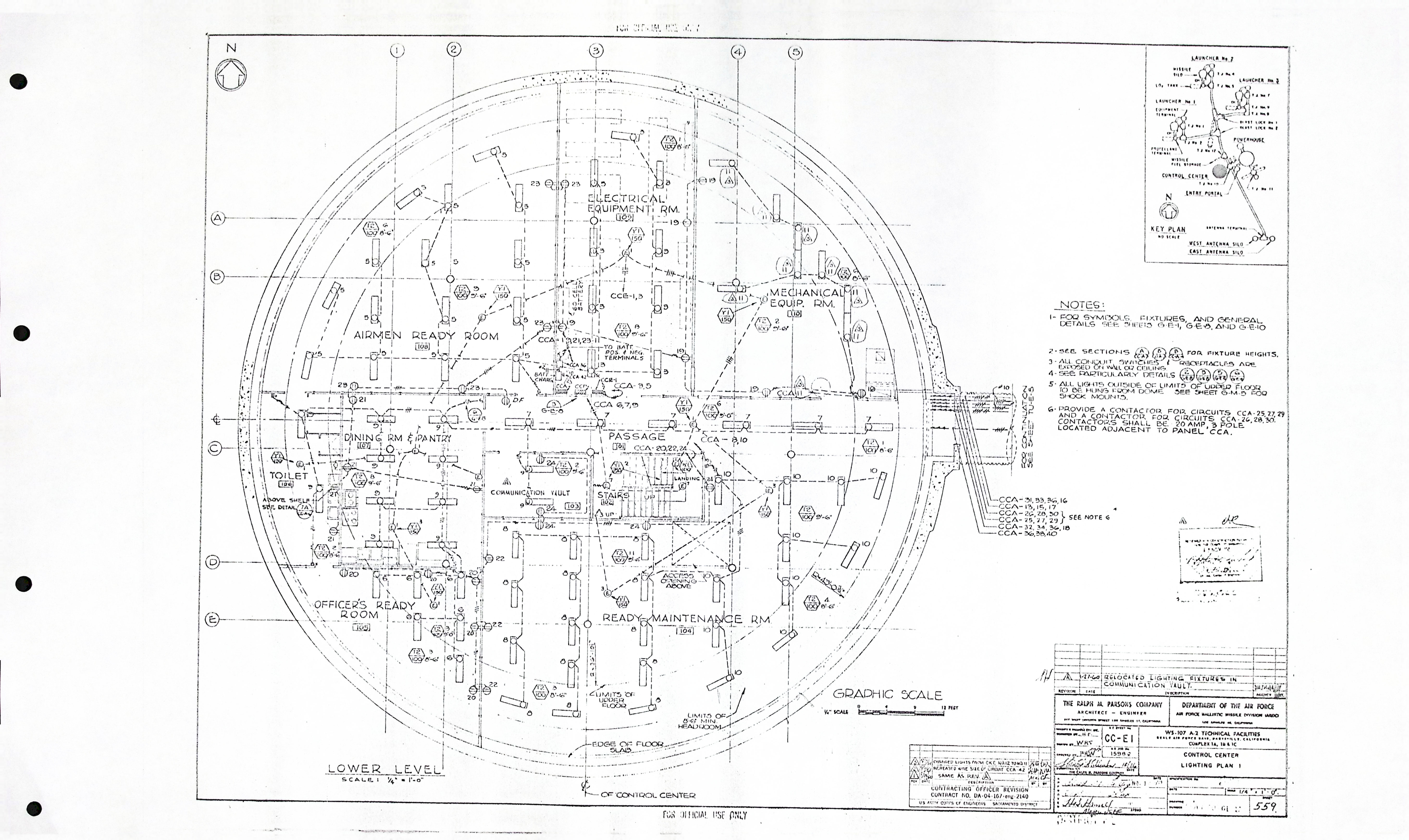
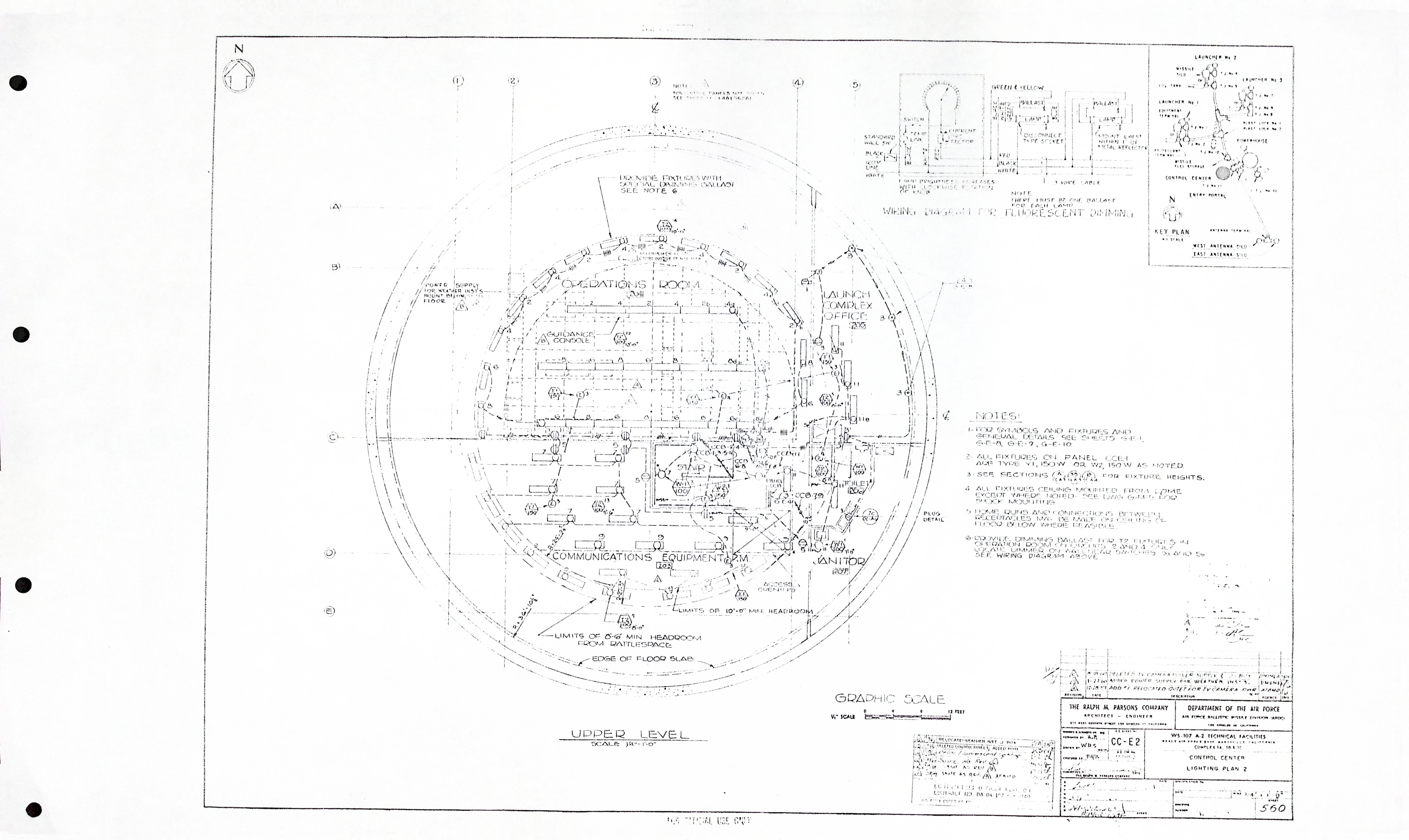
Control Center - Electrical drawings (12)
| Drawing Number | Description |
|---|---|
| CC-E1 | LIGHTING PLAN 1 |
| CC-E2 | LIGHTING PLAN 2 |
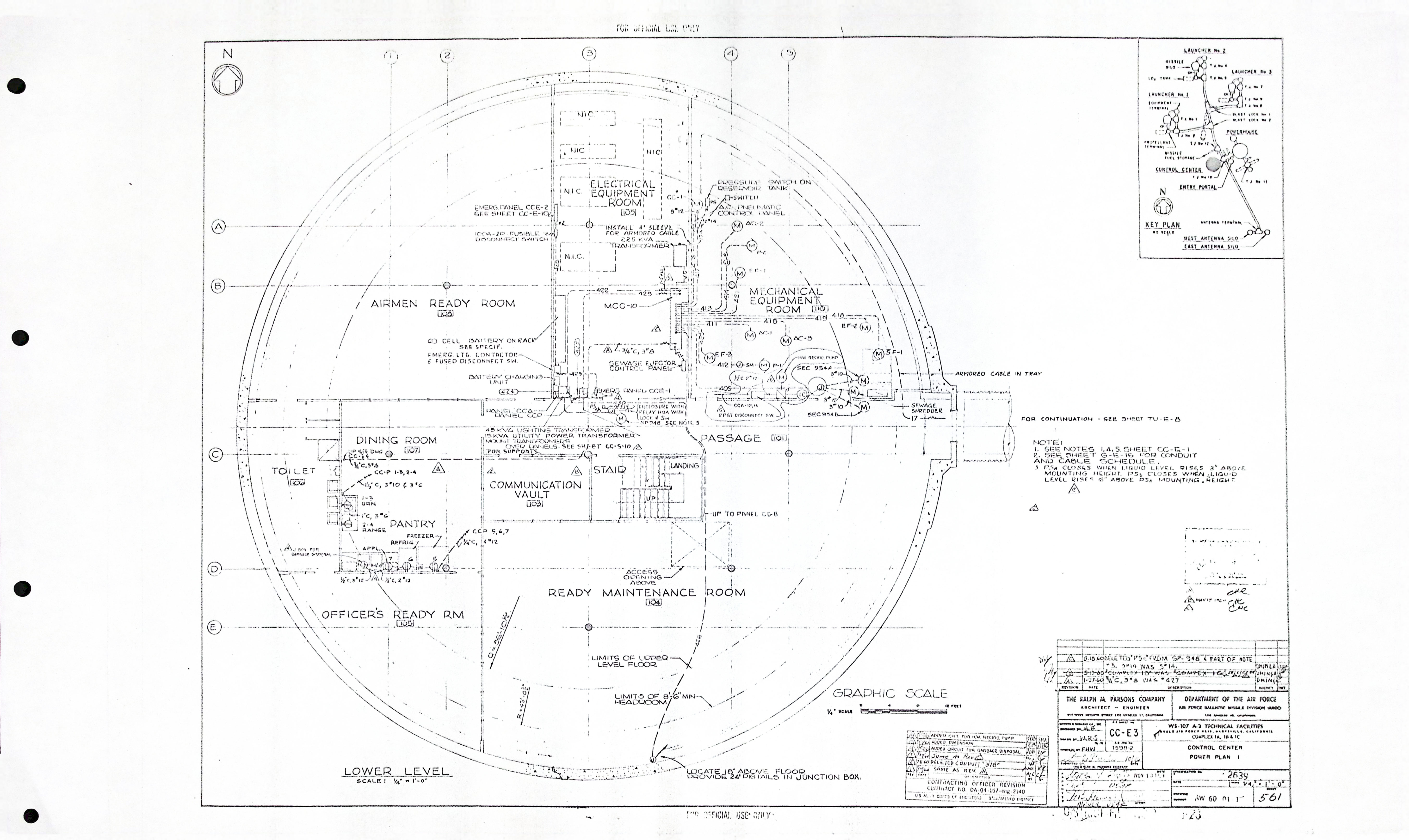
| CC-E3 | POWER PLAN 1 |
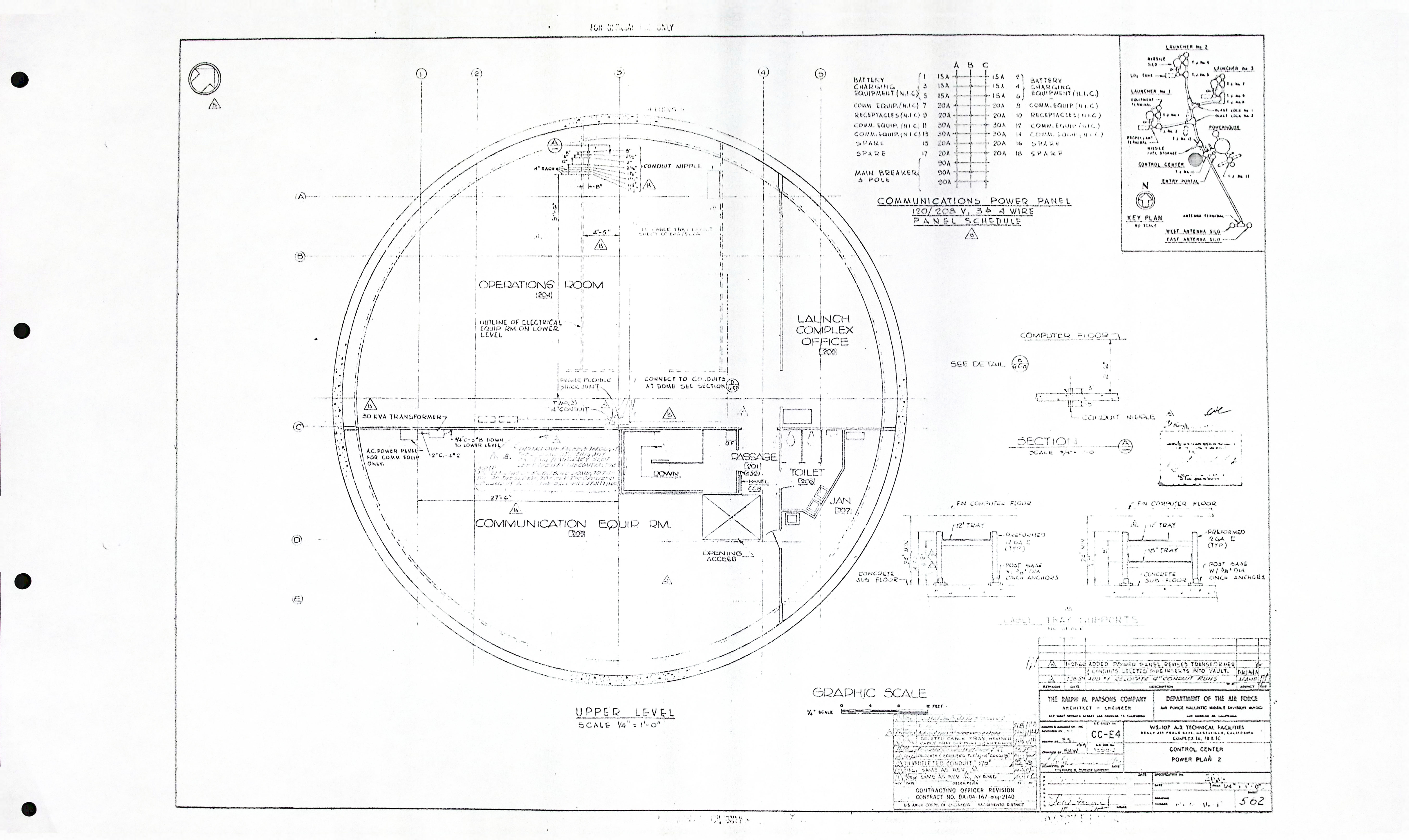
| CC-E4 | POWER PLAN 2 |
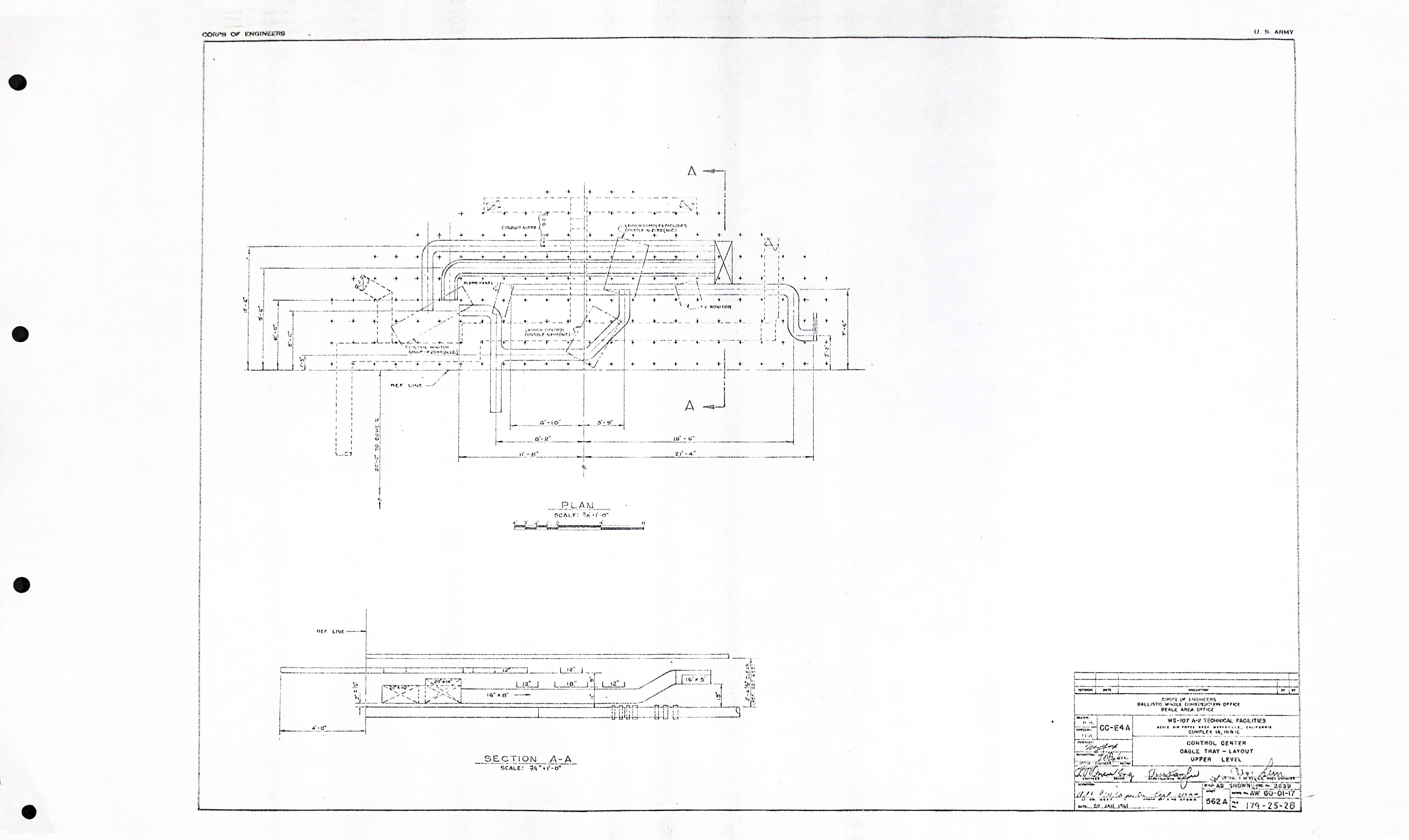
| CC-E4A | CABLE TRAY - LAYOUT UPPER LEVEL |
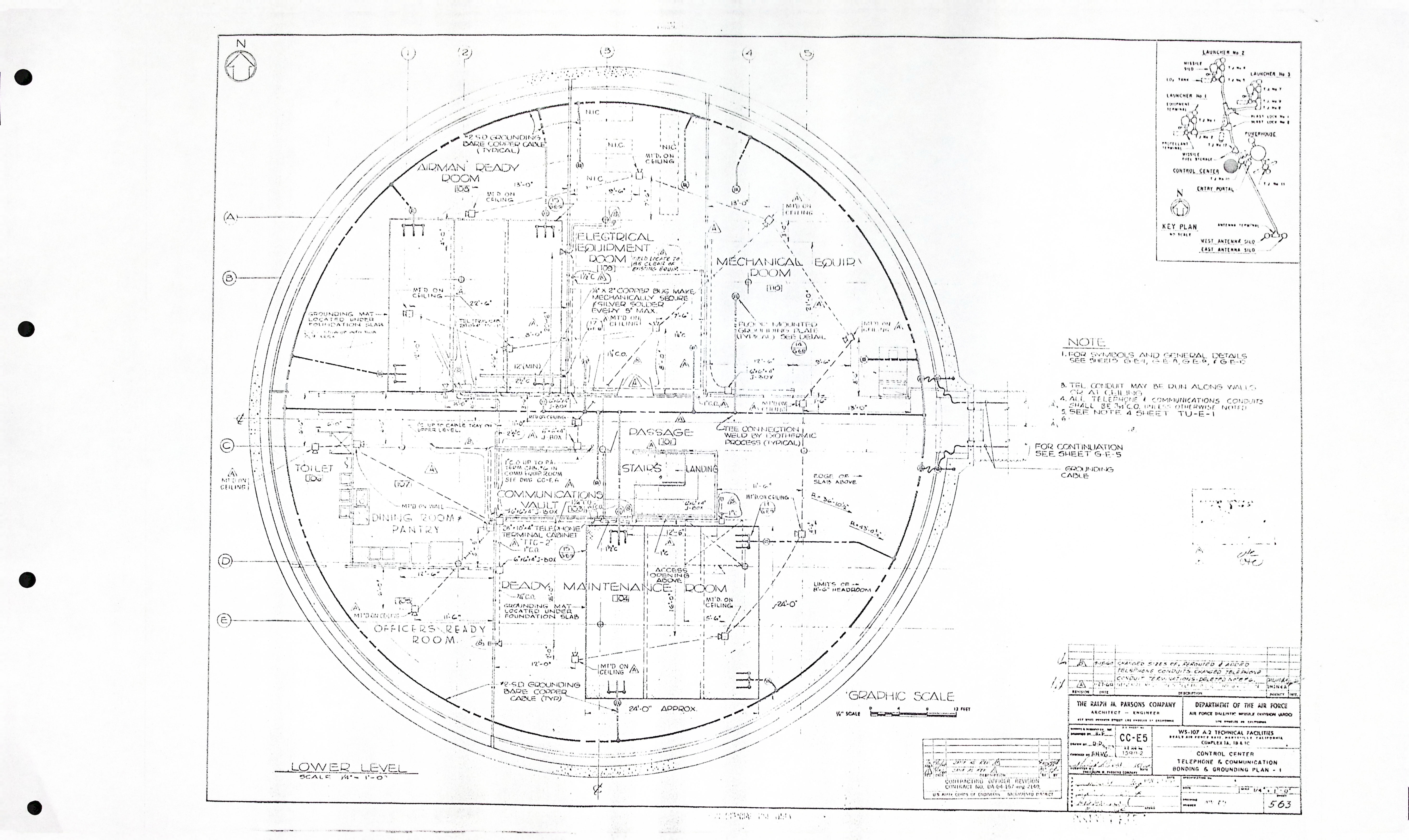
| CC-E5 | TELEPHONE & COMMUNICATION BONDING & GROUNDING PLAN - 1 |
| CC-E6 | TELEPHONE & COMMUNICATION BONDING & GROUNDING PLAN - 2 |
| CC-E7 | 480 VOLT SINGLE LINE DIAGRAM SCHEMATIC DIAGRAMS & DETAILS |
| CC-E8 | CABLE TRAY PLAN |
| CC-E9 | CABLE TRAY DETAILS |
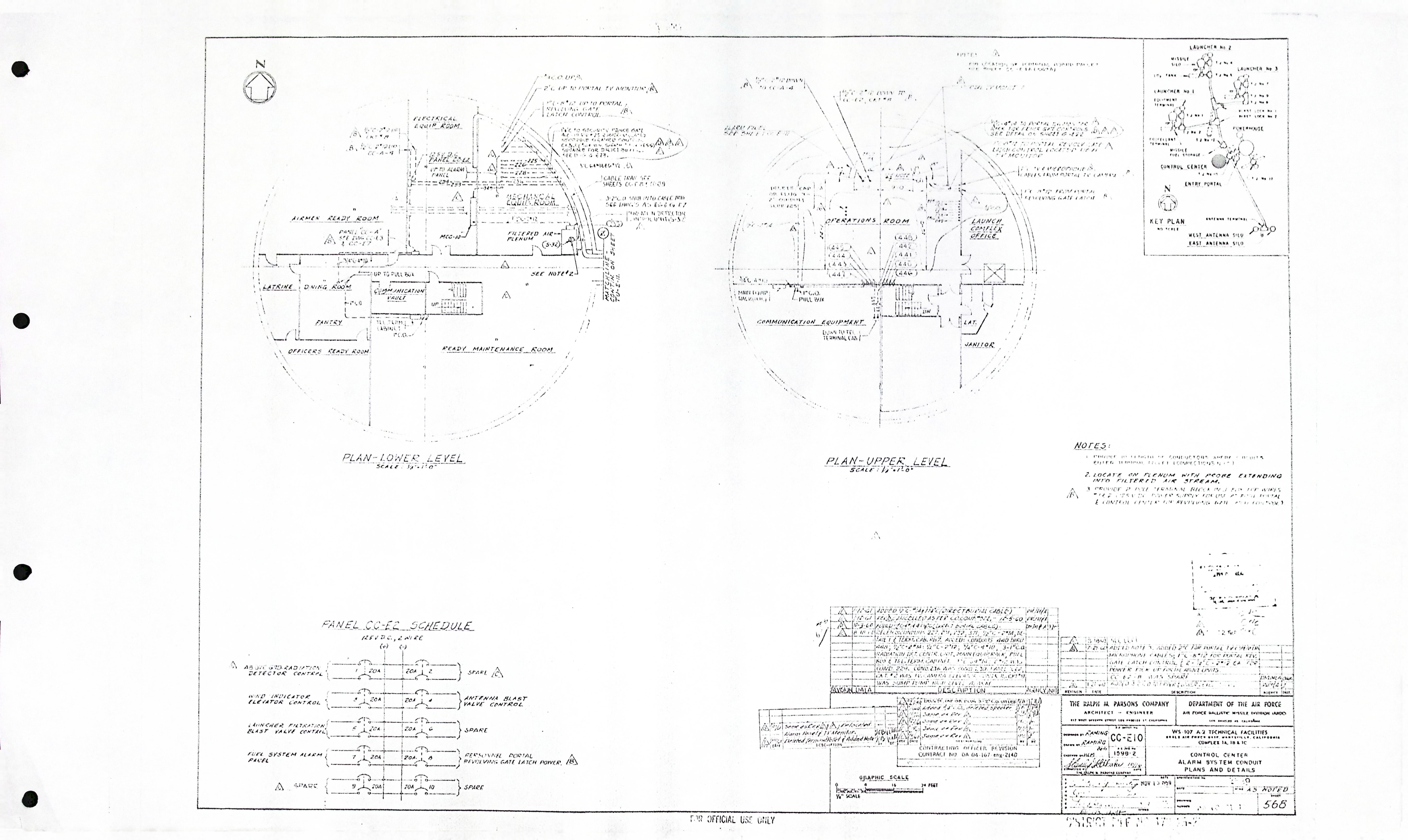
| CC-E10 | ALARM SYSTEM CONDUIT PLANS AND DETAILS |
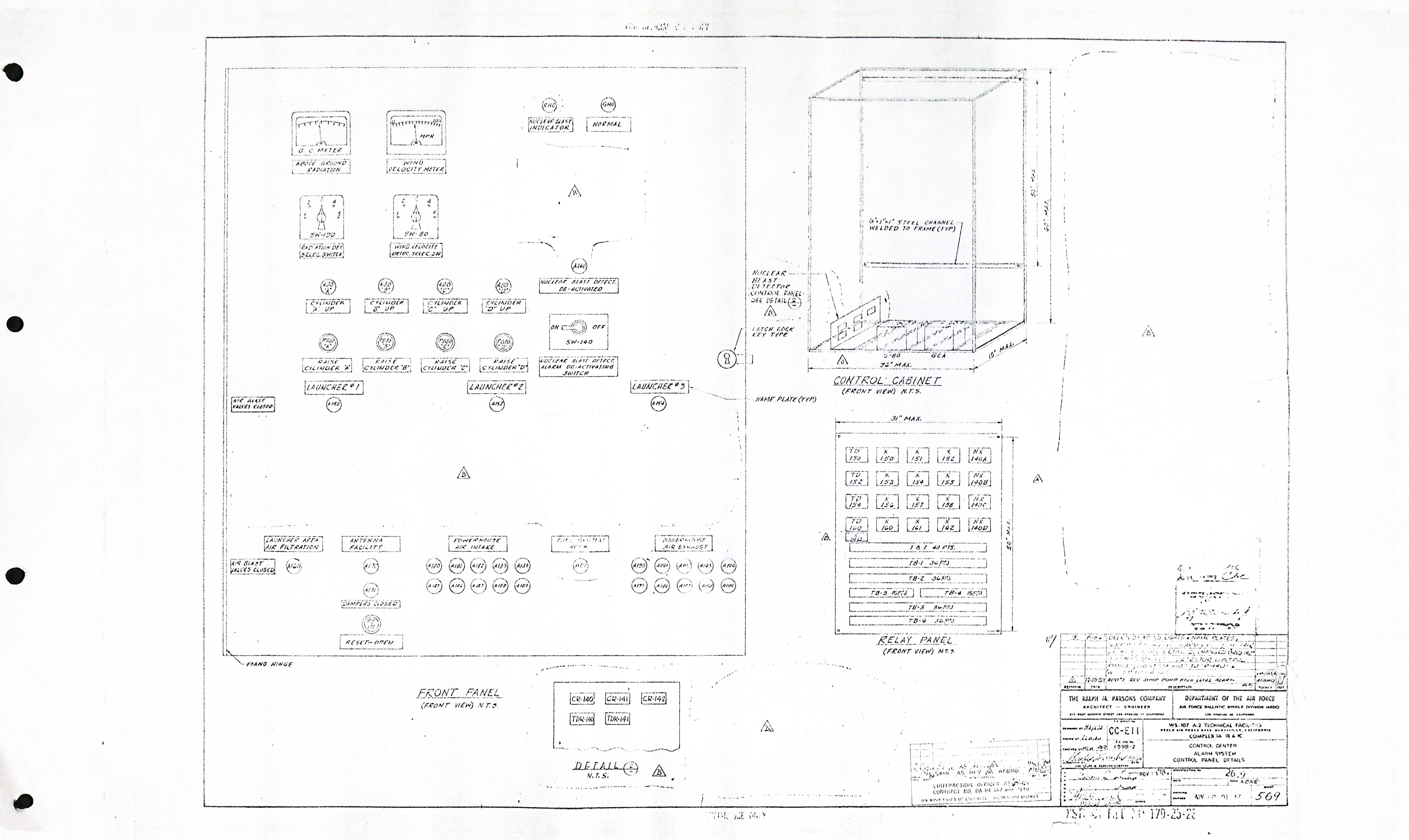
| CC-E11 | ALARM SYSTEM CONTROL PANEL DETAILS |
Control Center - HVAC drawings (7)
| Drawing Number | Description |
|---|---|
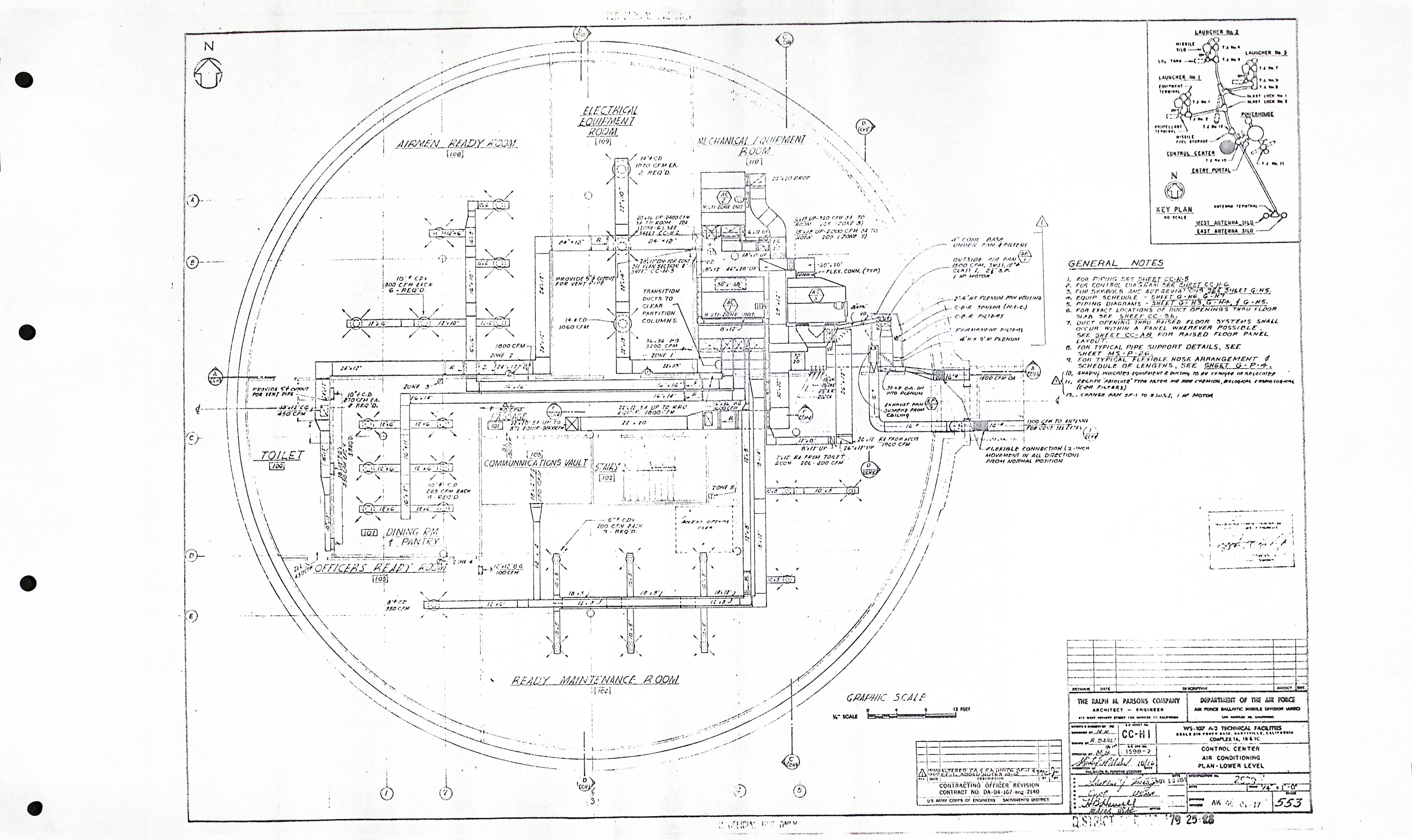
| CC-H1 | AIR CONDITIONING PLAN - LOWER LEVEL |
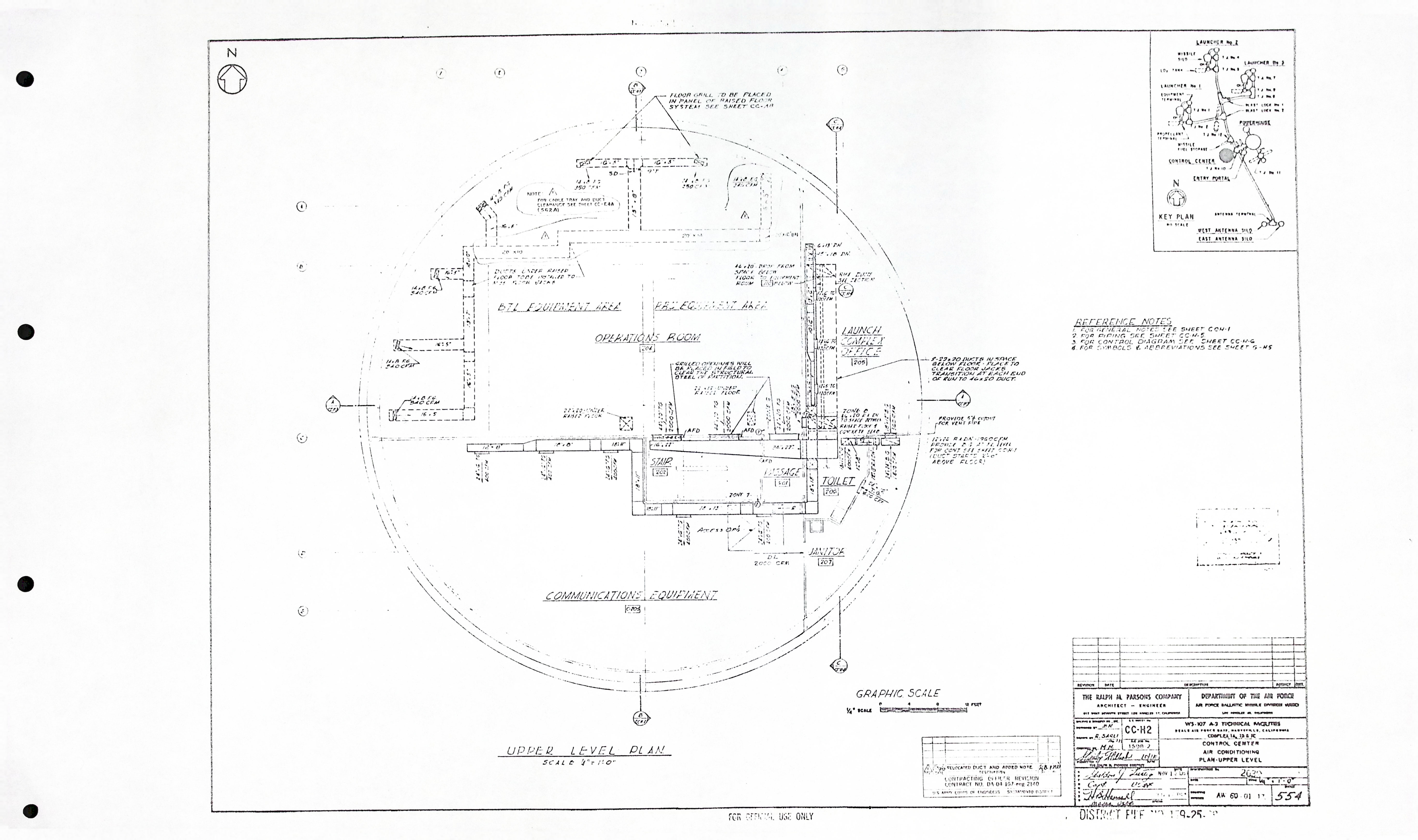
| CC-H2 | AIR CONDITIONING PLAN - UPPER LEVEL |
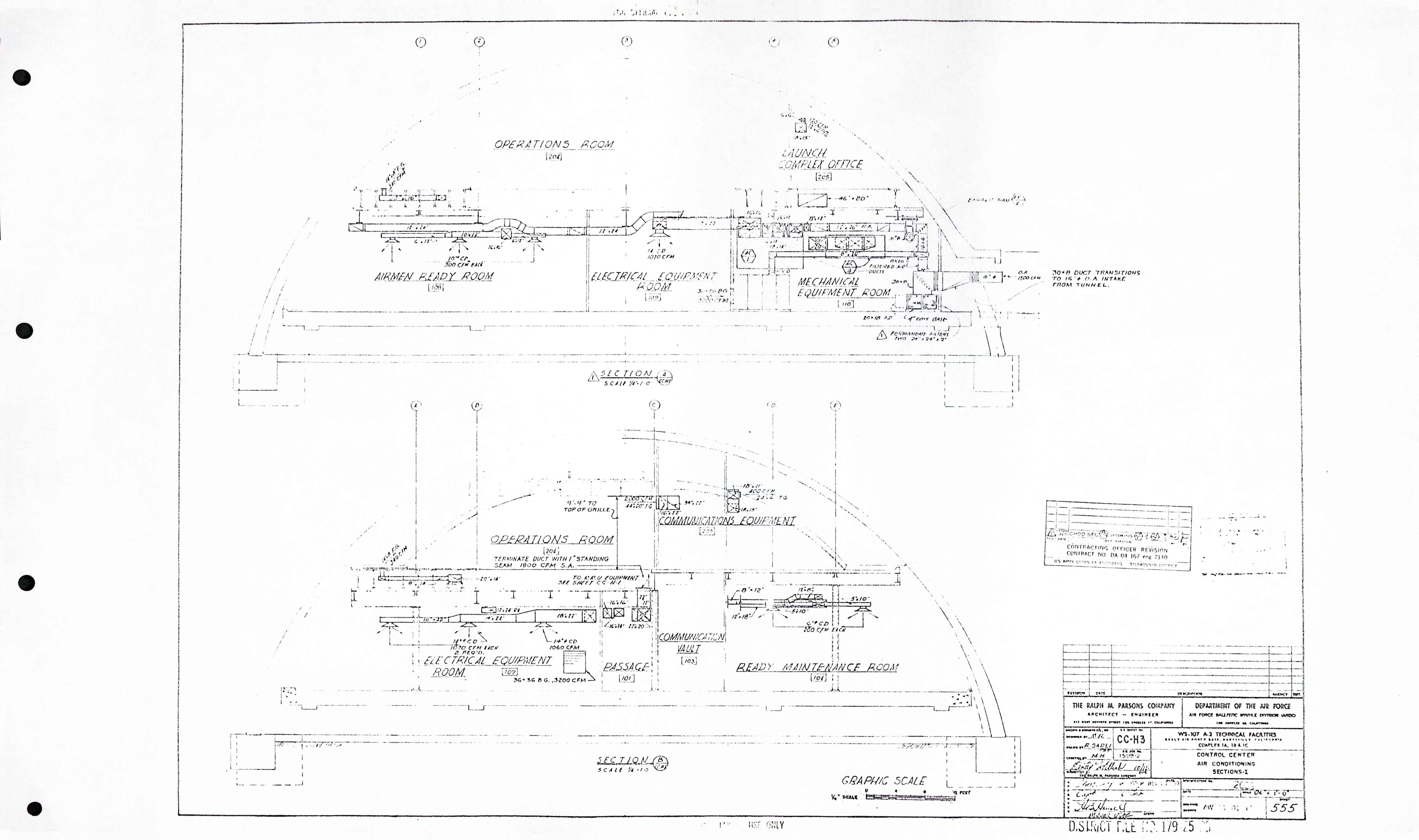
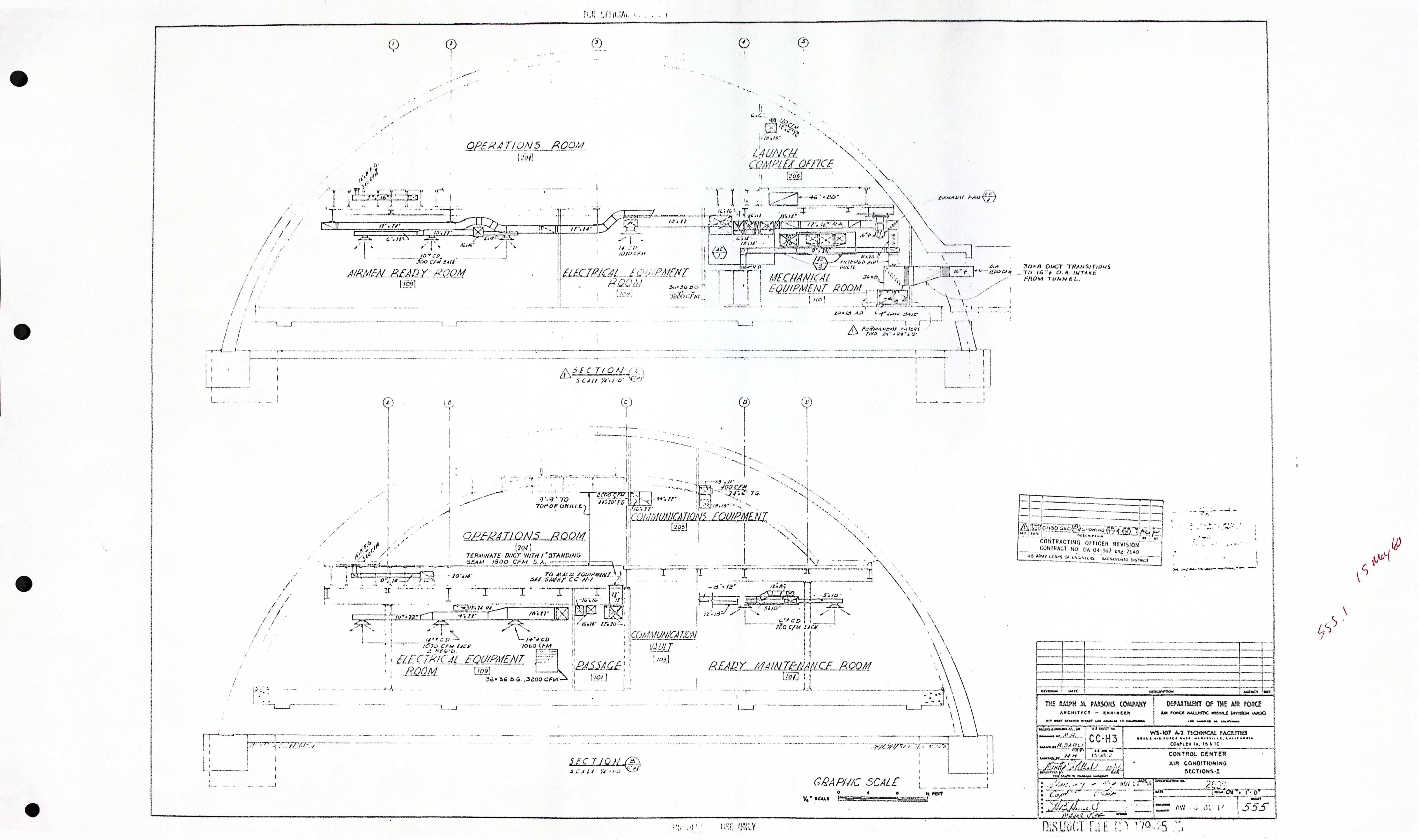
| CC-H3 | AIR CONDITIONING SECTIONS - I |
| CC-H3 | AIR CONDITIONING SECTIONS - I * |
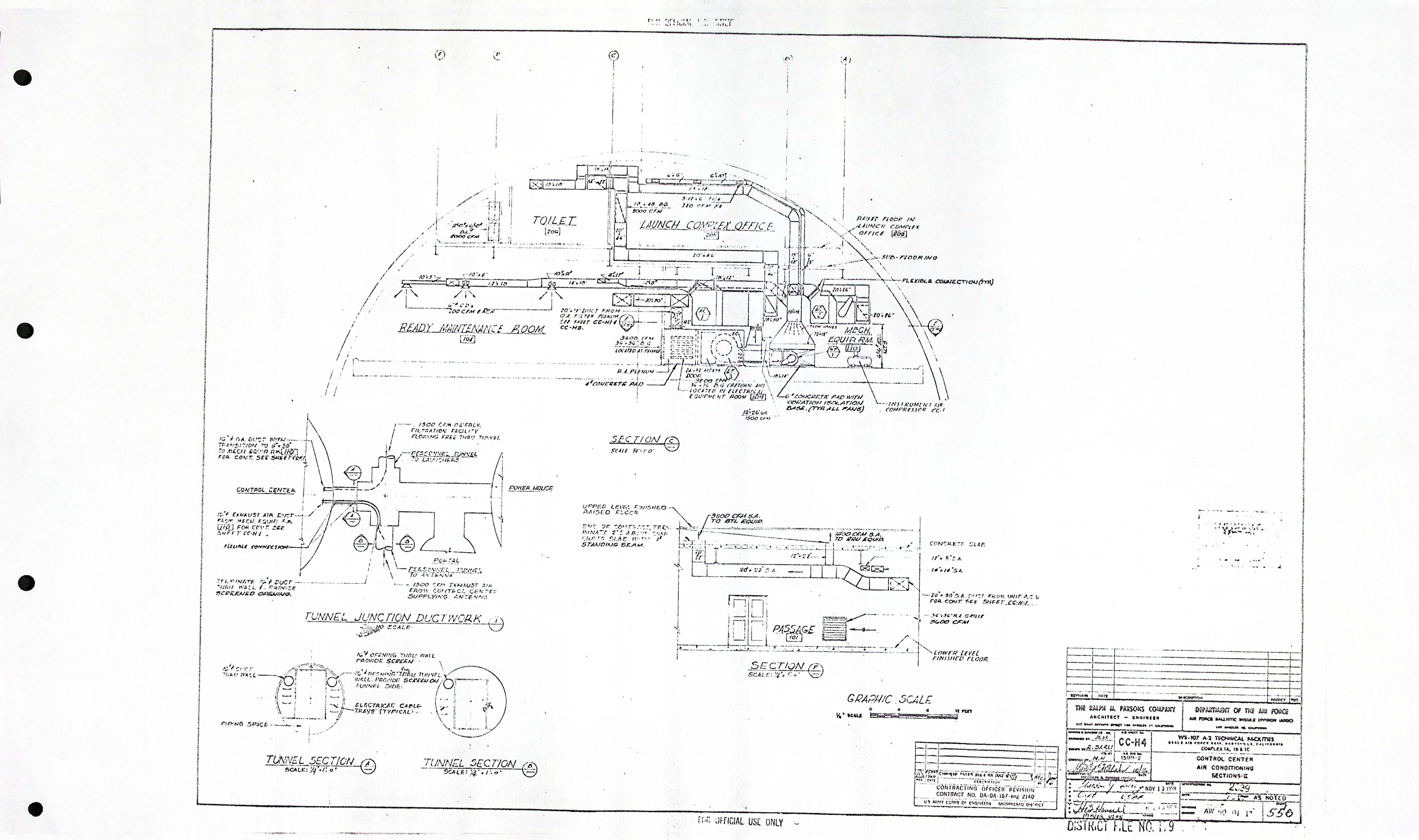
| CC-H4 | AIR CONDITIONING SECTIONS - II |
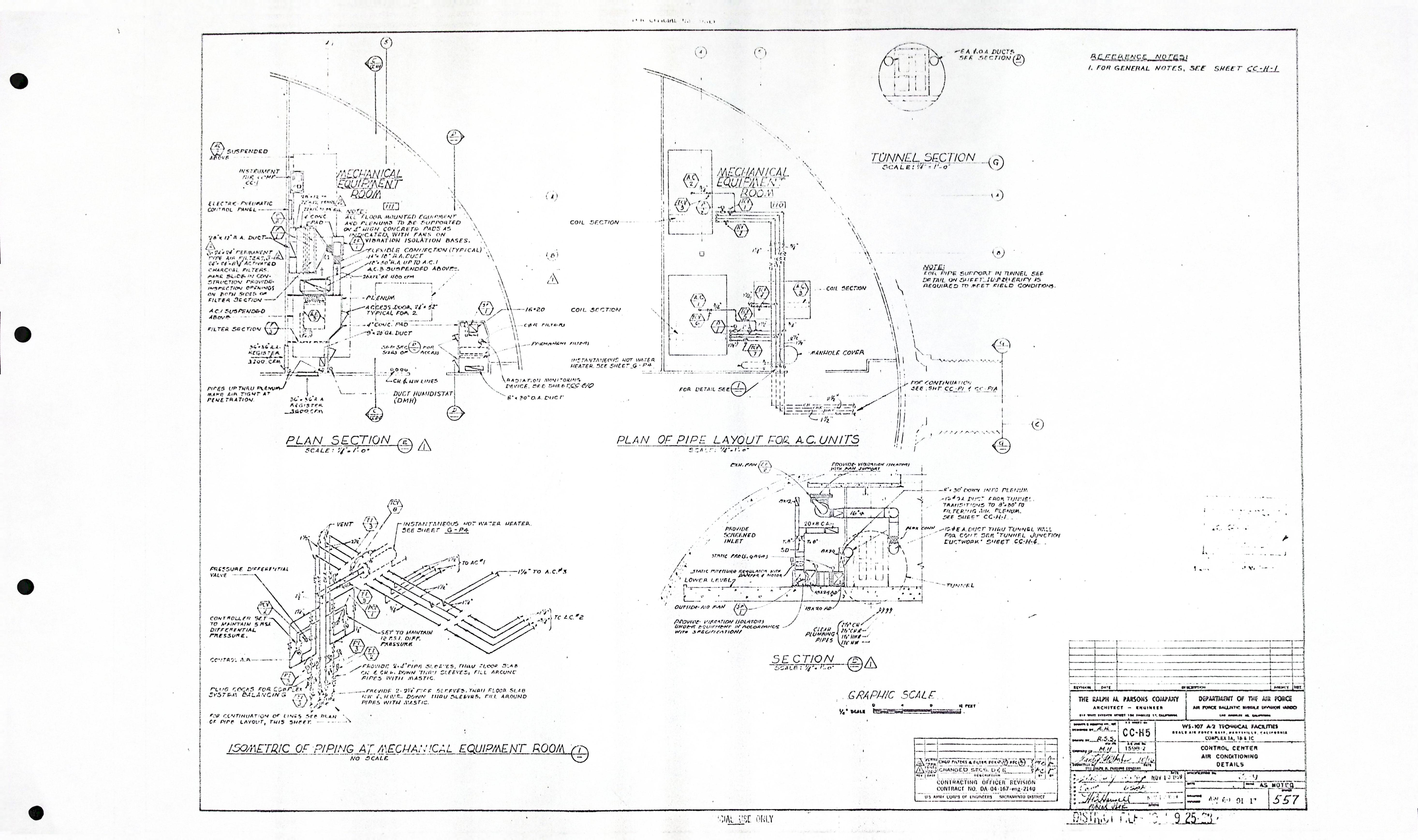
| CC-H5 | AIR CONDITIONING DETAILS |
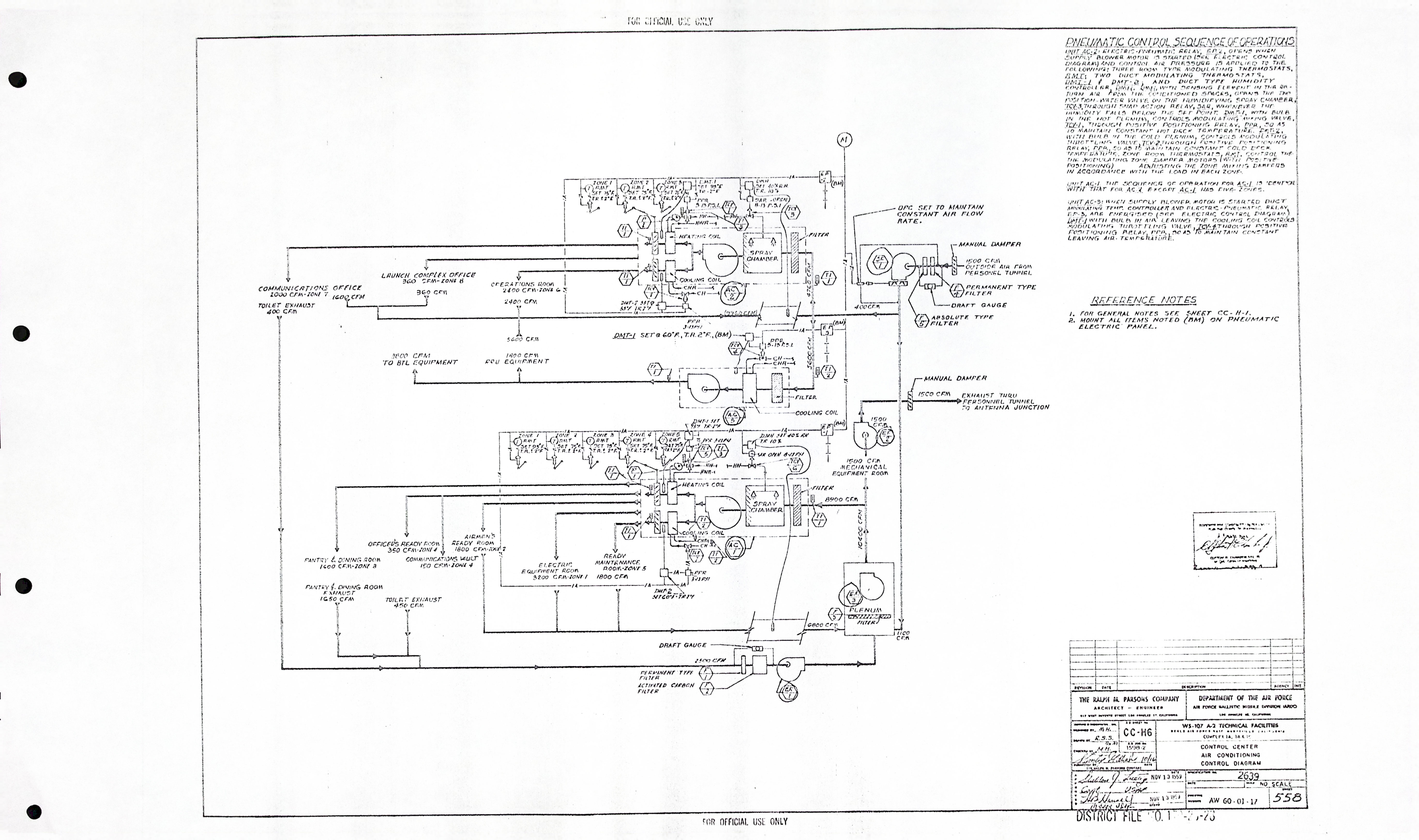
| CC-H6 | AIR CONDITIONING CONTROL DIAGRAM |
Control Center - Mechanical drawings (0)
| Drawing Number | Description |
|---|---|
| -- | N/A |
Control Center - Plumbing/Piping drawings (3)
| Drawing Number | Description |
|---|---|
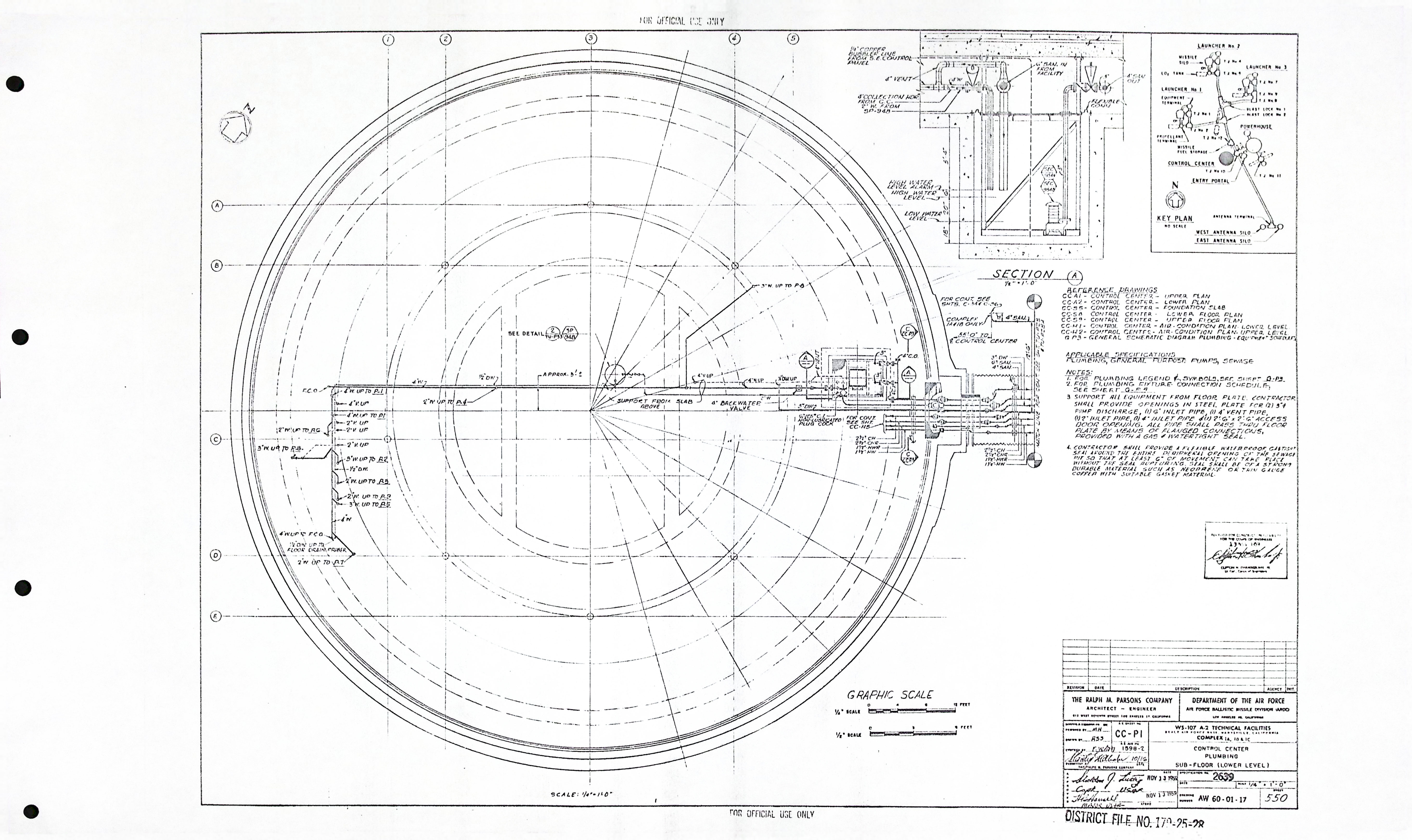
| CC-P1 | PLUMBING PLUMBING SUB-FLOOR (LOWER LEVEL) |
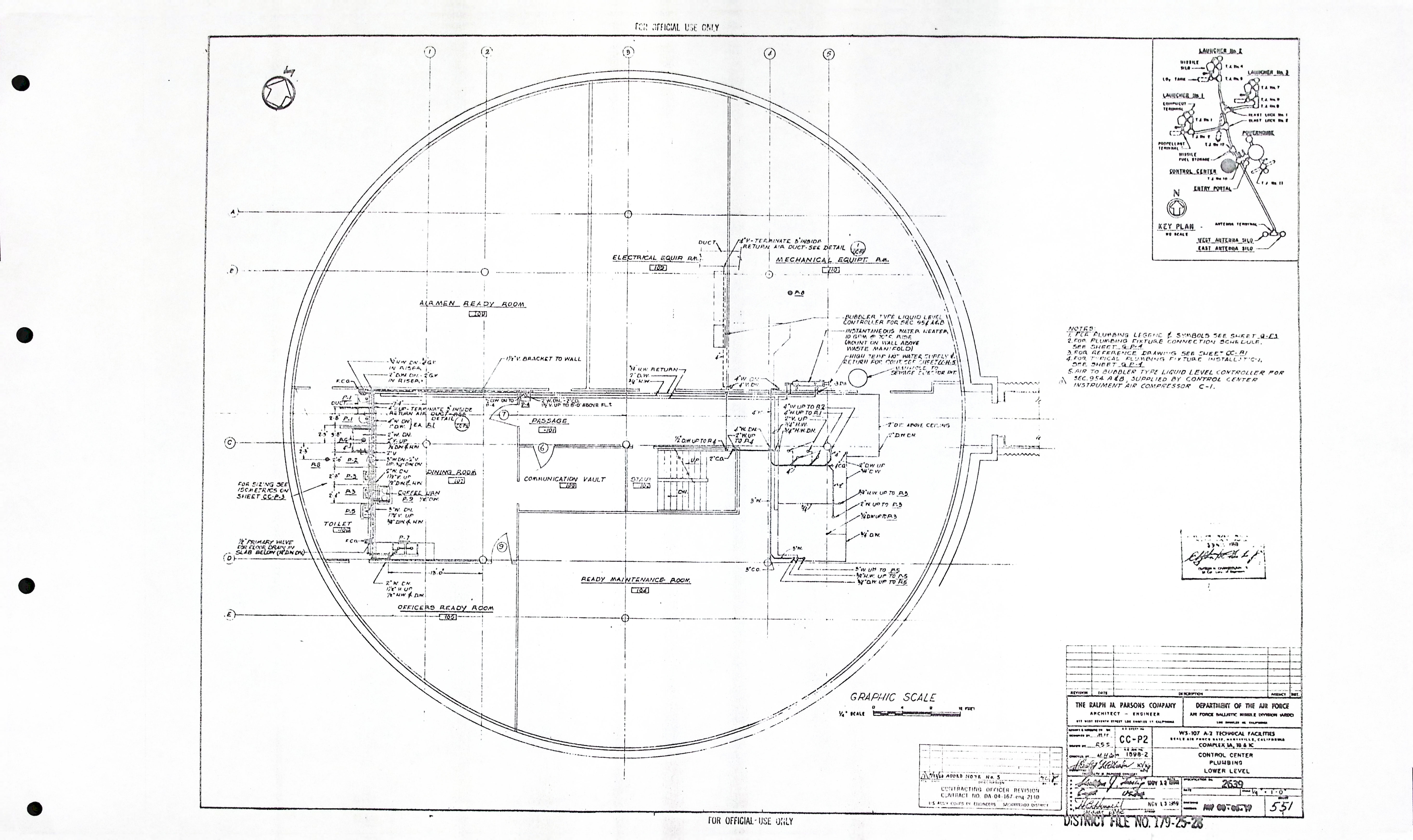
| CC-P2 | PLUMBING LOWER LEVEL |
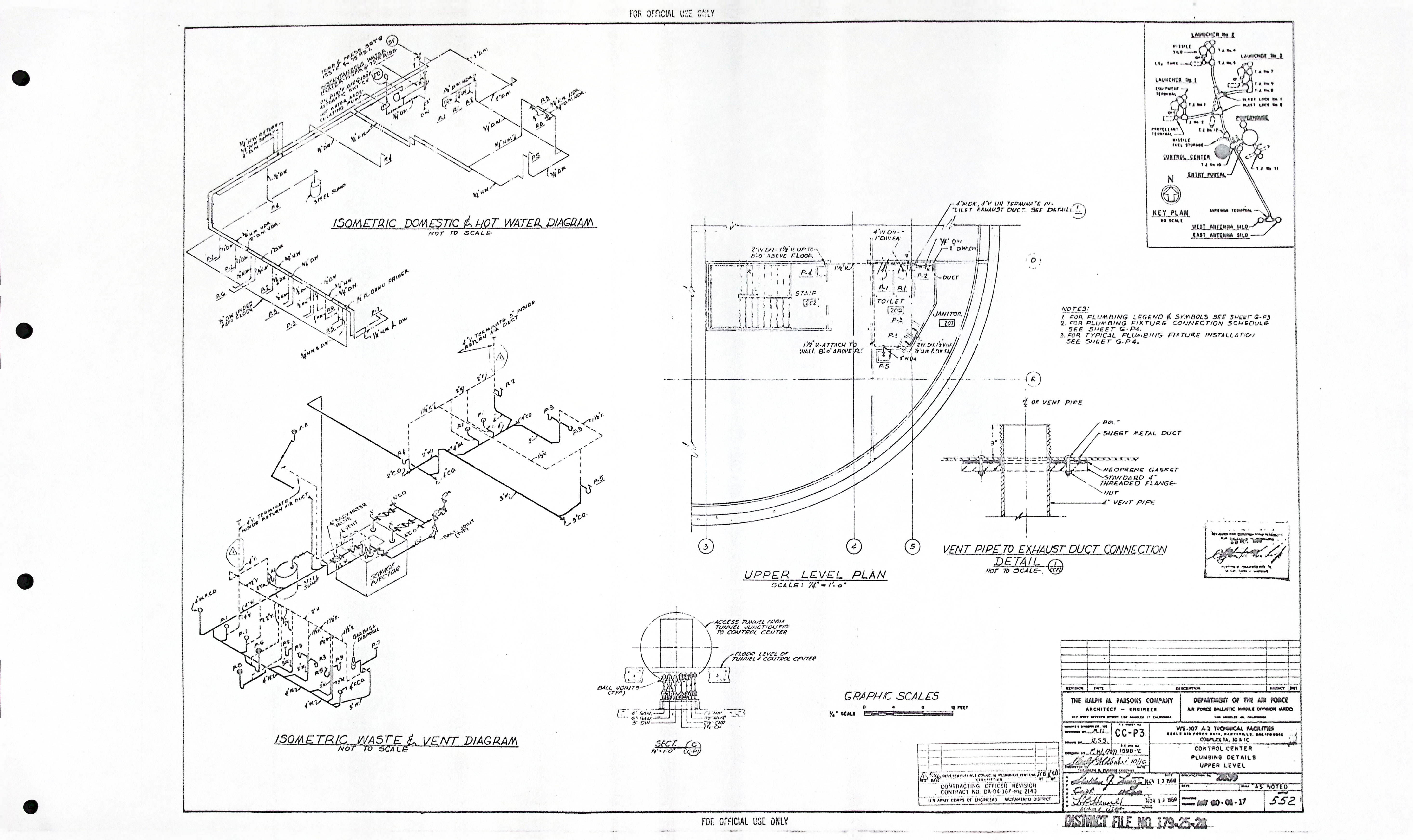
| CC-P3 | PLUMBING DETAILS UPPER LEVEL |
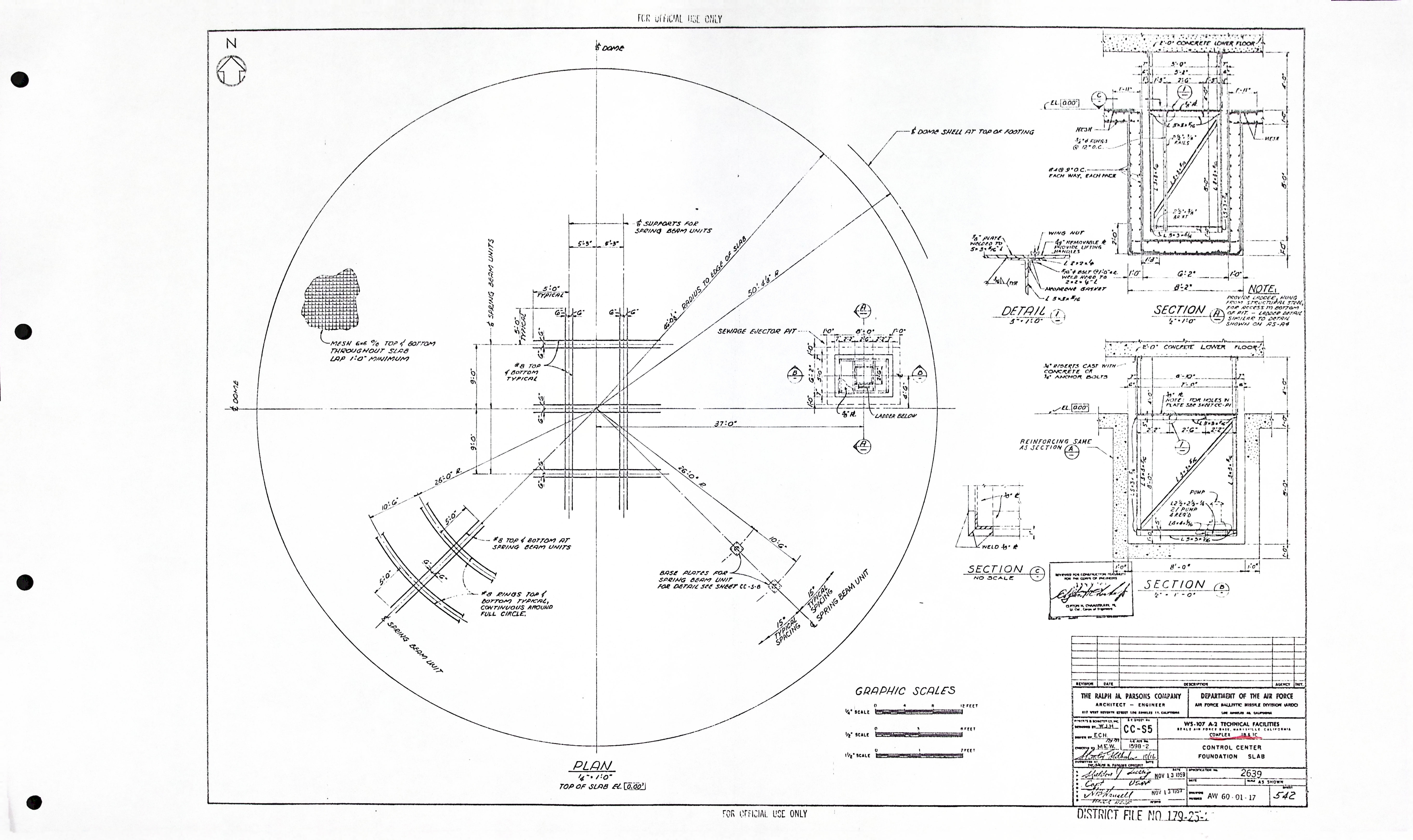
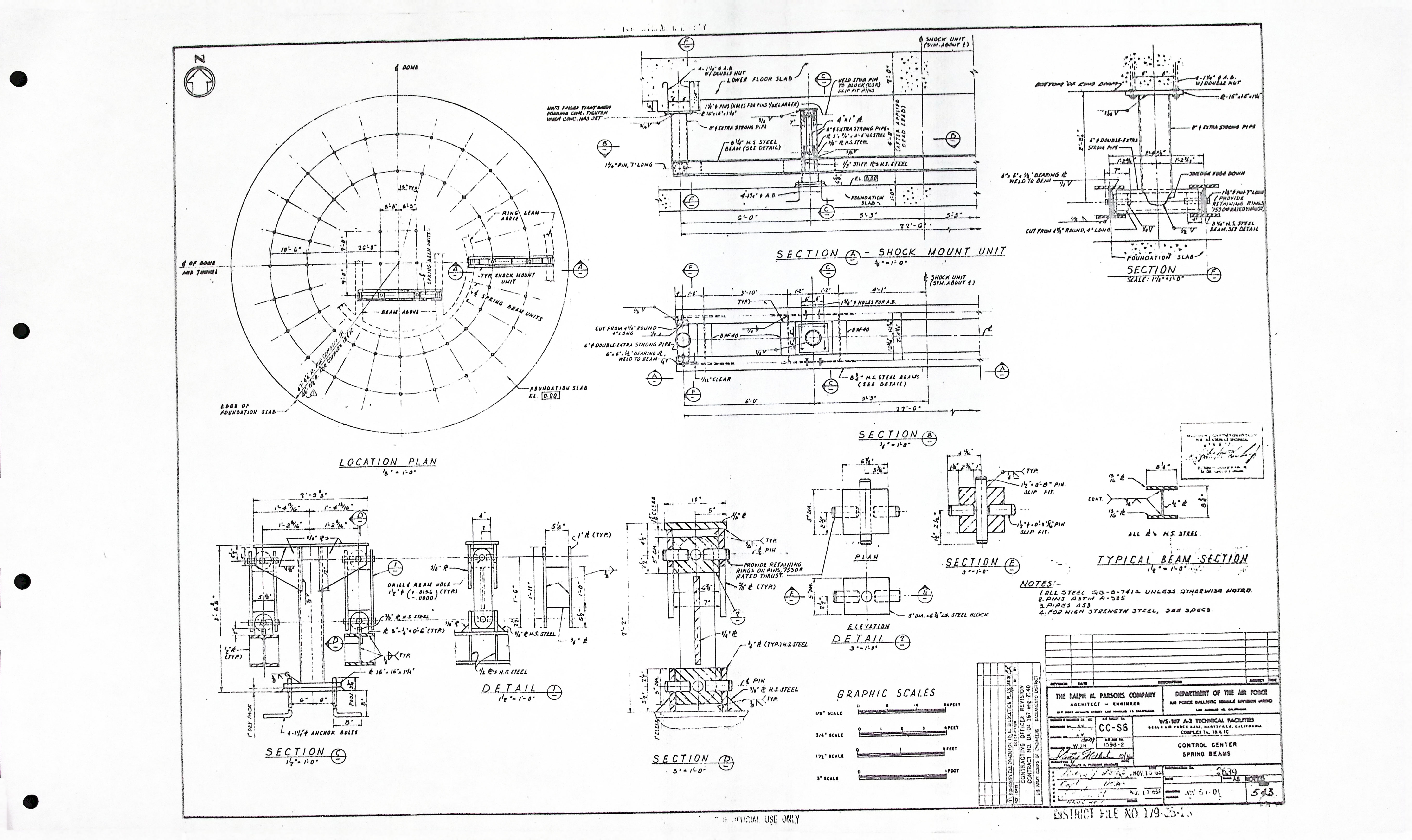
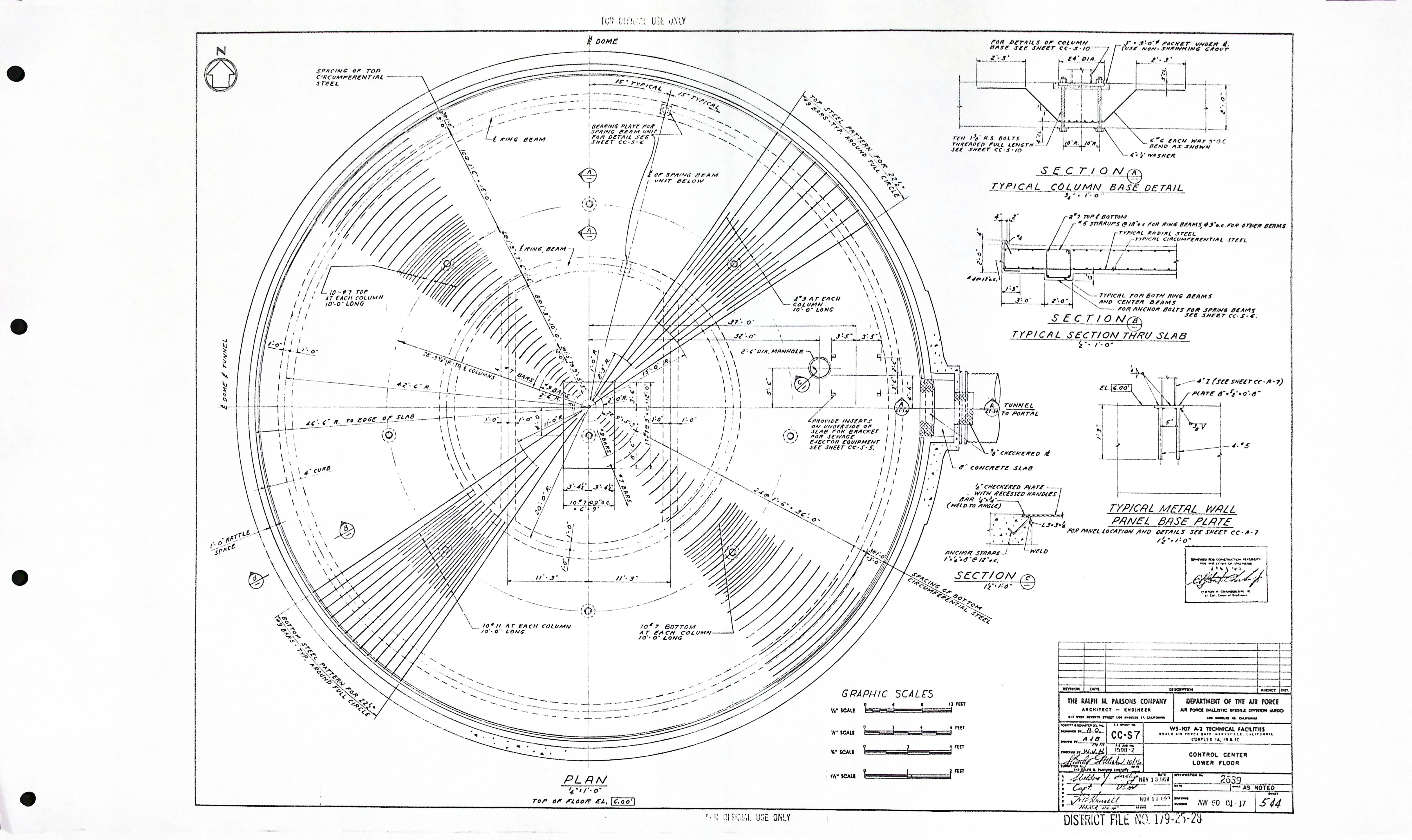
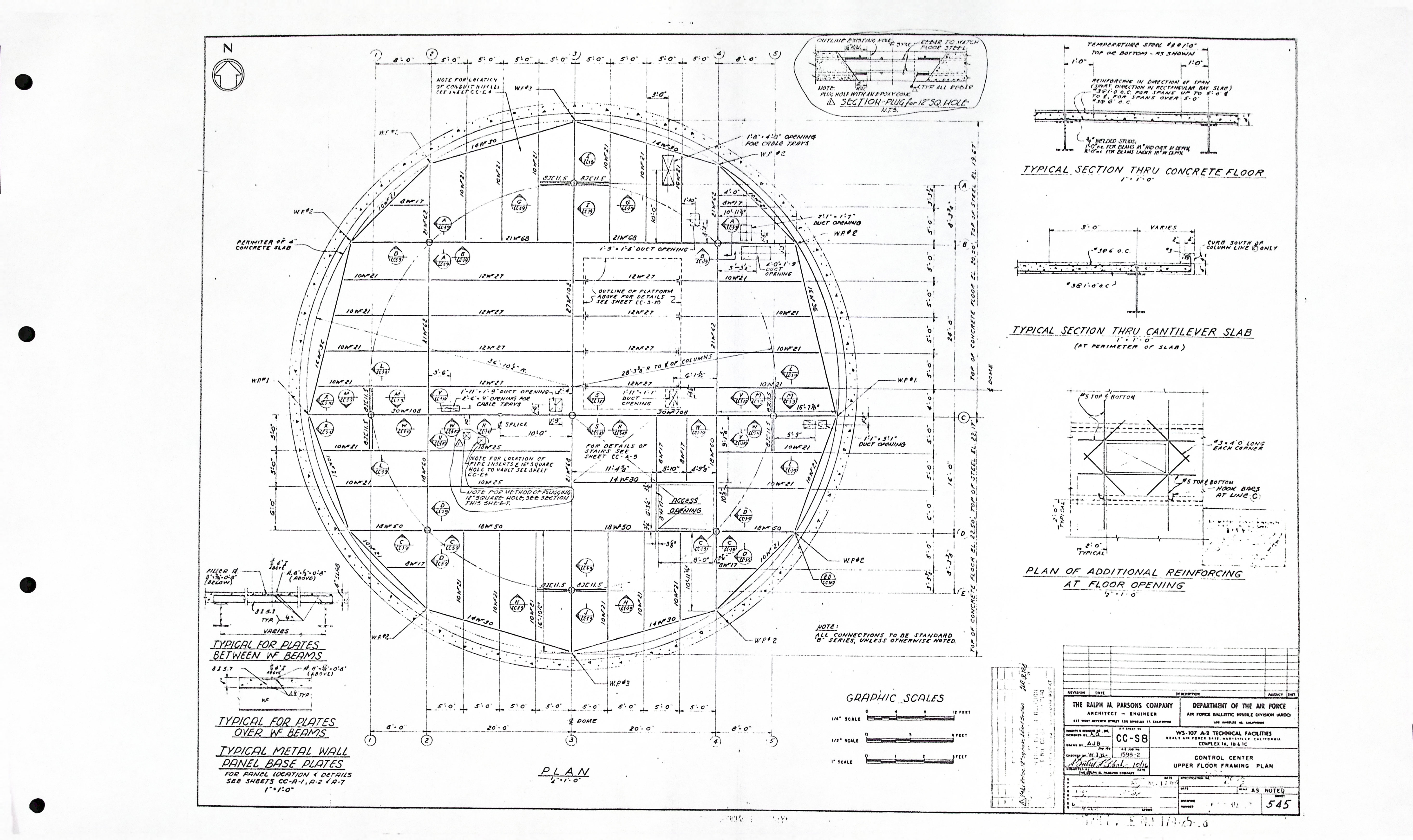
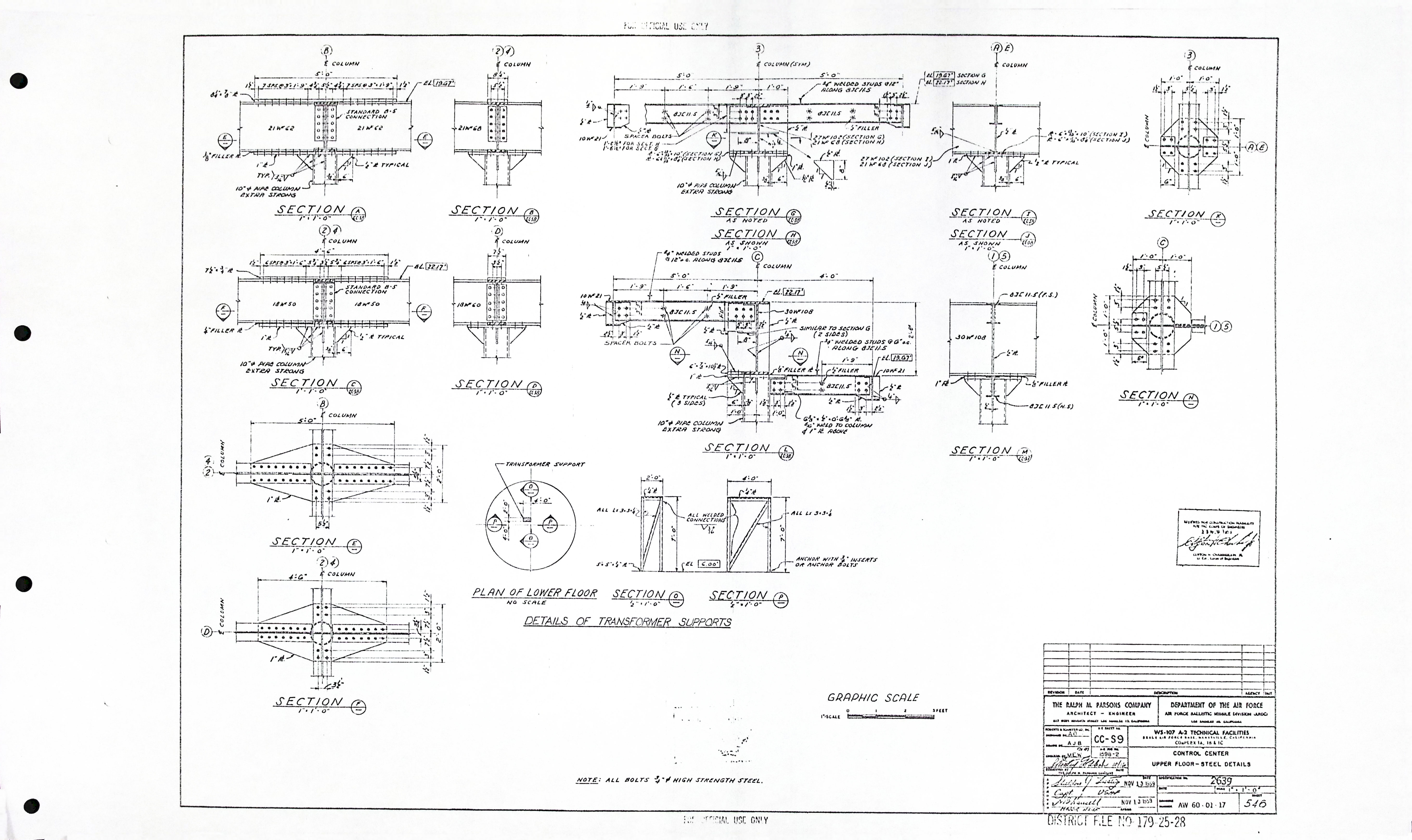
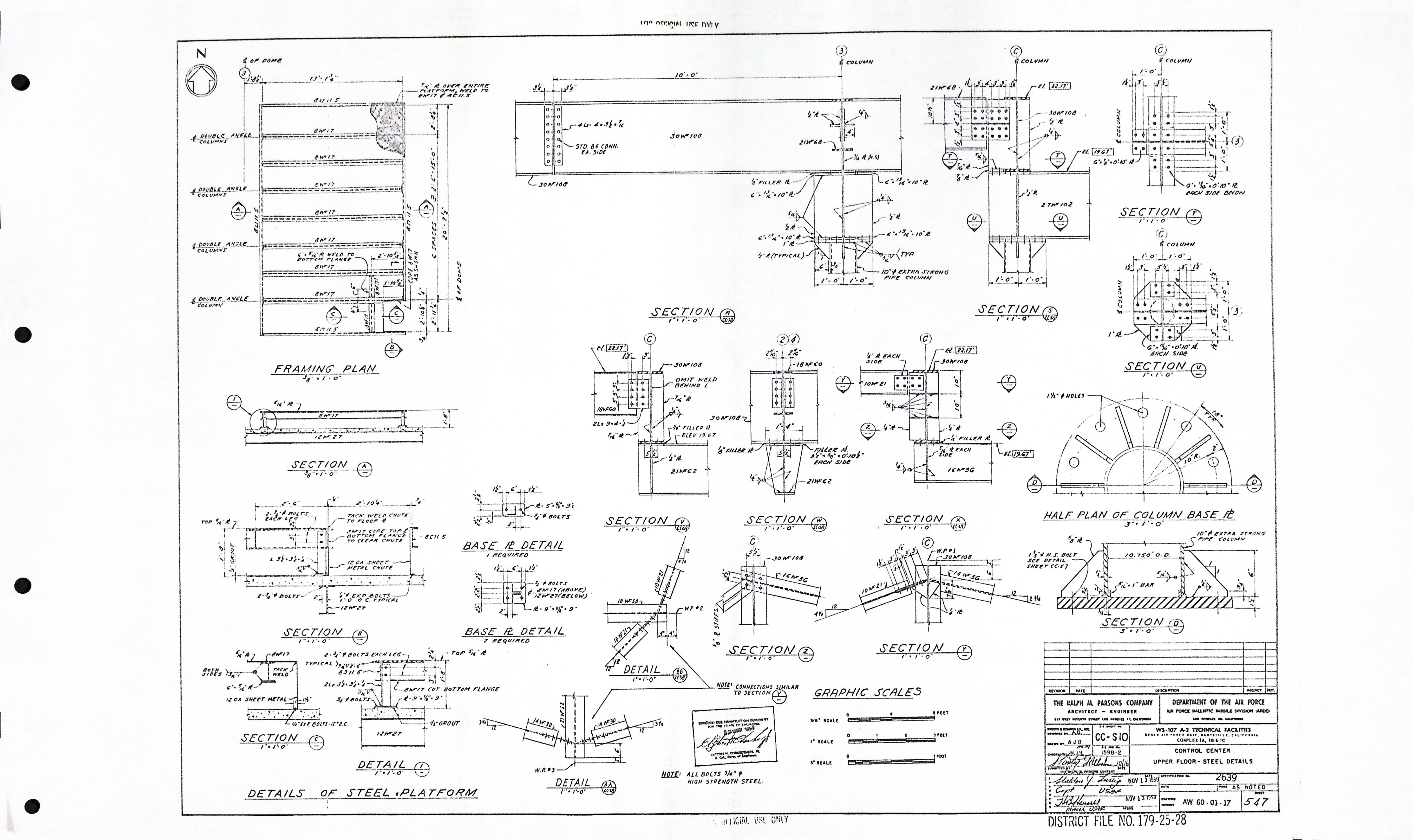
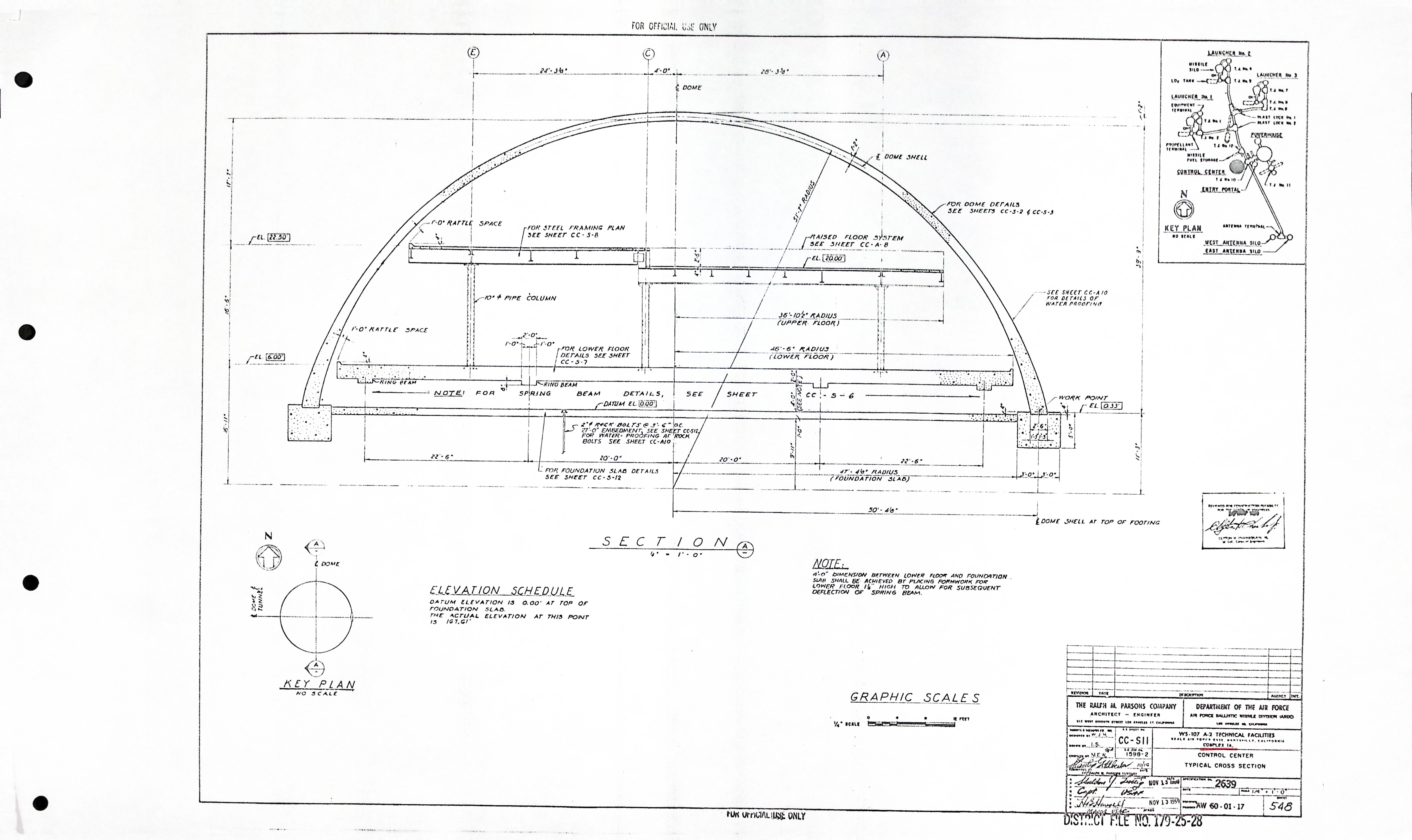
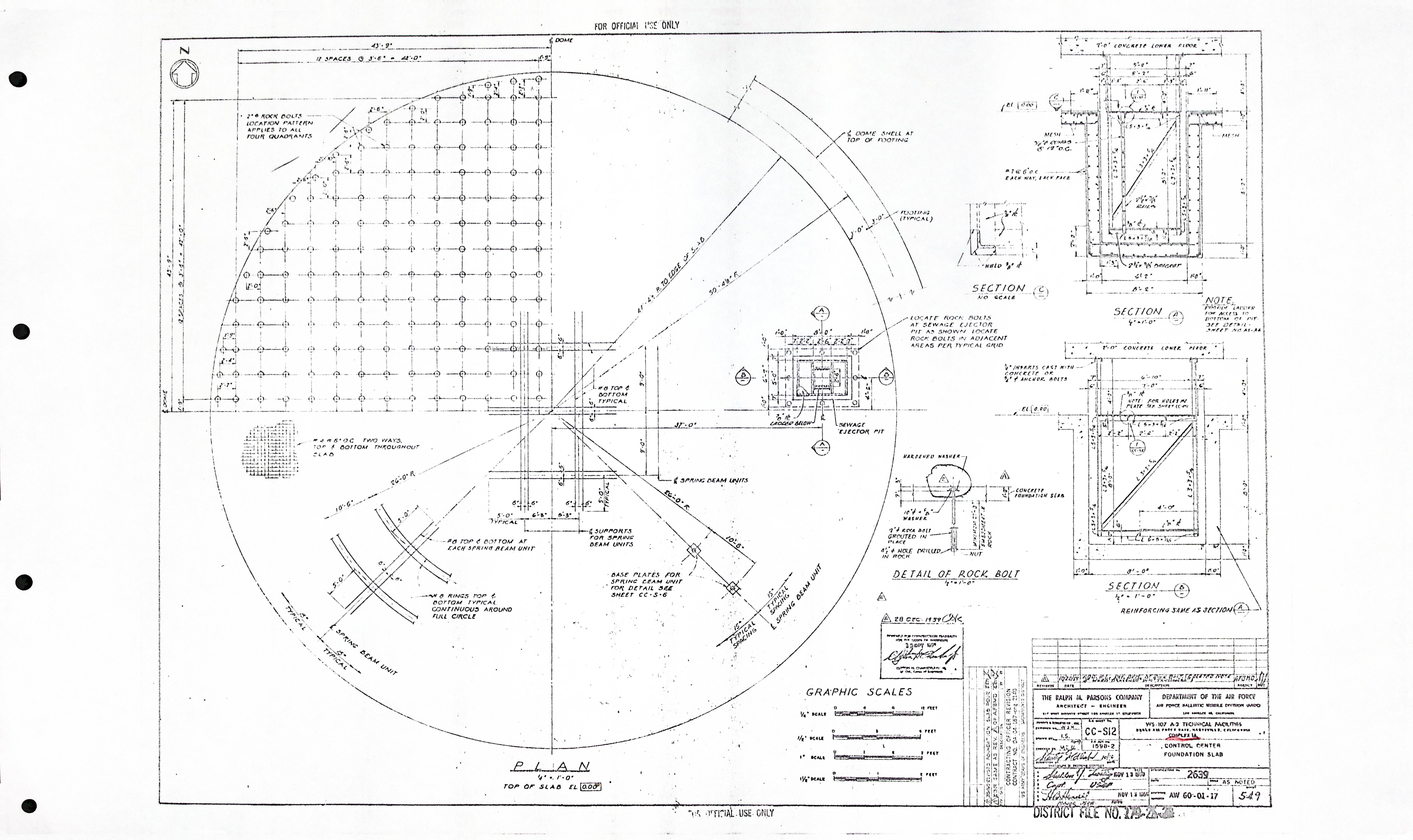
Control Center - Structural drawings (12)
| Drawing Number | Description |
|---|---|
| CC-S1 | TYPICAL CROSS SECTION |
| CC-S2 | DOME PLAN |
| CC-S3 | DOME SECTION |
| CC-S4 | TUNNEL OPENING |
| CC-S5 | FOUNDATION SLAB |
| CC-S6 | SPRING BEAMS |
| CC-S7 | LOWER FLOOR |
| CC-S8 | UPPER FLOOR FRAMING PLAN |
| CC-S9 | UPPER FLOOR - STEEL DETAILS |
| CC-S10 | UPPER FLOOR - STEEL DETAILS |
| CC-S11 | TYPICAL CROSS SECTION |
| CC-S12 | FOUNDATION SLAB |