Beale 851st SMS - General Blueprints

More Info

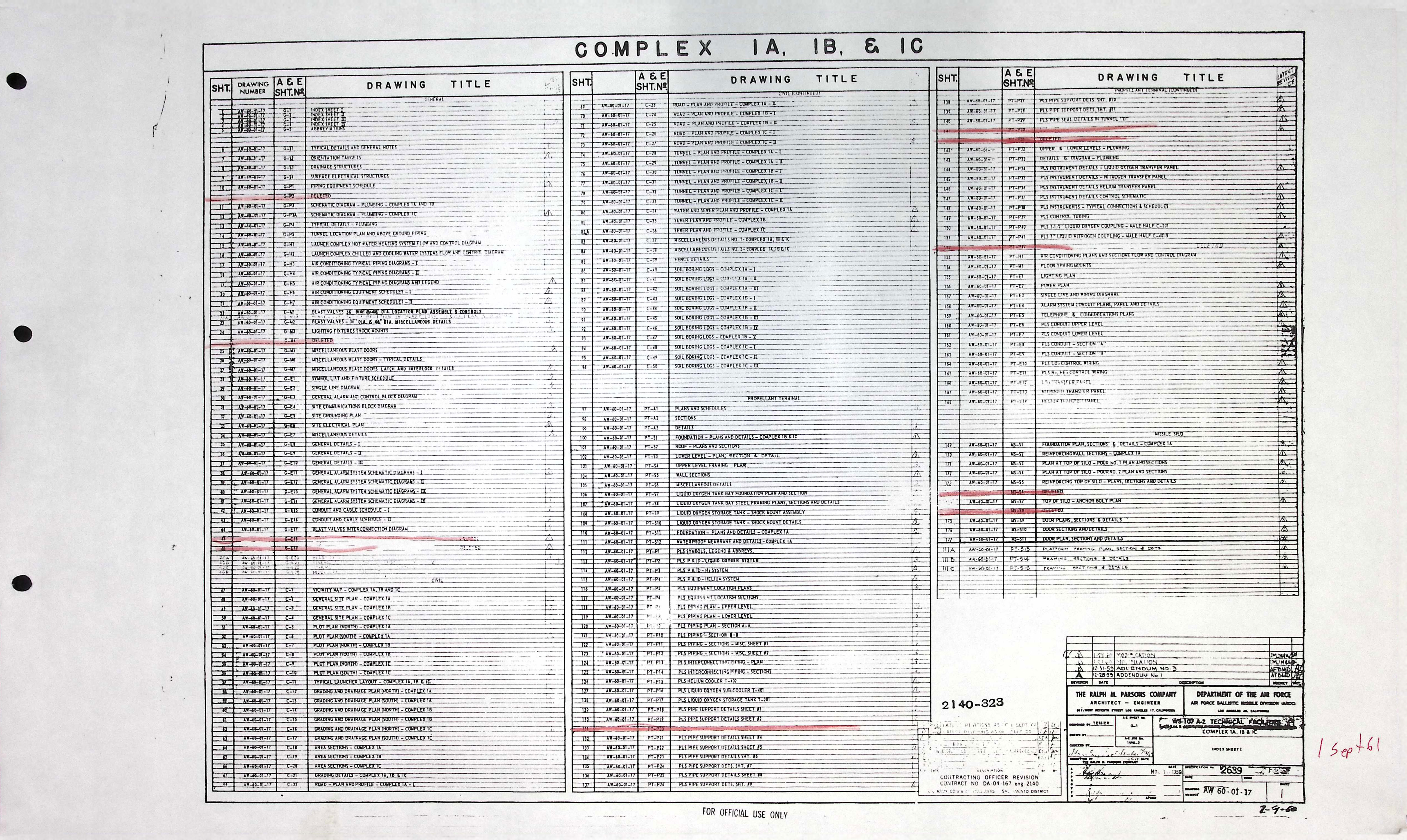
Any gaps in the list of drawings will be marked as either MISSING or DELETED. Missing drawings are simply ones I don't have, whereas deleted drawings were removed from the set by the drafting company or contractor. This latter group means that a drawing might exist, but was not part of the as-built set of final plans, or was later modified.

The General blueprints are further broken down into the following sub-groups as shown in the following table and can be directly selected below to jump to those groups of drawings.

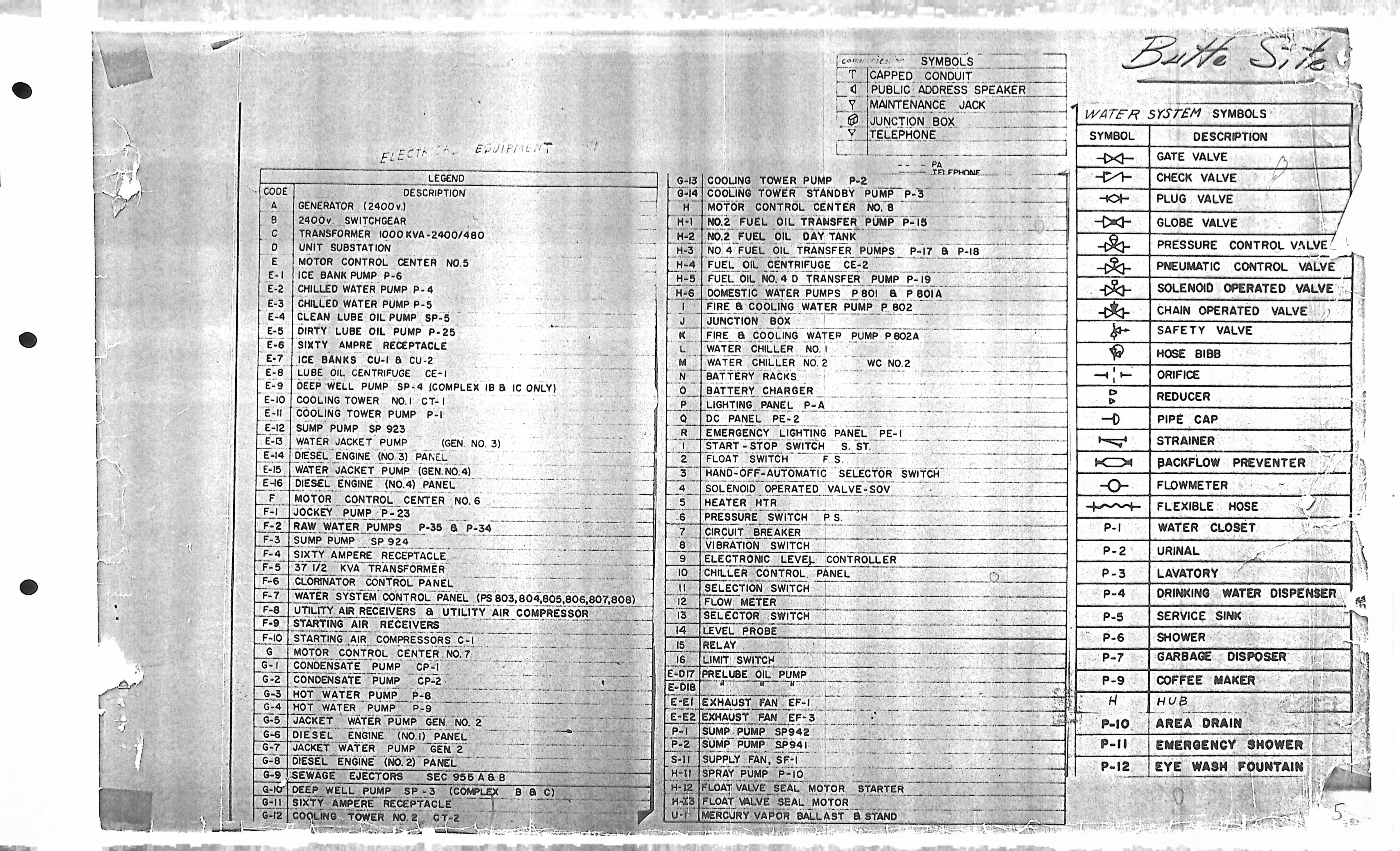
Additionally, the General blueprints also have their own set of general drawings that include the drawing indices and a separate symbol legend page for the Butte/Live Oak site (851-B) that is present in the table below under "G" and "SL".

At this time, there are no drawings available in the following sub-groups: Architectural, and Composite.

There are currently 77 drawings in the General Blueprints section.

NOTE: Drawing descriptions may be truncated and/or abbreviated to remove redundant text and maintain brevity in limited cell space.

Drawing Types

The following table provides quick selection of the types of drawings in the General section. You can choose a category below, or scroll down to see everything in order.

Sub-group Description
A Architectural
CP Composite
E Electrical
G Index
H HVAC
M Mechanical
P Plumbing/Piping
S Structural
SL Symbol Legend

General - Architectural drawings (0)

Drawing Number Description
-- N/A

General - Composite drawings (0)

Drawing Number Description
-- N/A

General - Electrical drawings (25)

Drawing Number Description
G-E1 SYMBOL LIST AND FIXTURE SCHEDULE
G-E2 SINGLE LINE DIAGRAM
G-E3 GENERAL ALARM & CONTROL BLOCK DIAGRAM
G-E4 SITE COMMUNICATIONS BLOCK DIAGRAM
G-E5 SITE GROUNDING PLAN
G-E6 SITE ELECTRICAL PLAN
G-E7 MISCELLANEOUS DETAILS
G-E8 GENERAL DETAILS - I
G-E9 GENERAL DETAILS - II
G-E10 GENERAL DETAILS - III
G-E11 GENERAL ALARM SYSTEM SCHEMATIC DIAGRAMS - I
G-E11 GENERAL ALARM SYSTEM SCHEMATIC DIAGRAMS - I *
G-E12 GENERAL ALARM SYSTEM SCHEMATIC DIAGRAMS - II
G-E13 GENERAL ALARM SYSTEM SCHEMATIC DIAGRAMS - III
G-E14 GENERAL ALARM SYSTEM SCHEMATIC DIAGRAMS - IV
G-E15 CONDUIT & CABLE SCHEDULE - I
G-E15 CONDUIT & CABLE SCHEDULE - I *
G-E16 CONDUIT & CABLE SCHEDULE - II
G-E17 BLAST VALVES INTERCONNECTION DIAGRAM
G-E18 DELETED
G-E19 DELETED
G-E20 BLAST DETECTION SYSTEM BLOCK DIAGRAMS
G-E21 GENERAL ALARM SYSTEM SCHEMATIC DIAGRAM V
G-E22 SCHEMATIC DIAGRAMS FOR ENGINE GENERATORS
G-E23 MISCELLANEOUS DETAILS II
G-E23 MISCELLANEOUS DETAILS II *

General - Index drawings (12)

Drawing Number Description
G-1 INDEX SHEET I
G-1 INDEX SHEET I *
G-1 INDEX SHEET I *
G-2 INDEX SHEET II
G-2 INDEX SHEET II *
G-3 INDEX SHEET III
G-3 INDEX SHEET III *
G-4 INDEX SHEET IV
G-4 INDEX SHEET IV *
G-5 ABBREVIATIONS
G-5 ABBREVIATIONS *

General - HVAC drawings (12)

Drawing Number Description
G-H1 LAUNCH COMPLEX HOT WATER HEATING SYSTEM FLOW & CONTROL DIAGRAM
G-H1 LAUNCH COMPLEX HOT WATER HEATING SYSTEM FLOW & CONTROL DIAGRAM *
G-H2 LAUNCH COMPLEX CHILLED & COOLING WATER SYSTEMS FLOW & CONTROL DIAGRAM
G-H2 LAUNCH COMPLEX CHILLED & COOLING WATER SYSTEMS FLOW & CONTROL DIAGRAM *
G-H3 AIR CONDITIONING TYPICAL PIPING DIAGRAMS - I
G-H3 AIR CONDITIONING TYPICAL PIPING DIAGRAMS - I *
G-H4 AIR CONDITIONING TYPICAL PIPING DIAGRAMS - II
G-H5 AIR CONDITIONING TYPICAL PIPING DIAGRAMS & LEGEND
G-H5 AIR CONDITIONING TYPICAL PIPING DIAGRAMS & LEGEND *
G-H6 AIR CONDITIONING EQUIPMENT SCHEDULES I
G-H7 AIR CONDITIONING EQUIPMENT SCHEDULES II

General - Mechanical drawings (14)

Drawing Number Description
G-M1 BLAST VALVES 36" DIA. & 48" DIA. LOCATION PLAN ASSEMBLY & CONTROLS
G-M1 BLAST VALVES 36" DIA. & 48" DIA. LOCATION PLAN ASSEMBLY & CONTROLS *
G-M1A BLAST VALVE 36" DIA. REDESIGN IN BLAST LOCKS 1 & 2 PLANS & SECTIONS
G-M1A BLAST VALVE 36" DIA. REDESIGN IN BLAST LOCKS 1 & 2 PLANS & SECTIONS *
G-M1B POWERHOUSE EXHAUST FACILITY BLAST VALVE - 48" DIA. - DUST COVER
G-M2 BLAST VALVES 36" DIA. & 48" DIA. MISC DETAILS
G-M2 BLAST VALVES 36" DIA. & 48" DIA. MISC DETAILS *
G-M3 LIGHTING FIXTURES SHOCK MOUNTS
G-M4 DELETED
G-M5 MISCELLANEOUS BLAST DOORS
G-M6 MISCELLANEOUS BLAST DOORS TYPICAL DETAILS
G-M7 MISCELLANEOUS BLAST DOORS LATCH & INTERLOCK DETAILS
G-M7 MISCELLANEOUS BLAST DOORS LATCH & INTERLOCK DETAILS *

General - Plumbing/Piping drawings (9)

Drawing Number Description
G-P1 PIPING EQUIPMENT SCHEDULE
G-P1 PIPING EQUIPMENT SCHEDULE *
G-P2 DELETED
G-P3 SCHEMATIC DIAGRAM PLUMBING
G-P3 SCHEMATIC DIAGRAM PLUMBING *
G-P4 TYPICAL DETAILS PLUMBING
G-P4 TYPICAL DETAILS PLUMBING *
G-P5 TUNNEL LOCATION PLAN & ABOVE GROUND PIPING
G-P5 TUNNEL LOCATION PLAN & ABOVE GROUND PIPING *

General - Structural drawings (4)

Drawing Number Description
G-S1 TYPICAL DETAILS & GENERAL NOTES
G-S2 ORIENTATION TARGETS
G-S3 DRAINAGE STRUCTURES
G-S4 SURFACE ELECTRICAL STRUCTURES

General - Symbol Legend (1)

Drawing Number Description
Legend GENERAL SYMBOL LEGEND - BUTTE SITE (851-B)
* This drawing is a duplicate of another with the same drawing number. Duplicates may comprise an earlier or later revision of the same drawing, or may simply be a separate copy with different markings or in different condition.