Equipment Terminal - Architectural drawings (4)
| Drawing Number | Description |
|---|---|
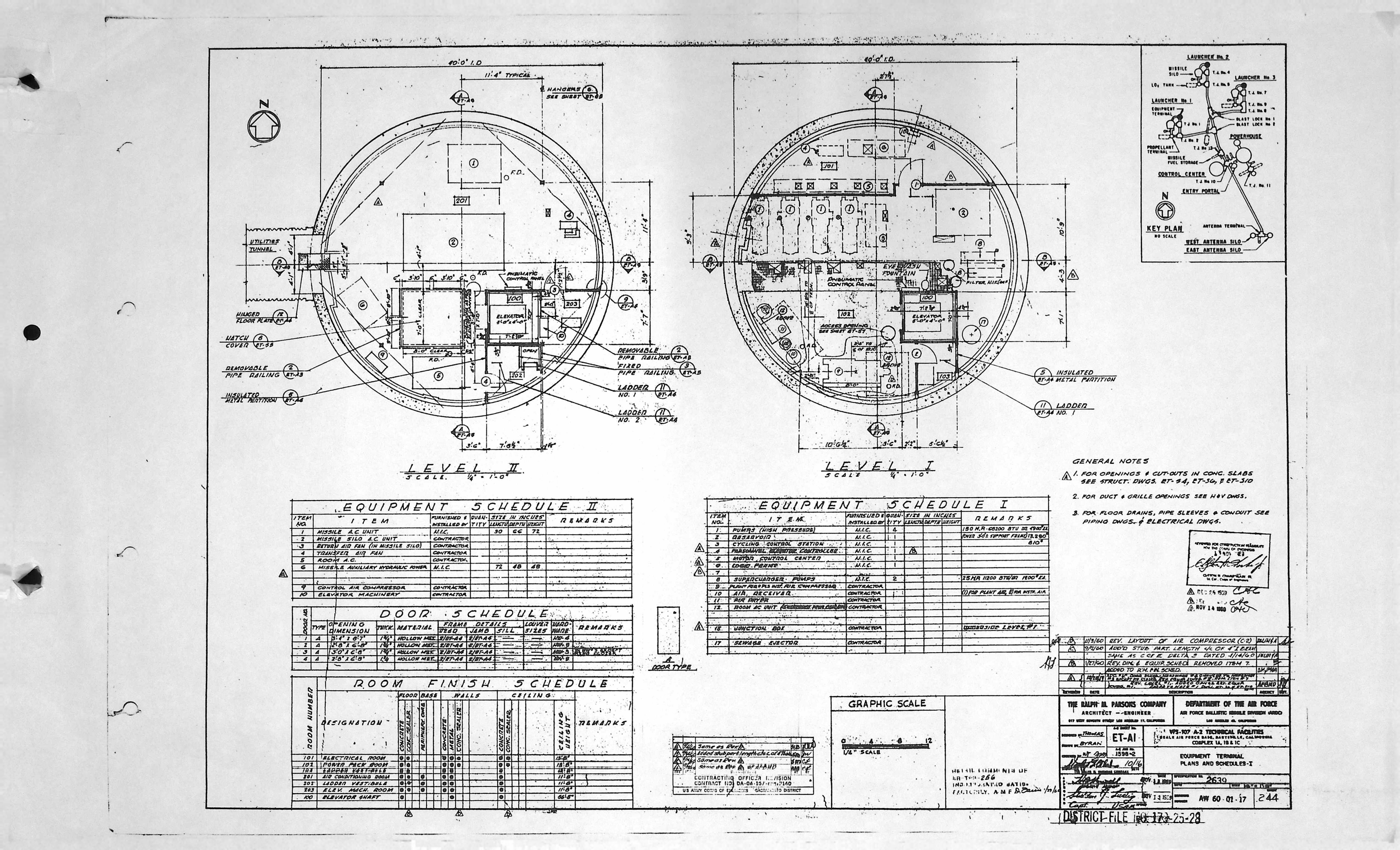
| ET-A1 | PLANS & SCHEDULES - I |
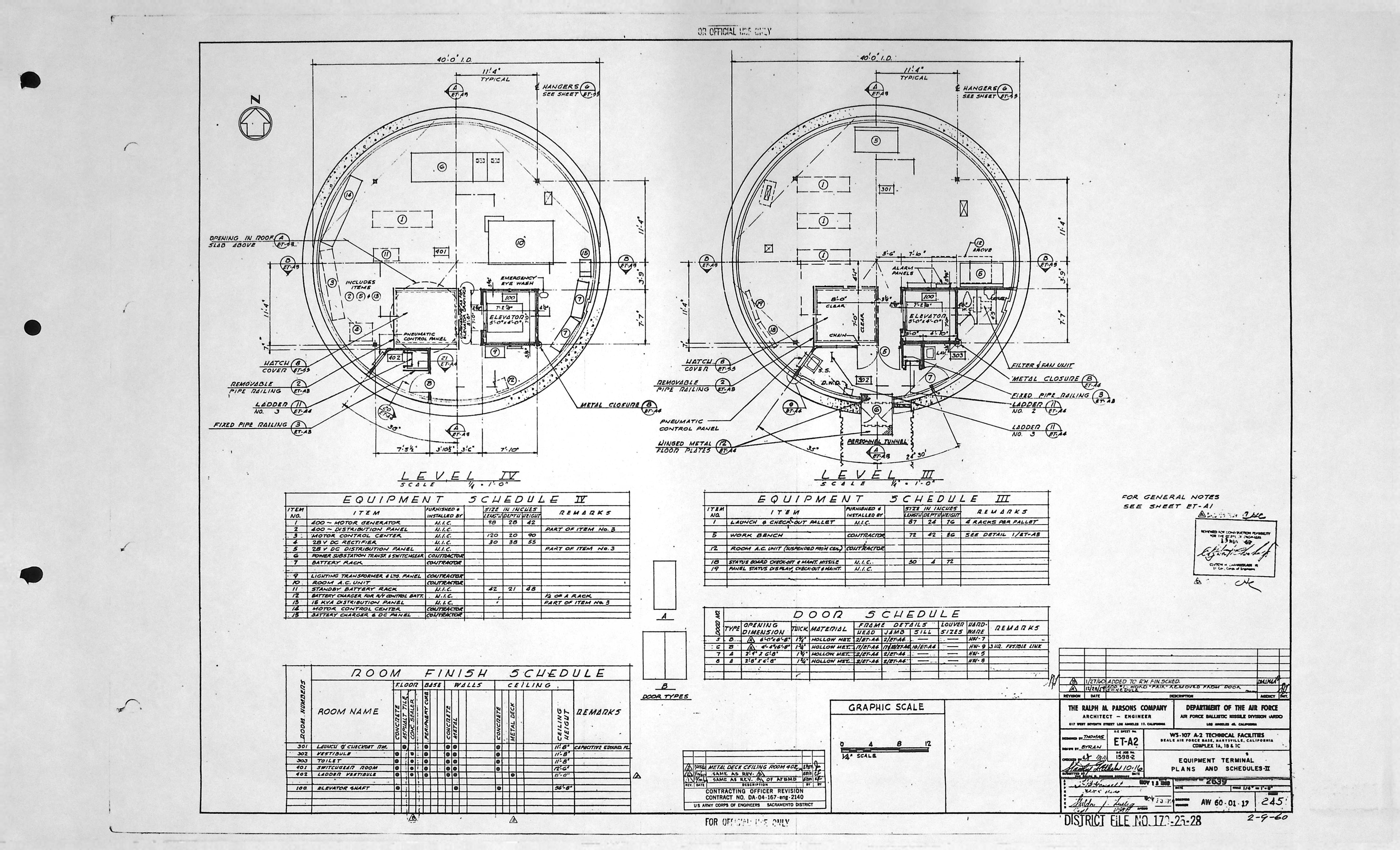
| ET-A2 | PLANS & SCHEDULES - II |
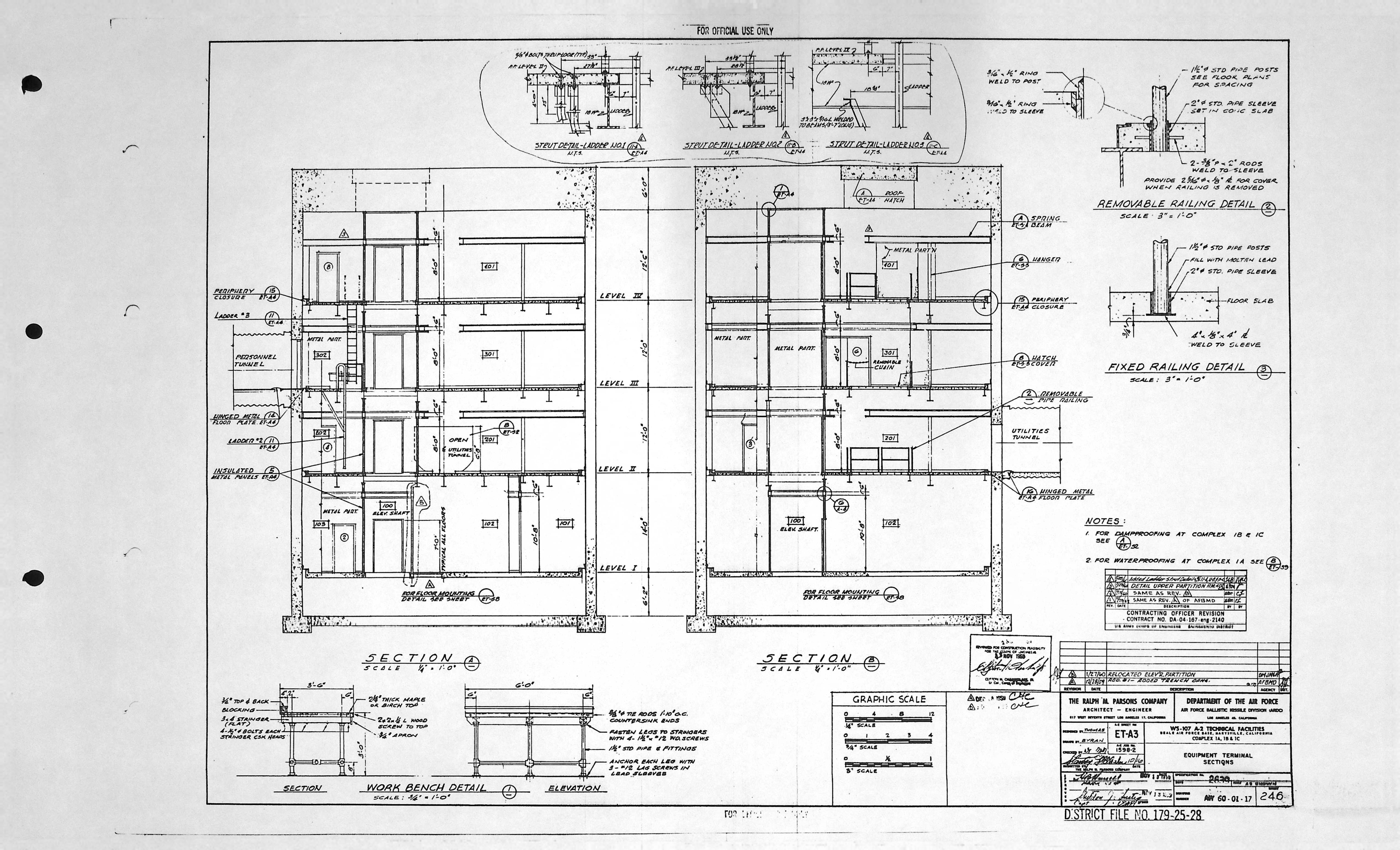
| ET-A3 | SECTIONS |
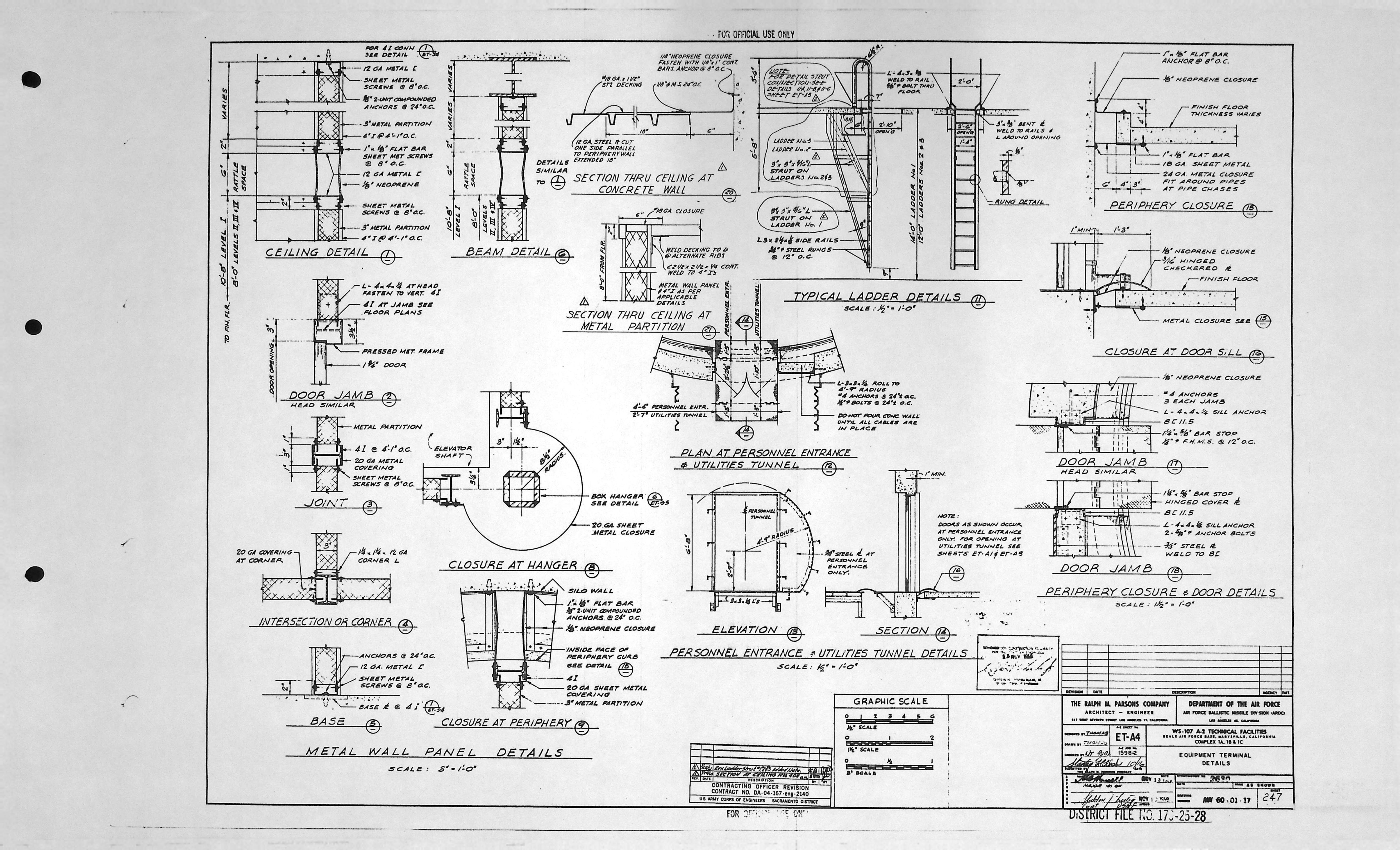
| ET-A4 | DETAILS |
Equipment Terminal - Composite drawings (0)
| Drawing Number | Description |
|---|---|
| -- | N/A |
Equipment Terminal - Electrical drawings (8)
| Drawing Number | Description |
|---|---|
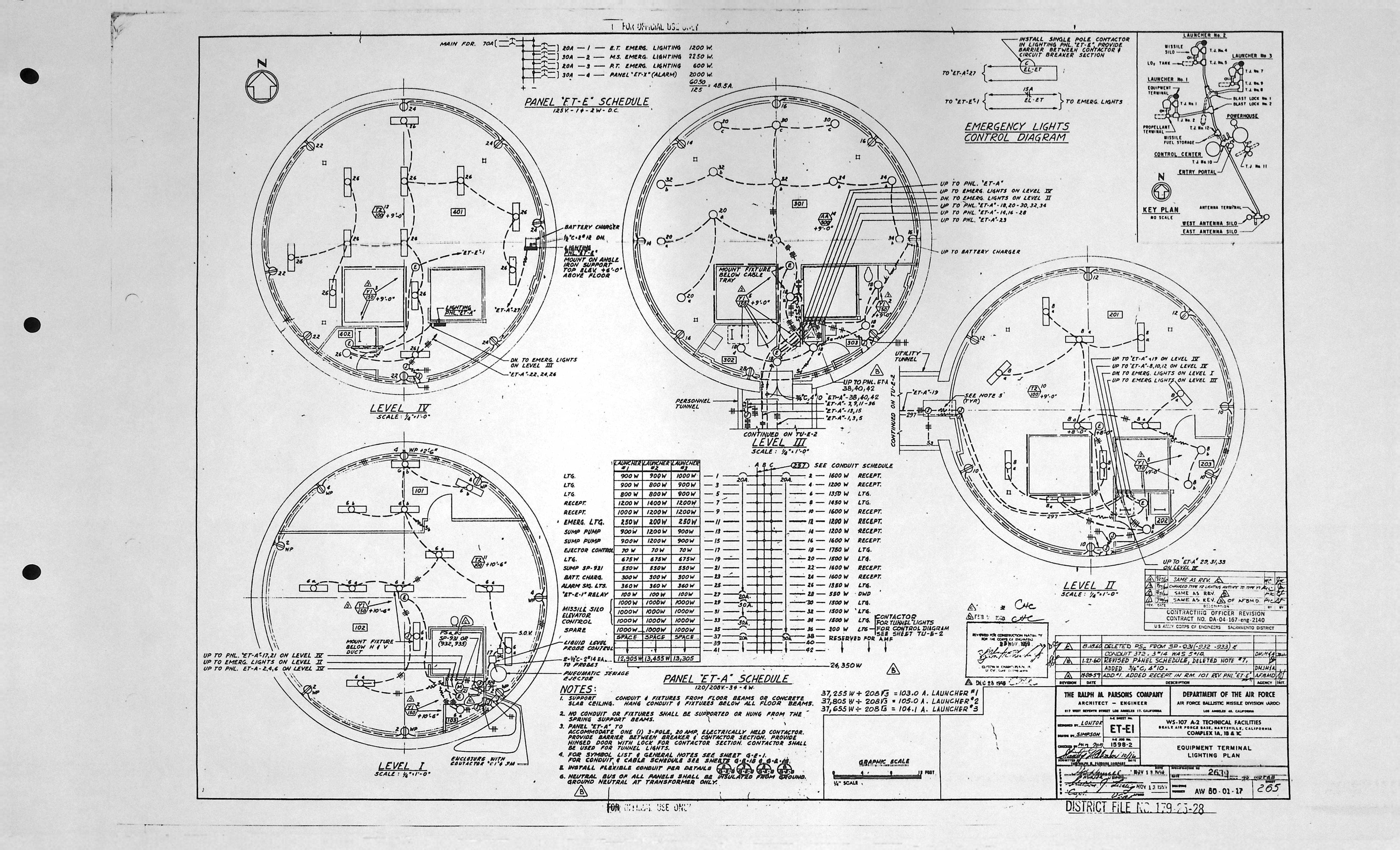
| ET-E1 | LIGHTING PLAN |
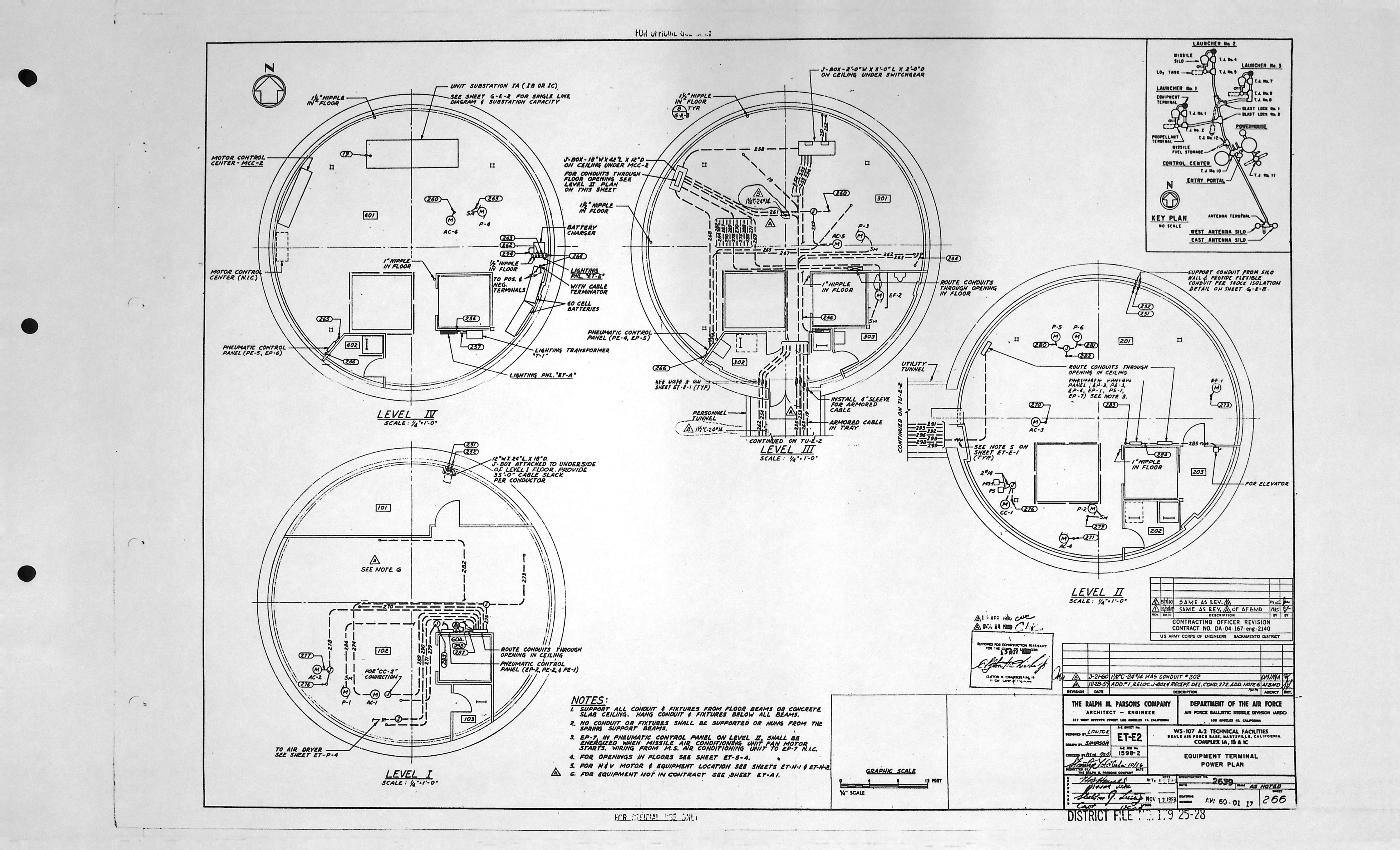
| ET-E2 | POWER PLAN |
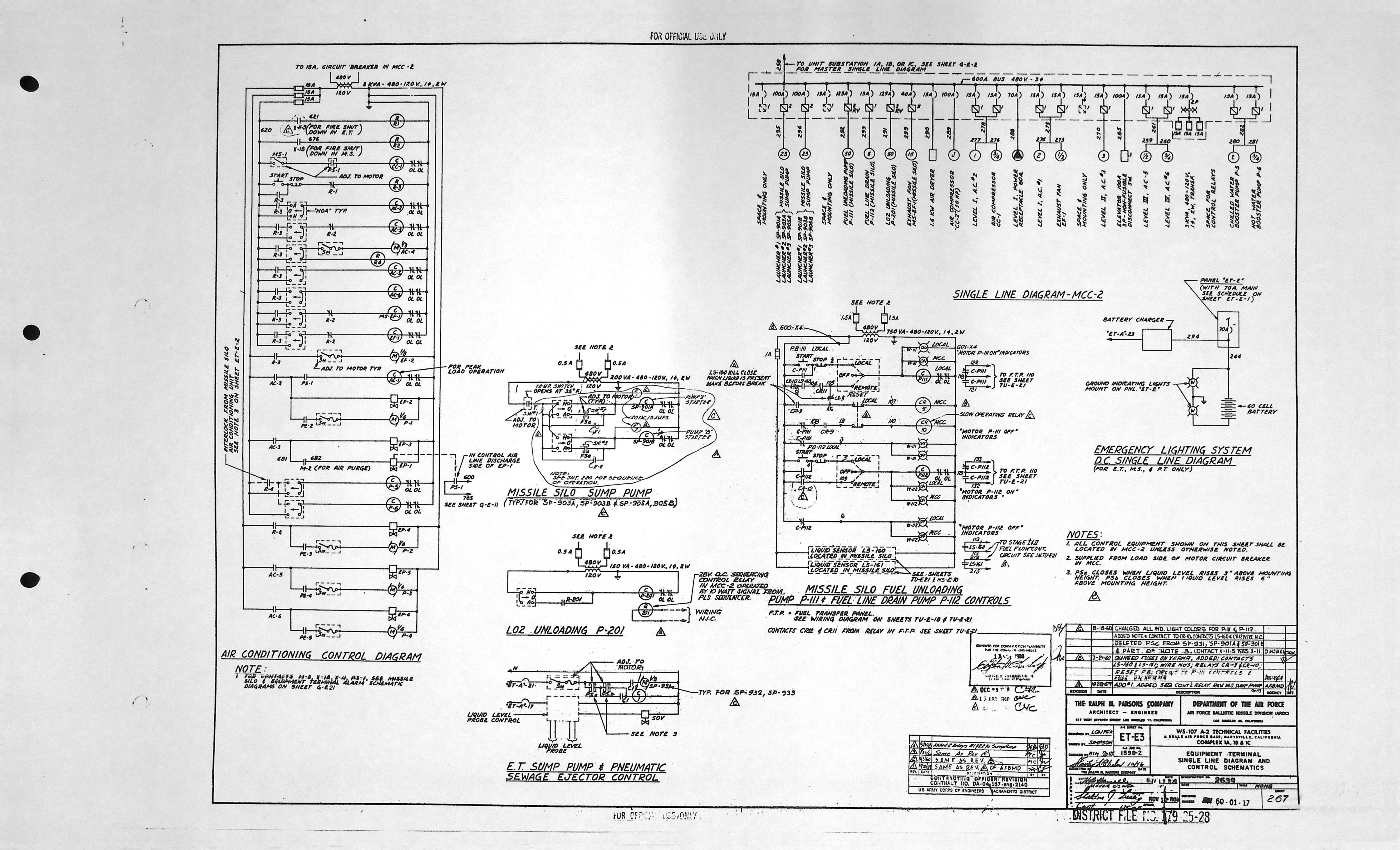
| ET-E3 | SINGLE LINE DIAGRAM & CONTROL SCHEMATICS |
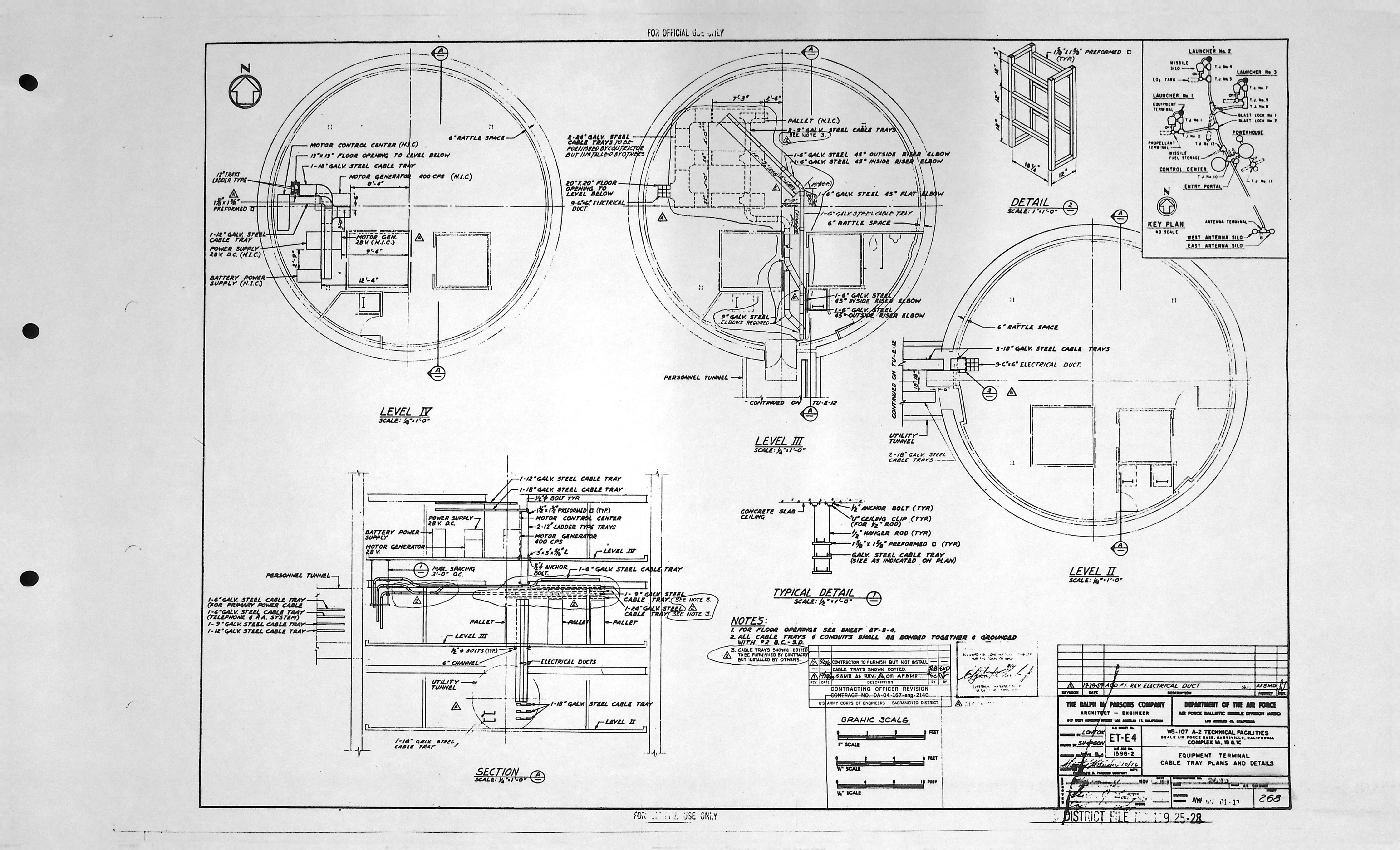
| ET-E4 | CABLE TRAY PLANS & DETAILS |
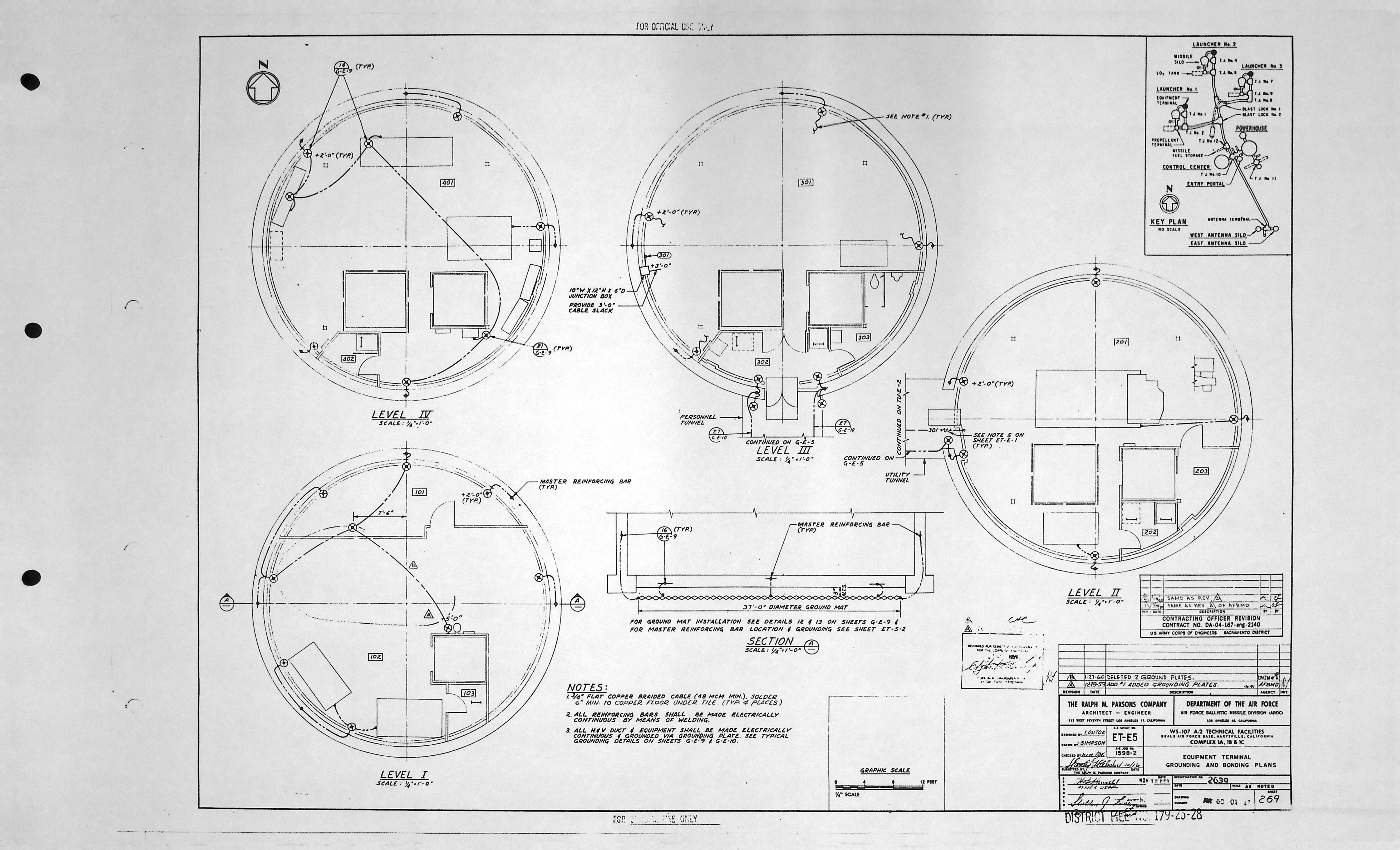
| ET-E5 | GROUNDING & BONDING PLANS |
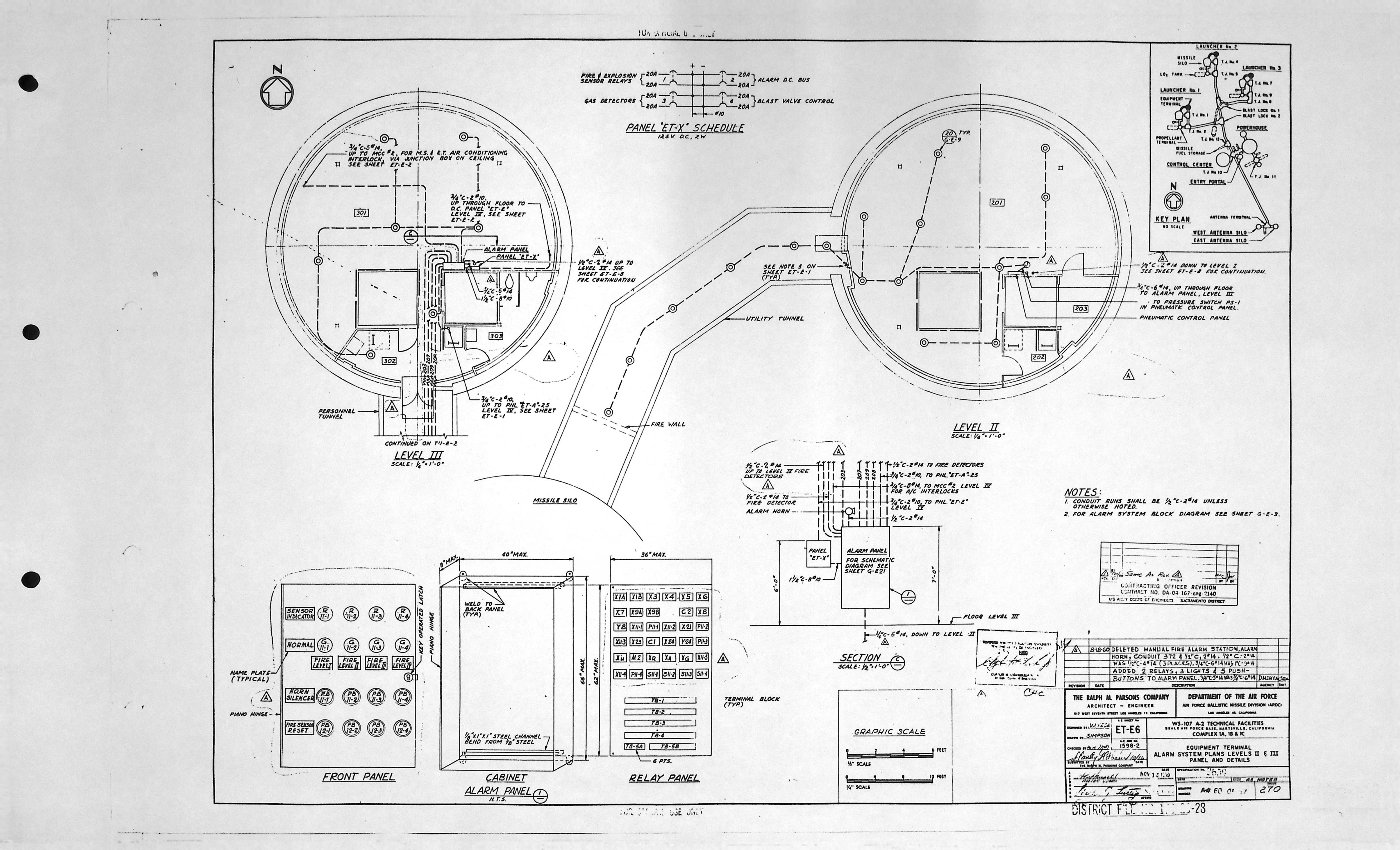
| ET-E6 | ALARM SYSTEM PLANS LEVELS II & III PANEL & DETAILS |
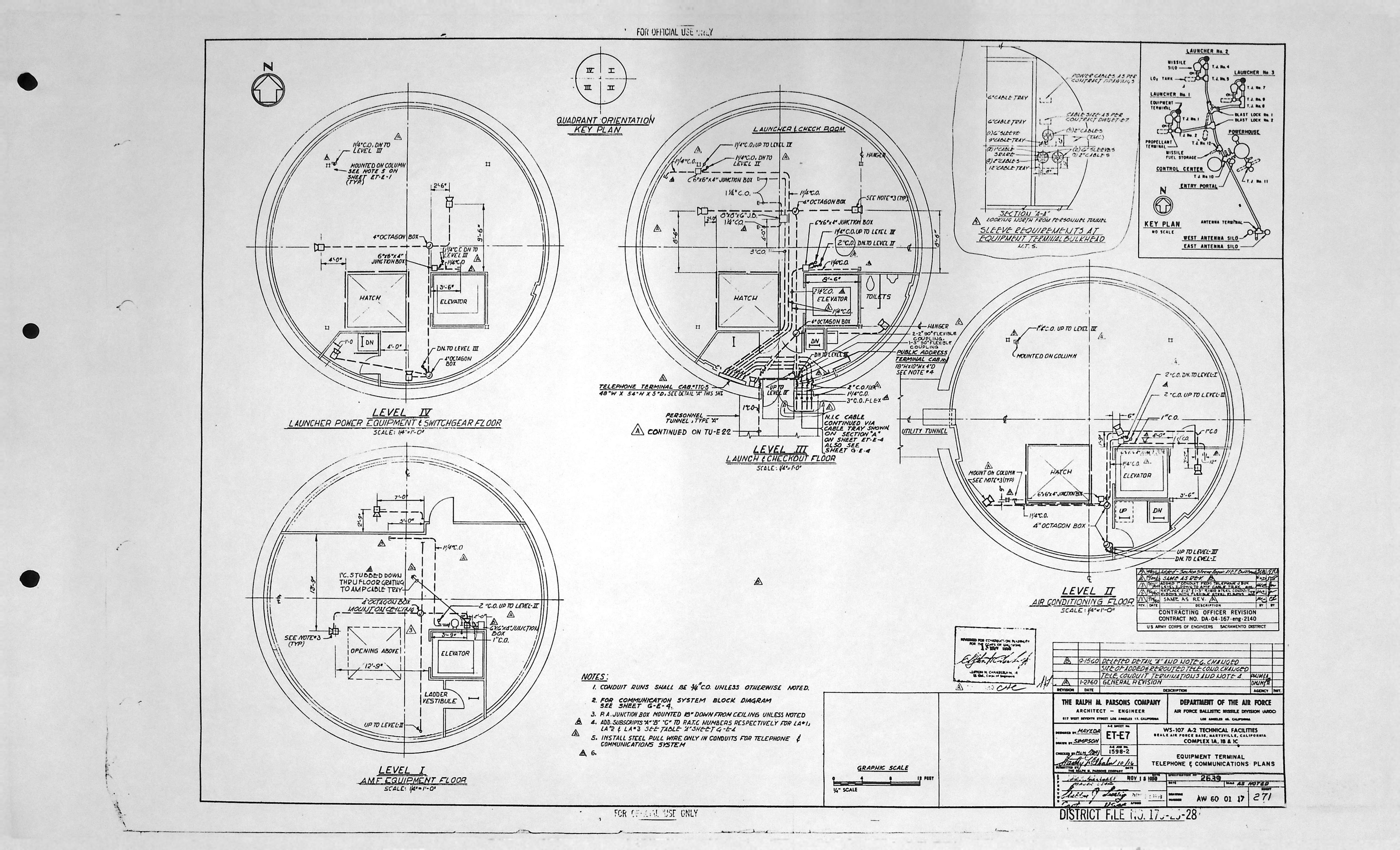
| ET-E7 | TELEPHONE & COMMUNICATIONS PLANS |
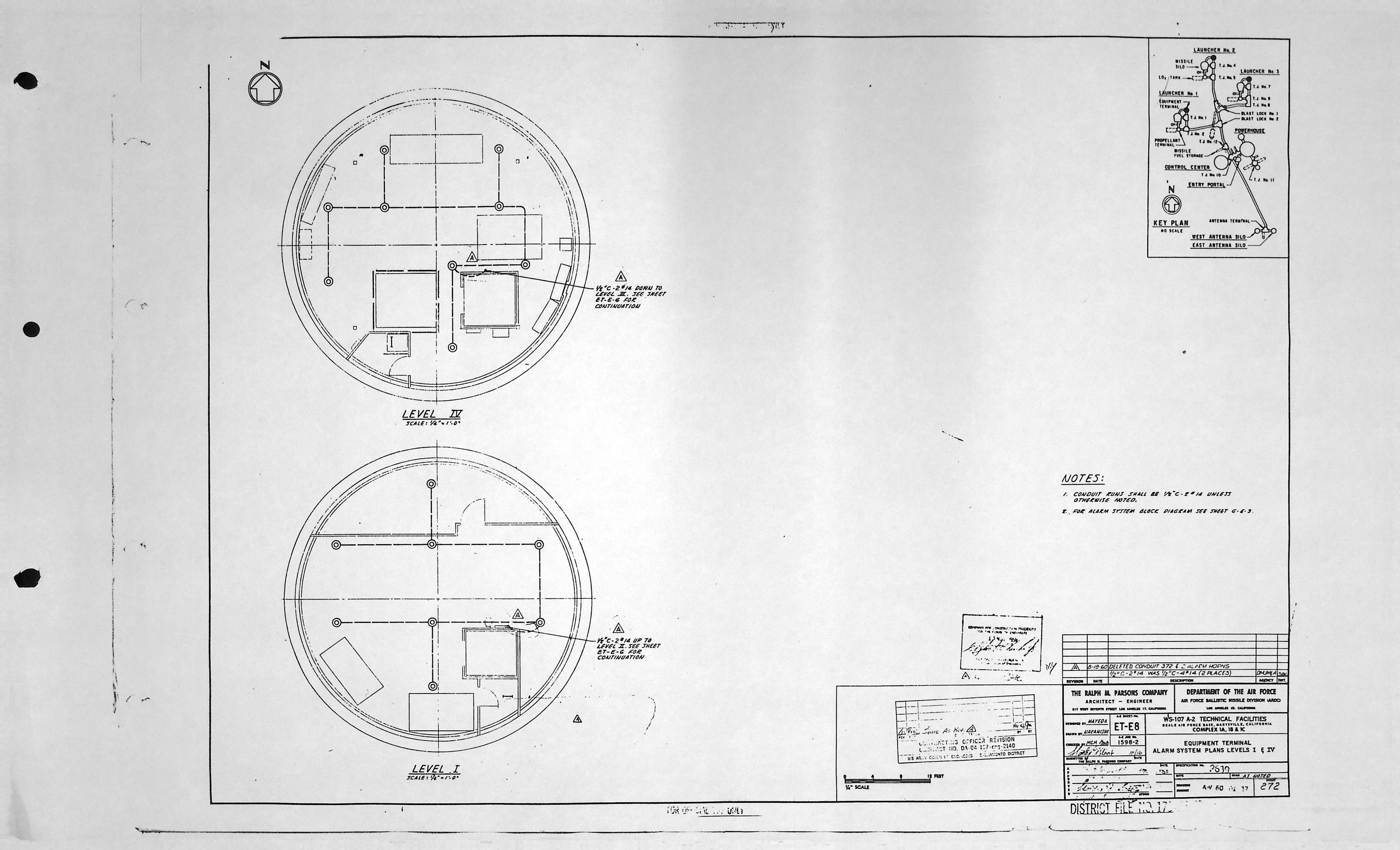
| ET-E8 | ALARM SYSTEM PLANS LEVELS I & IV |
Equipment Terminal - HVAC drawings (6)
| Drawing Number | Description |
|---|---|
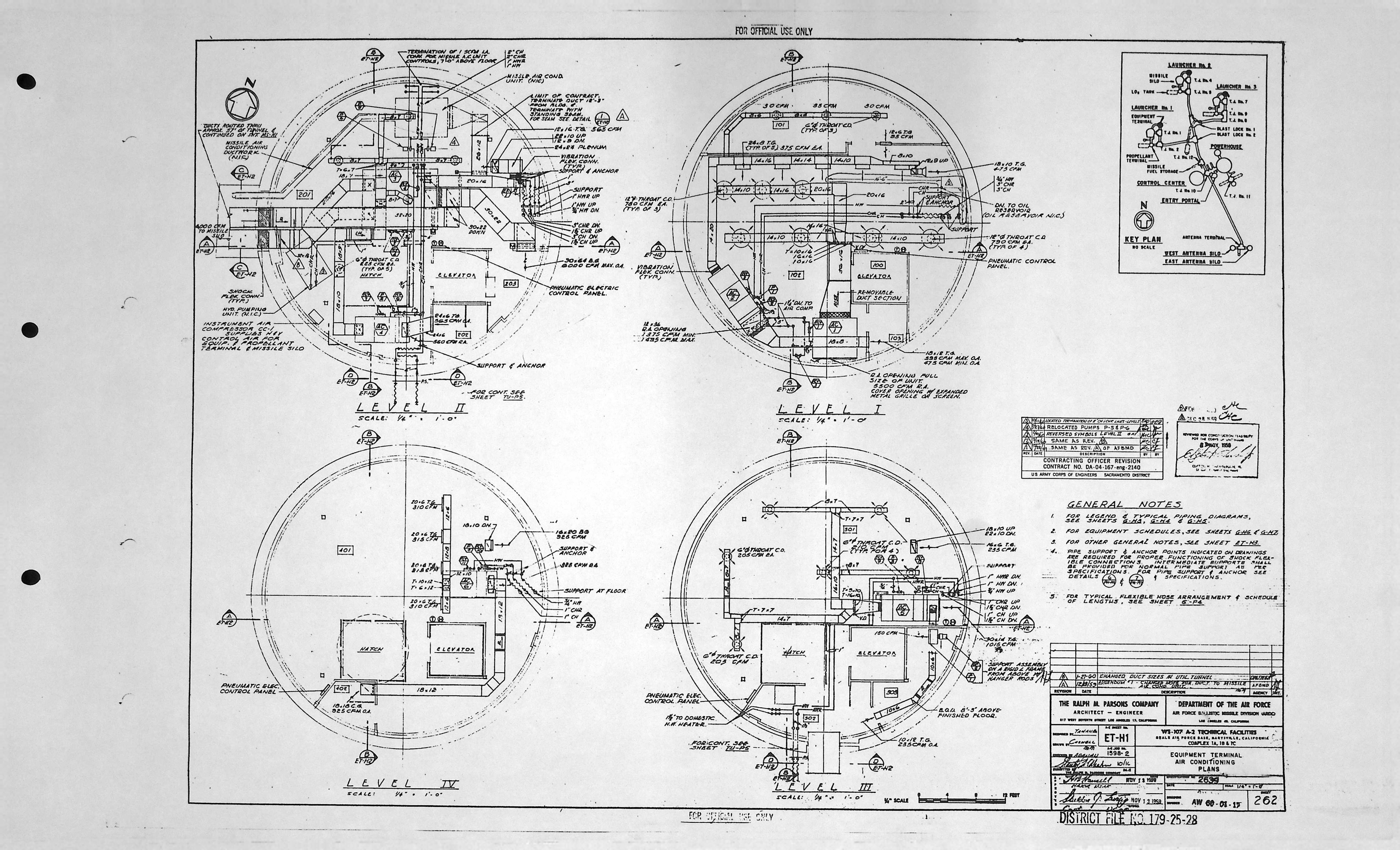
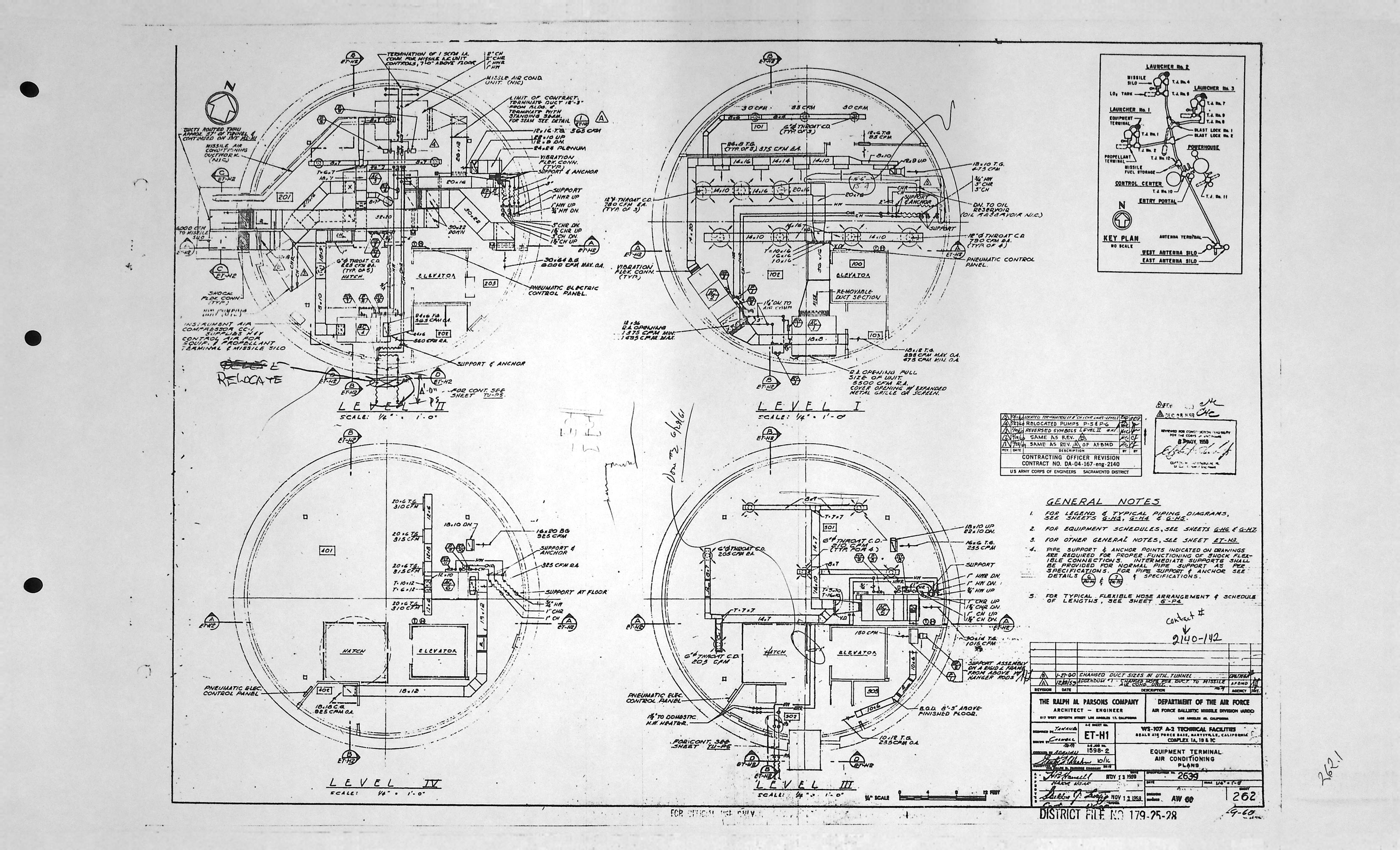
| ET-H1 | AIR CONDITIONING PLANS |
| ET-H1 | AIR CONDITIONING PLANS * |
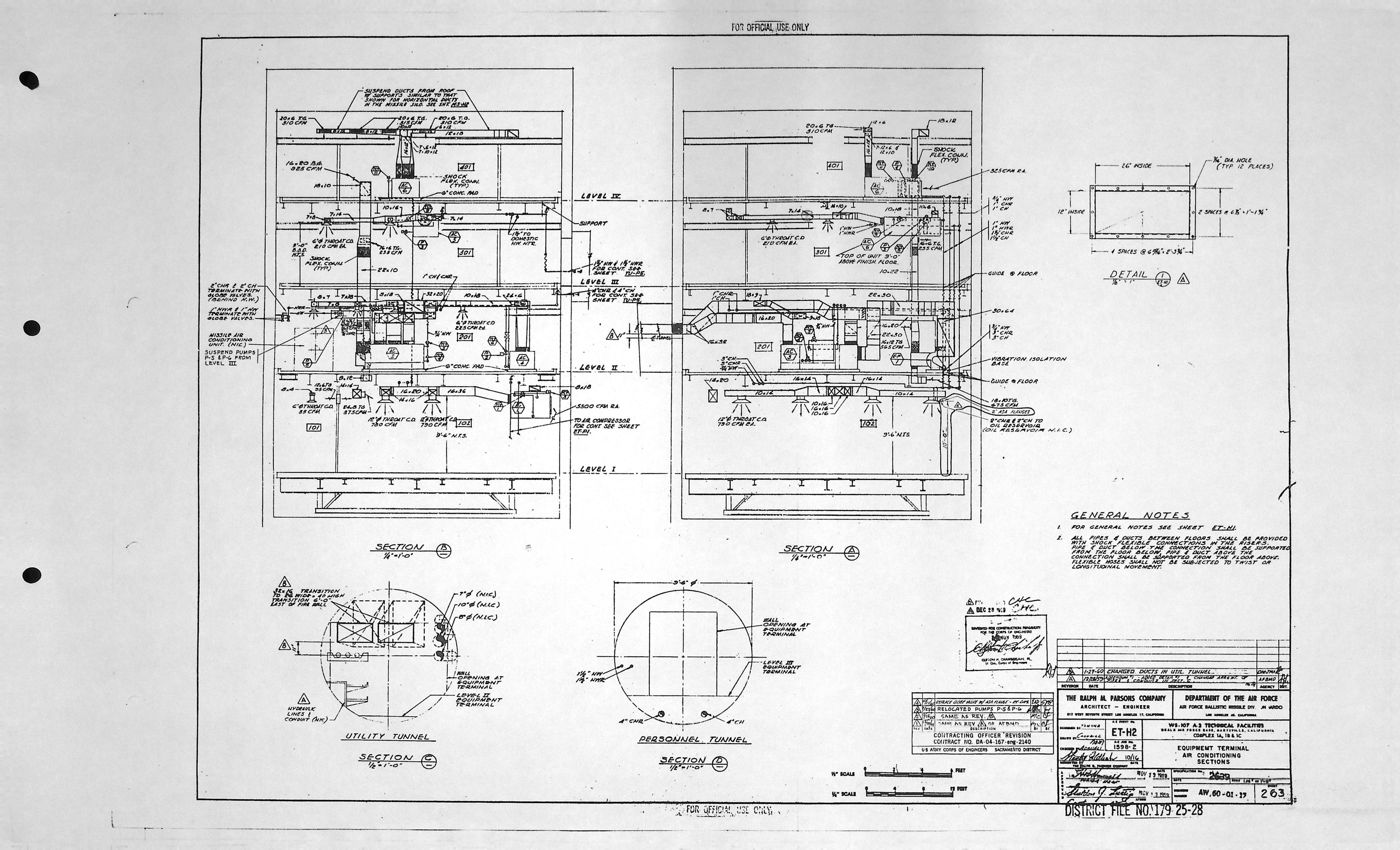
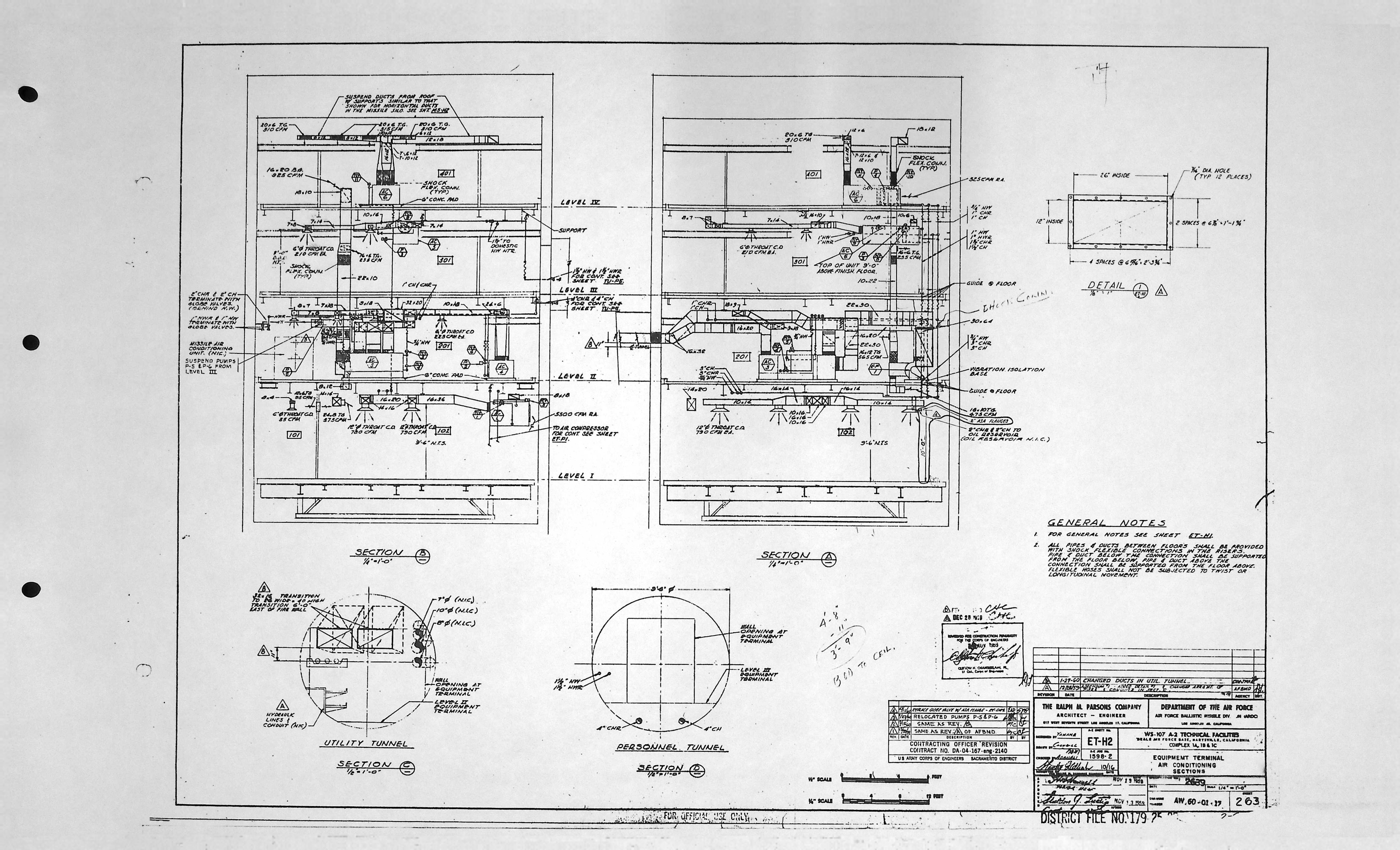
| ET-H2 | AIR CONDITIONING SECTIONS |
| ET-H2 | AIR CONDITIONING SECTIONS * |
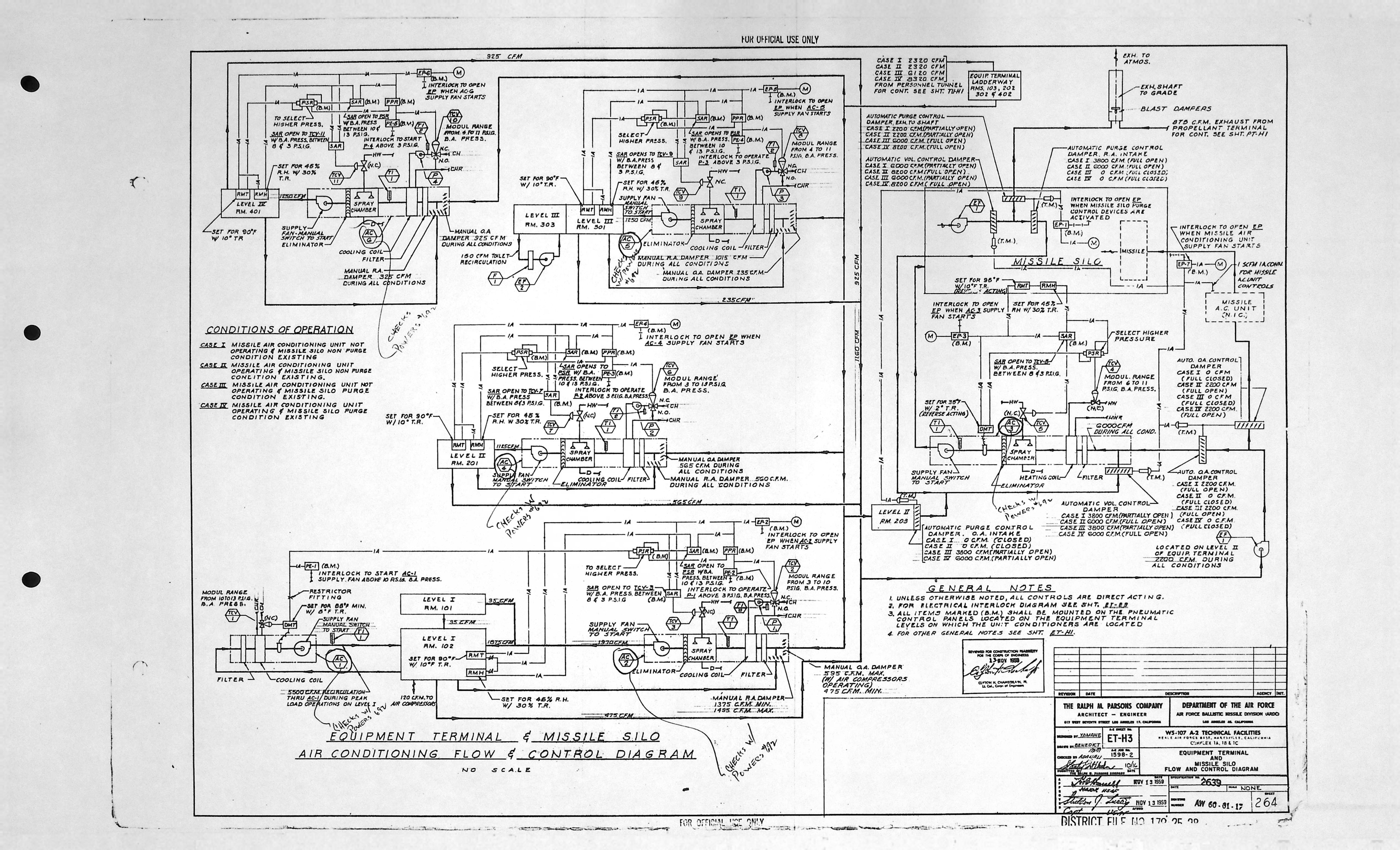
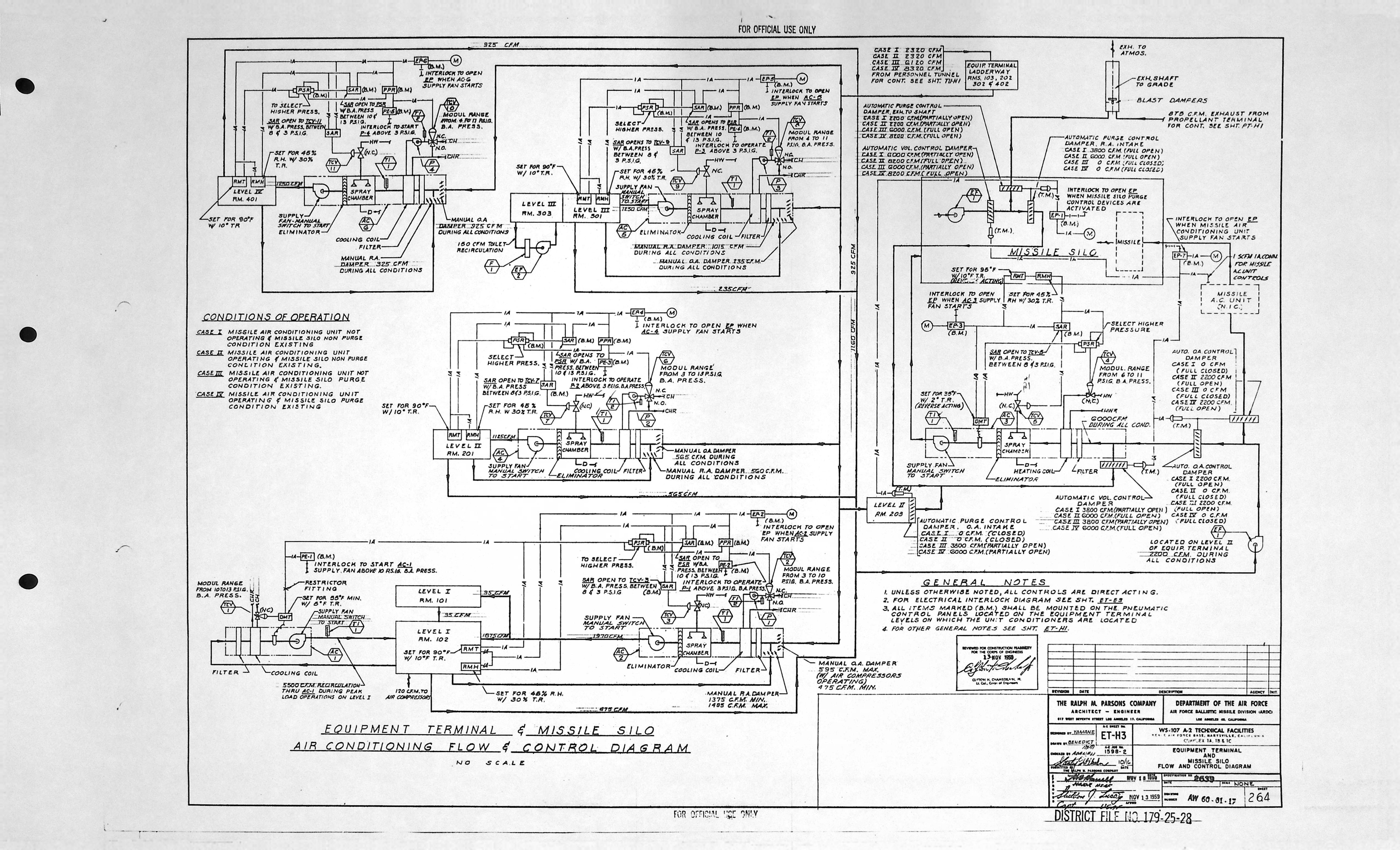
| ET-H3 | EQUIPMENT TERMINAL & MISSILE SILO FLOW & CONTROL DIAGRAM |
| ET-H3 | EQUIPMENT TERMINAL & MISSILE SILO FLOW & CONTROL DIAGRAM * |
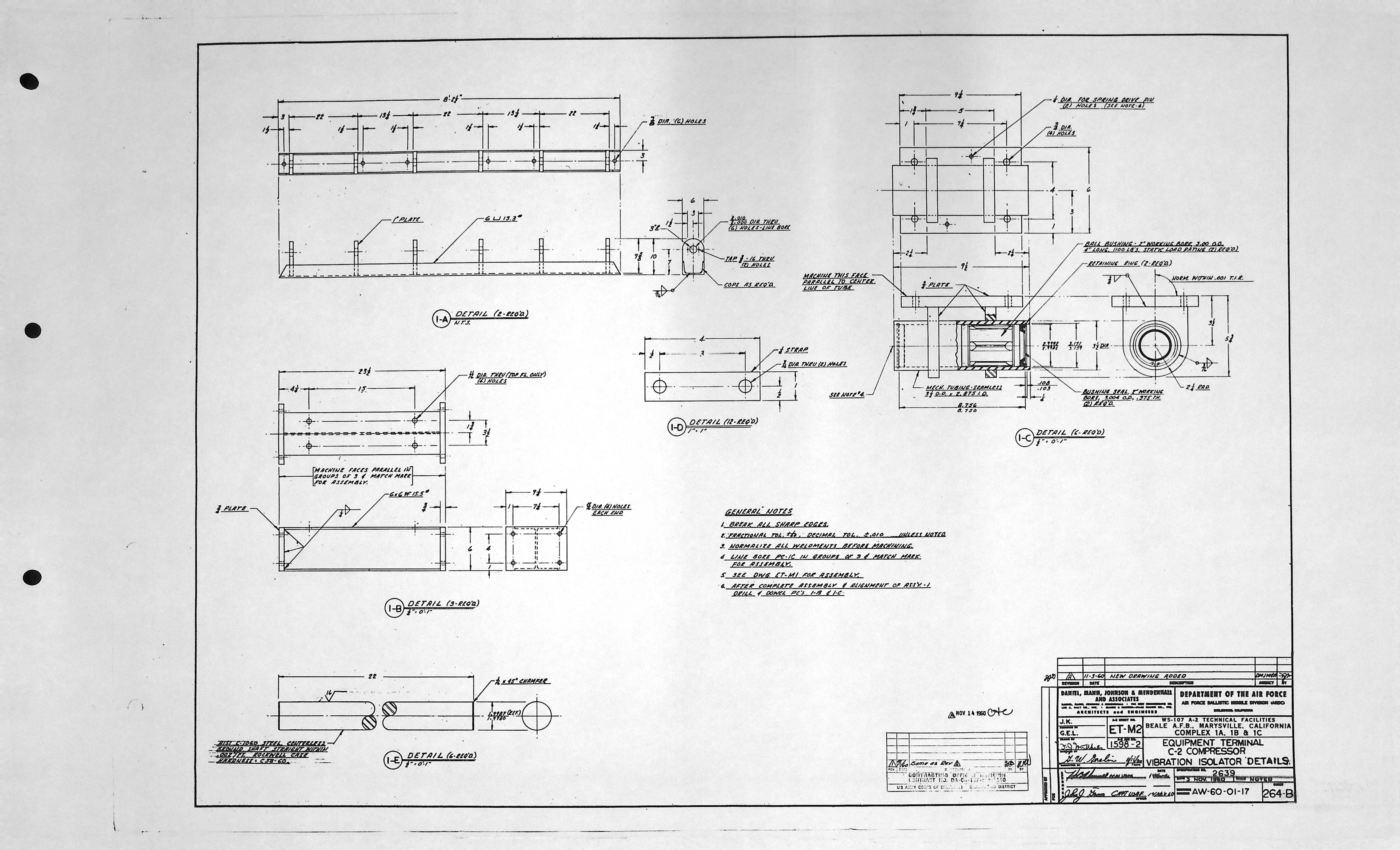
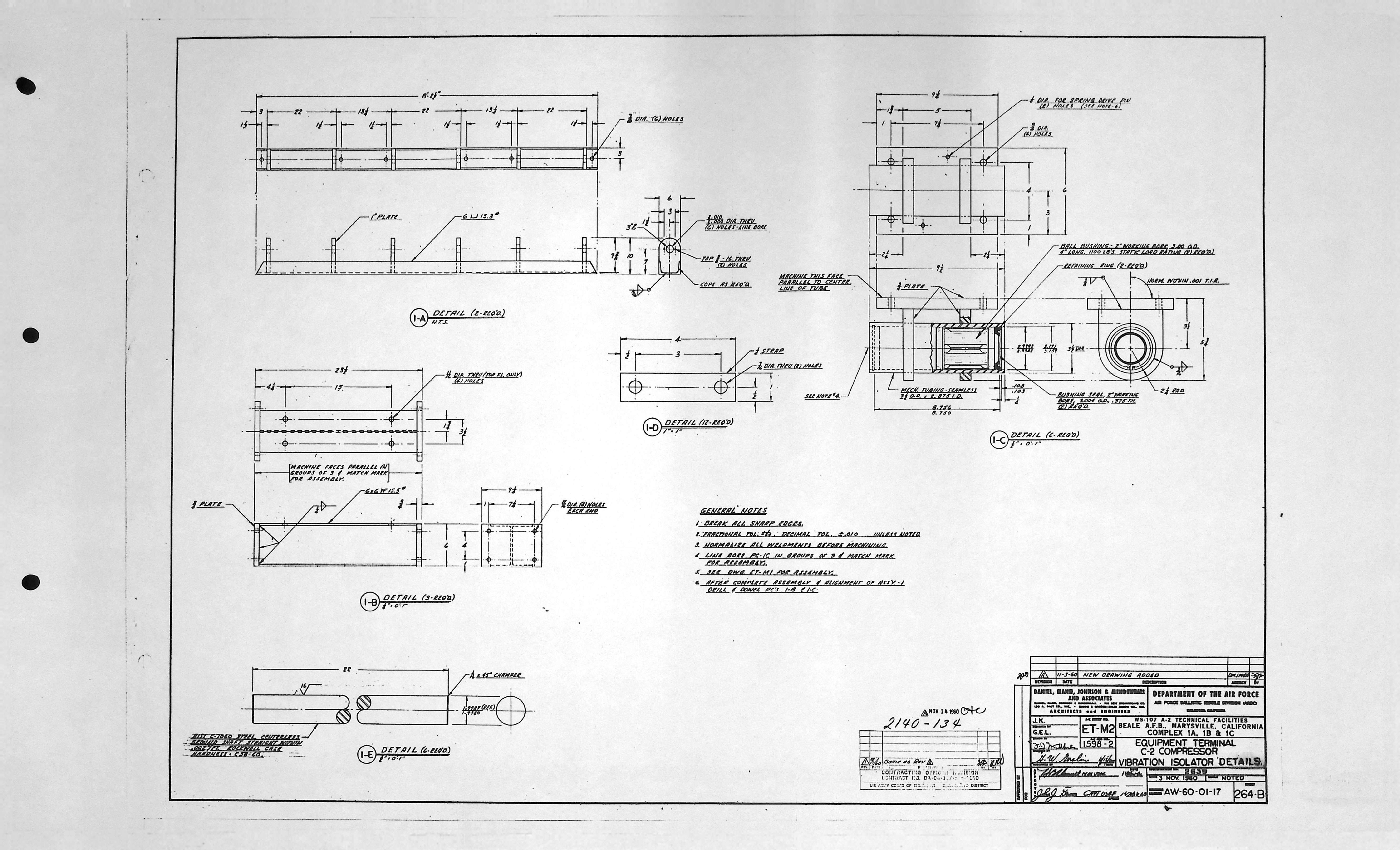
Equipment Terminal - Mechanical drawings (4)
| Drawing Number | Description |
|---|---|
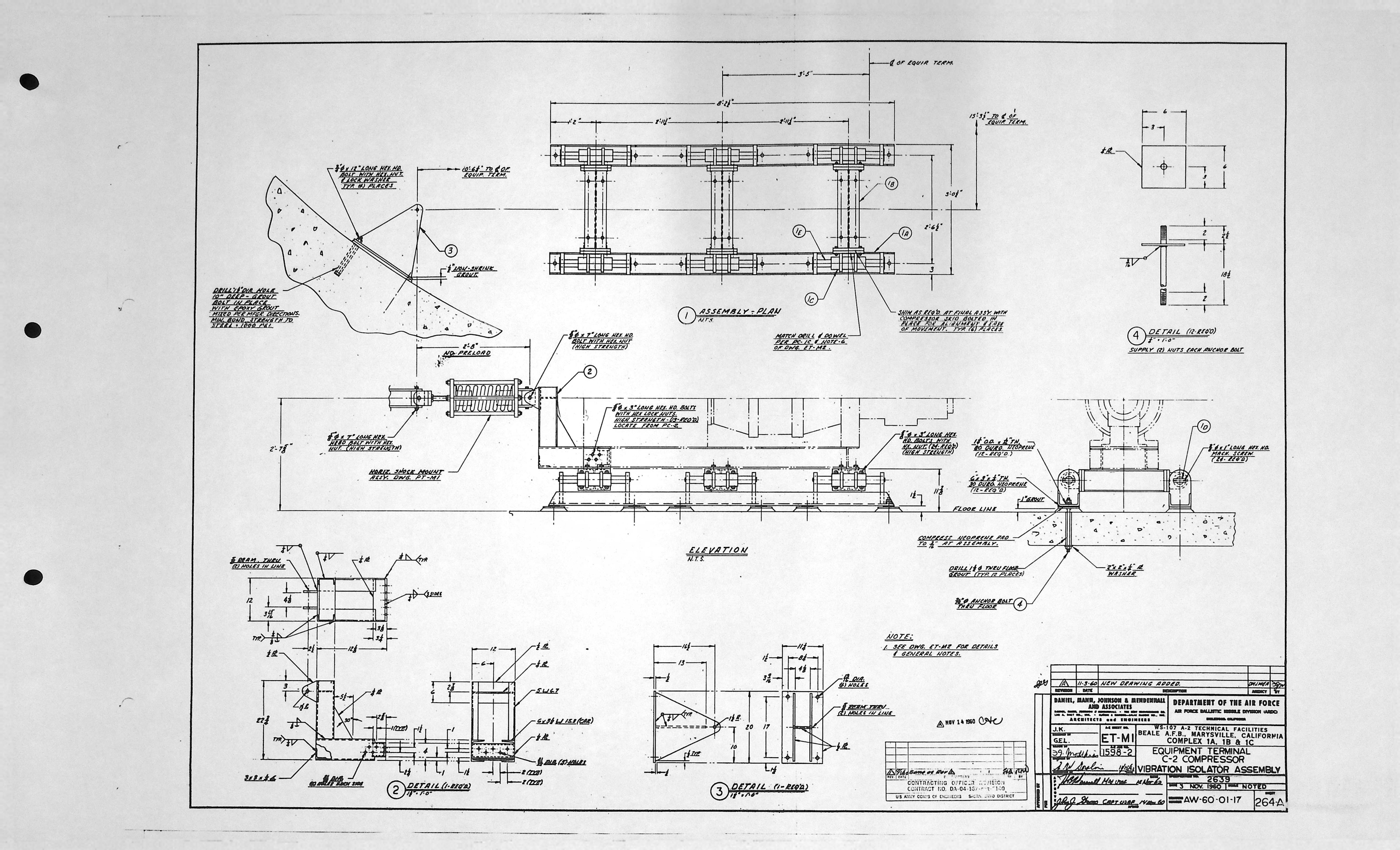
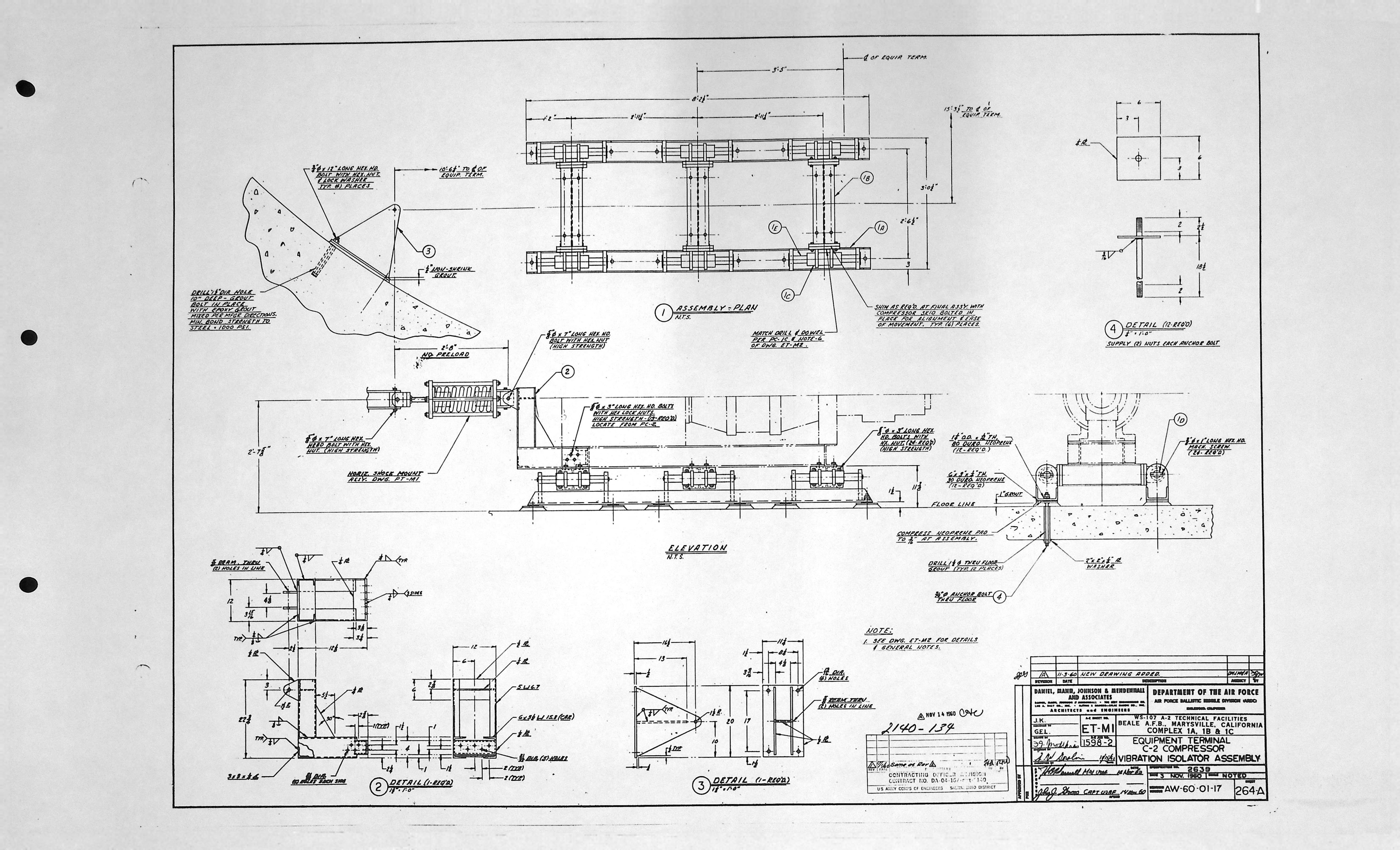
| ET-M1 | C-2 COMPRESSOR VIBRATION ISOLATOR ASSEMBLY |
| ET-M1 | C-2 COMPRESSOR VIBRATION ISOLATOR ASSEMBLY * |
| ET-M2 | C-2 COMPRESSOR VIBRATION ISOLATOR DETAILS |
| ET-M2 | C-2 COMPRESSOR VIBRATION ISOLATOR DETAILS * |
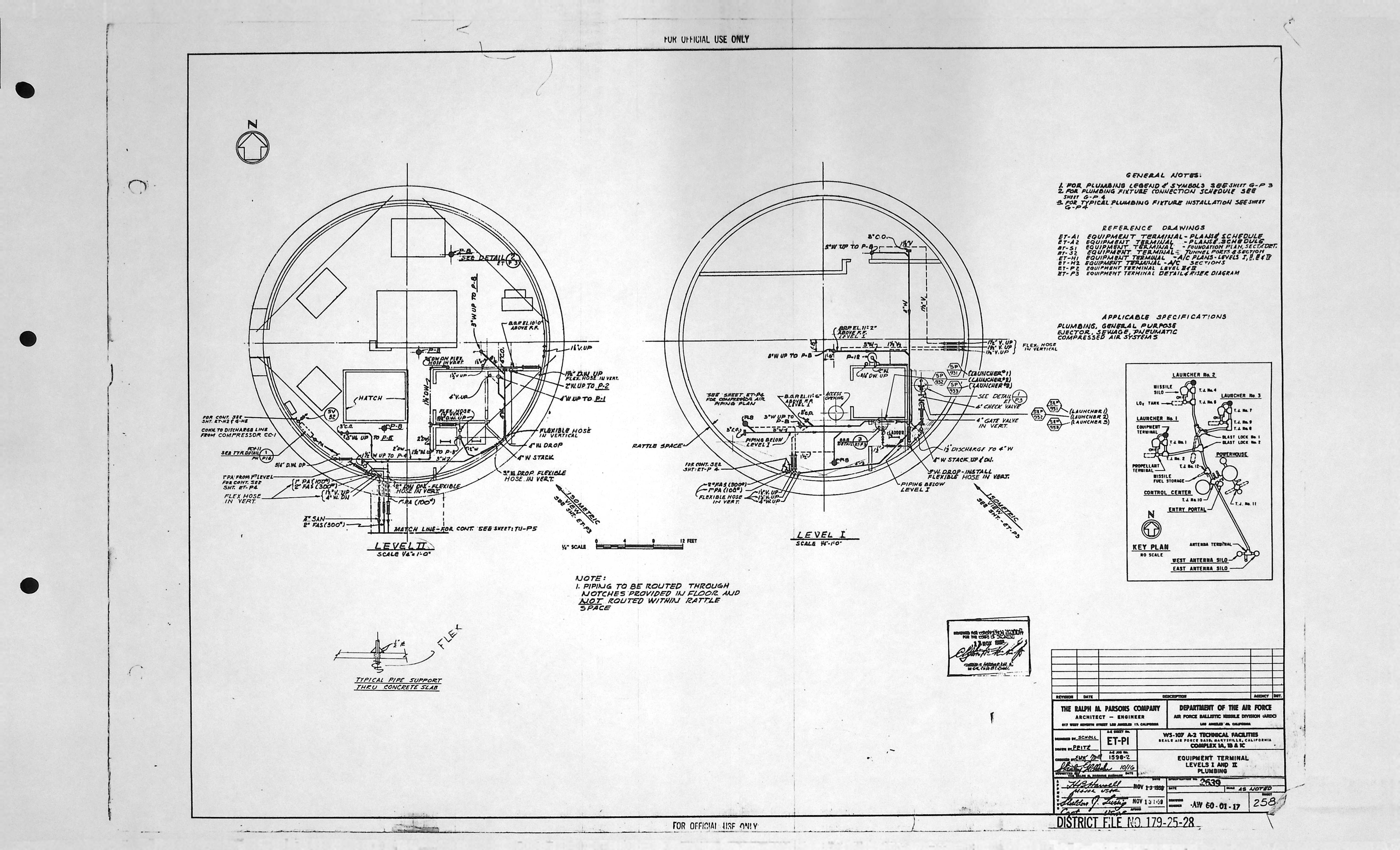
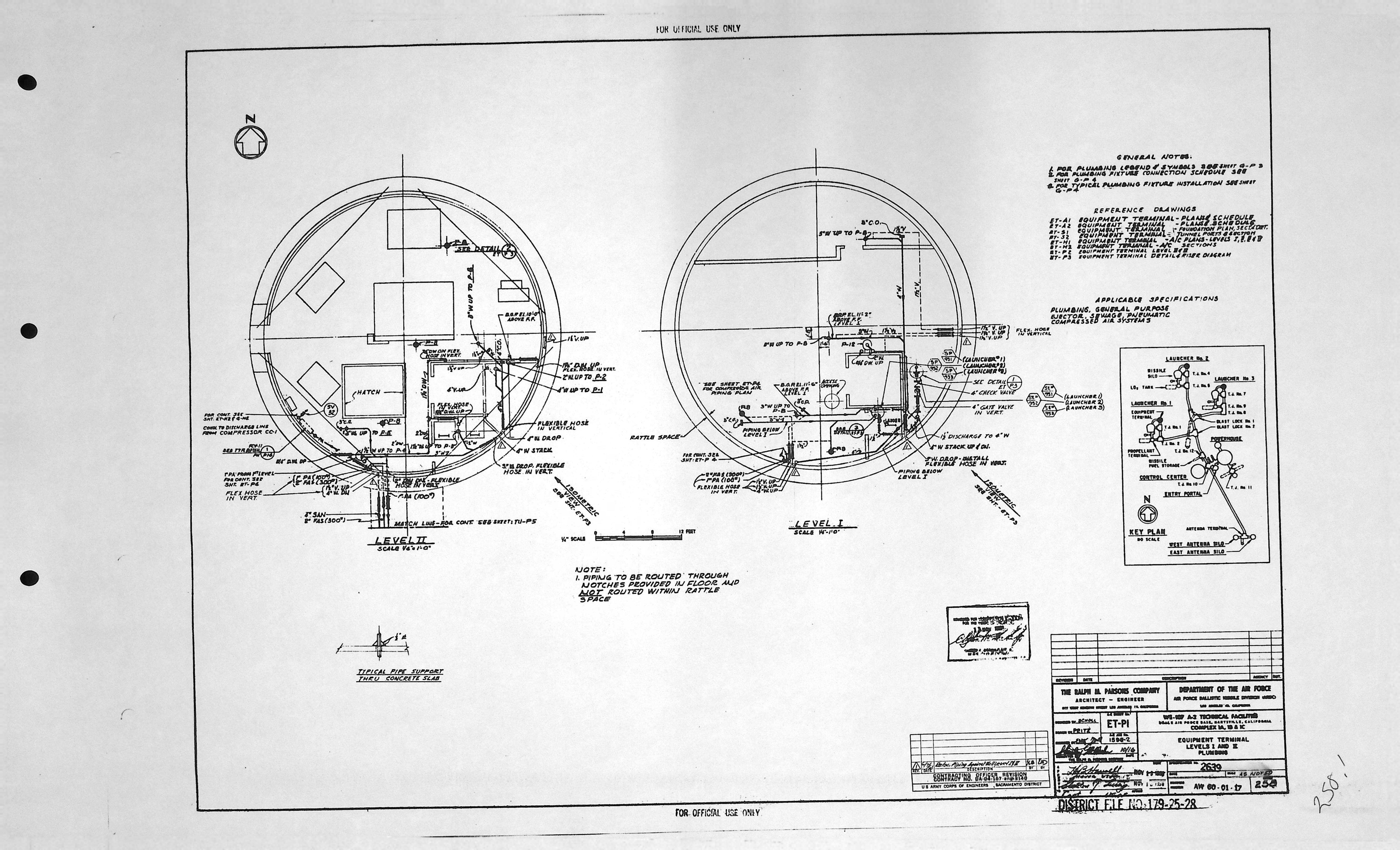
Equipment Terminal - Plumbing/Piping drawings (9)
| Drawing Number | Description |
|---|---|
| ET-P1 | LEVELS I AND II PLUMBING |
| ET-P1 | LEVELS I AND II PLUMBING * |
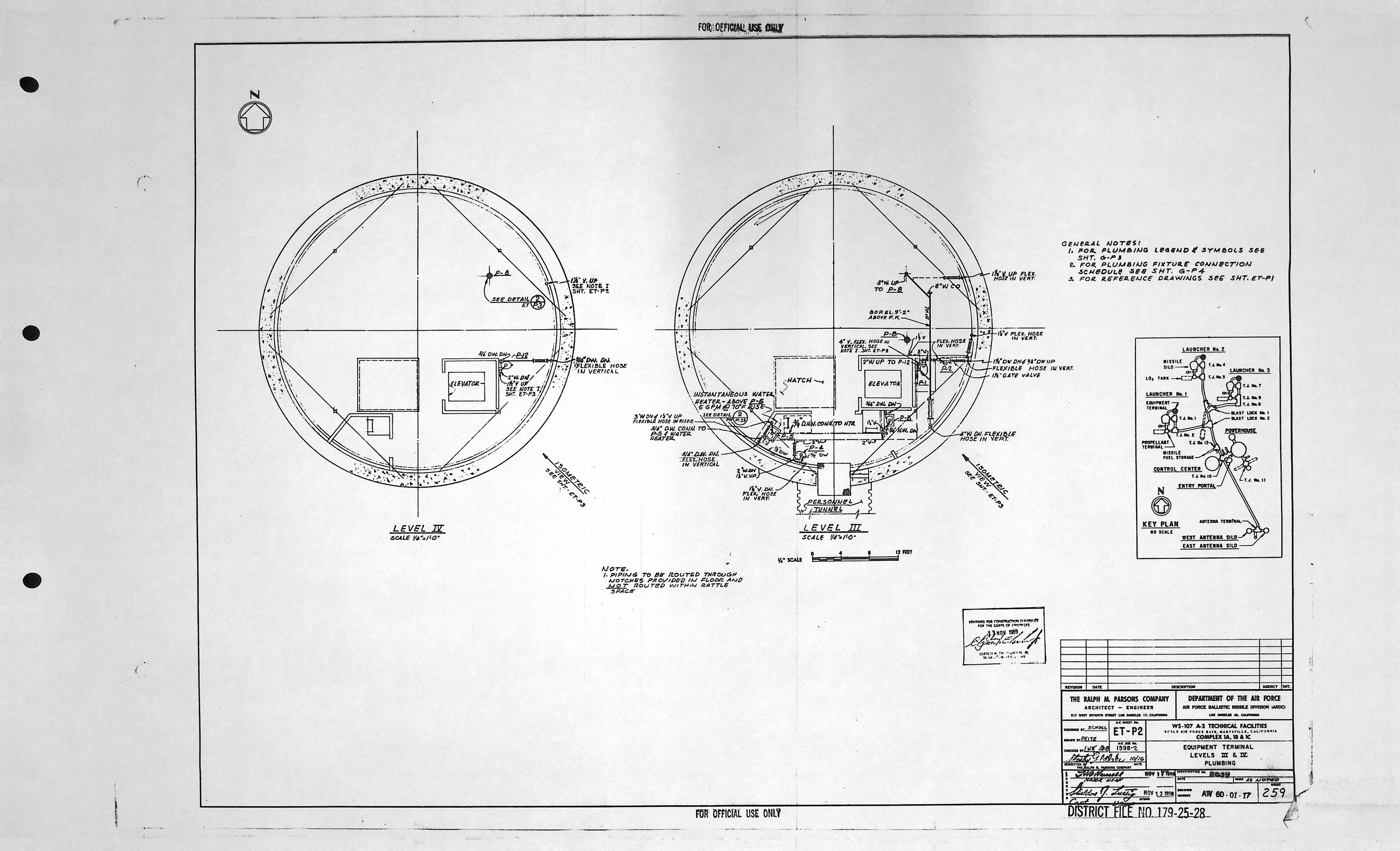
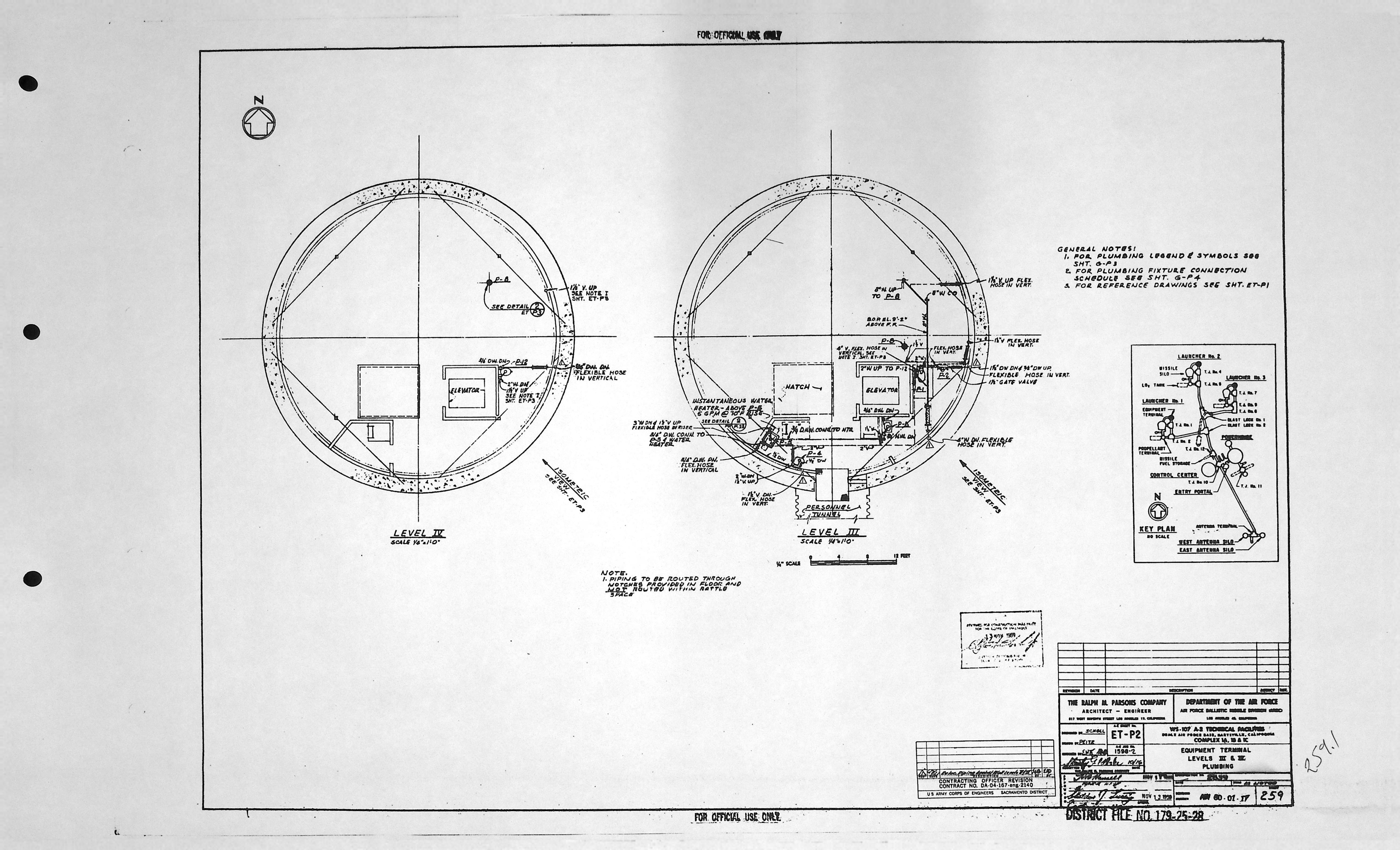
| ET-P2 | LEVELS III AND IV PLUMBING |
| ET-P2 | LEVELS III AND IV PLUMBING * |
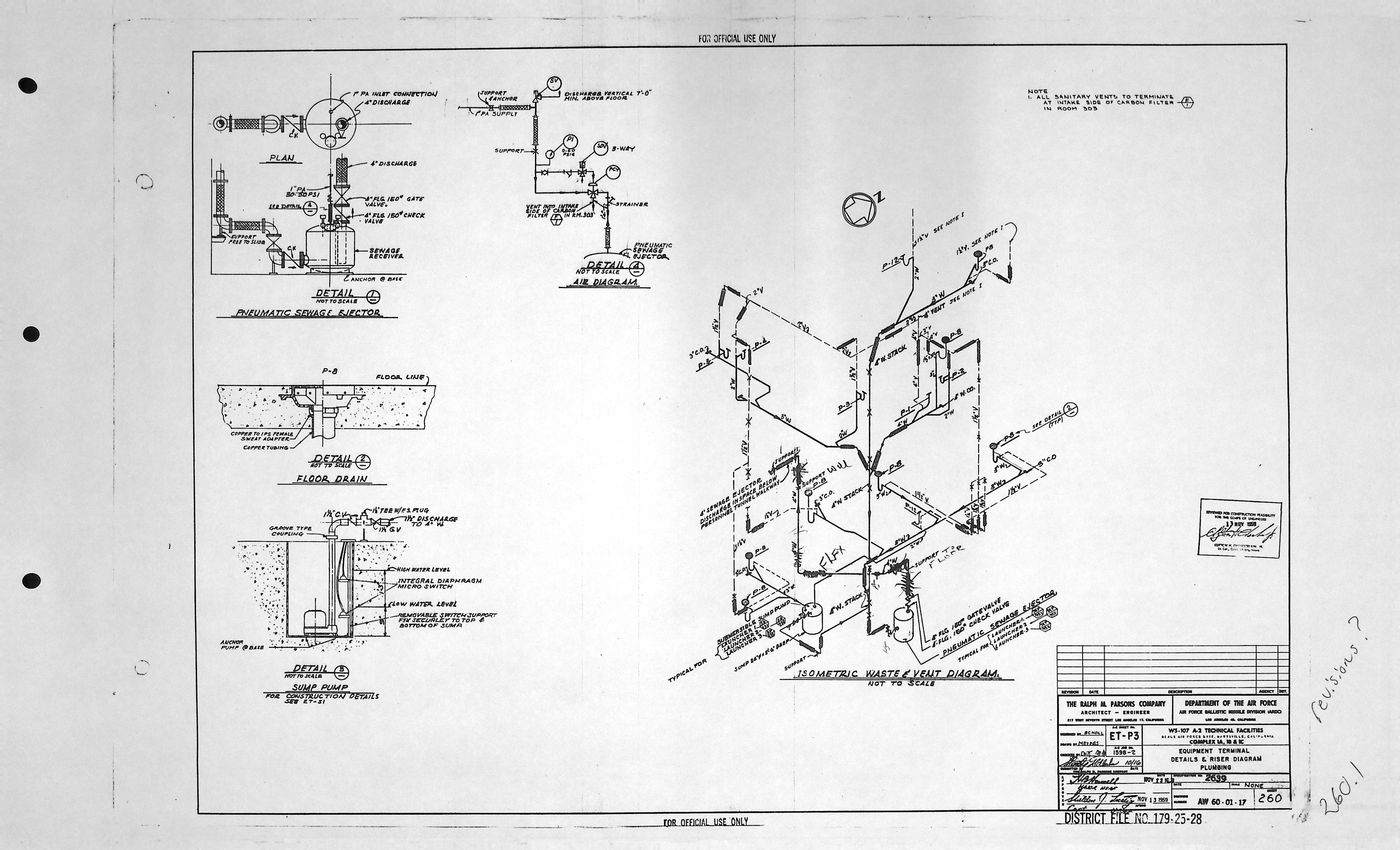
| ET-P3 | DETAILS & RISER DIAGRAM PLUMBING |
| ET-P3 | DETAILS & RISER DIAGRAM PLUMBING * |
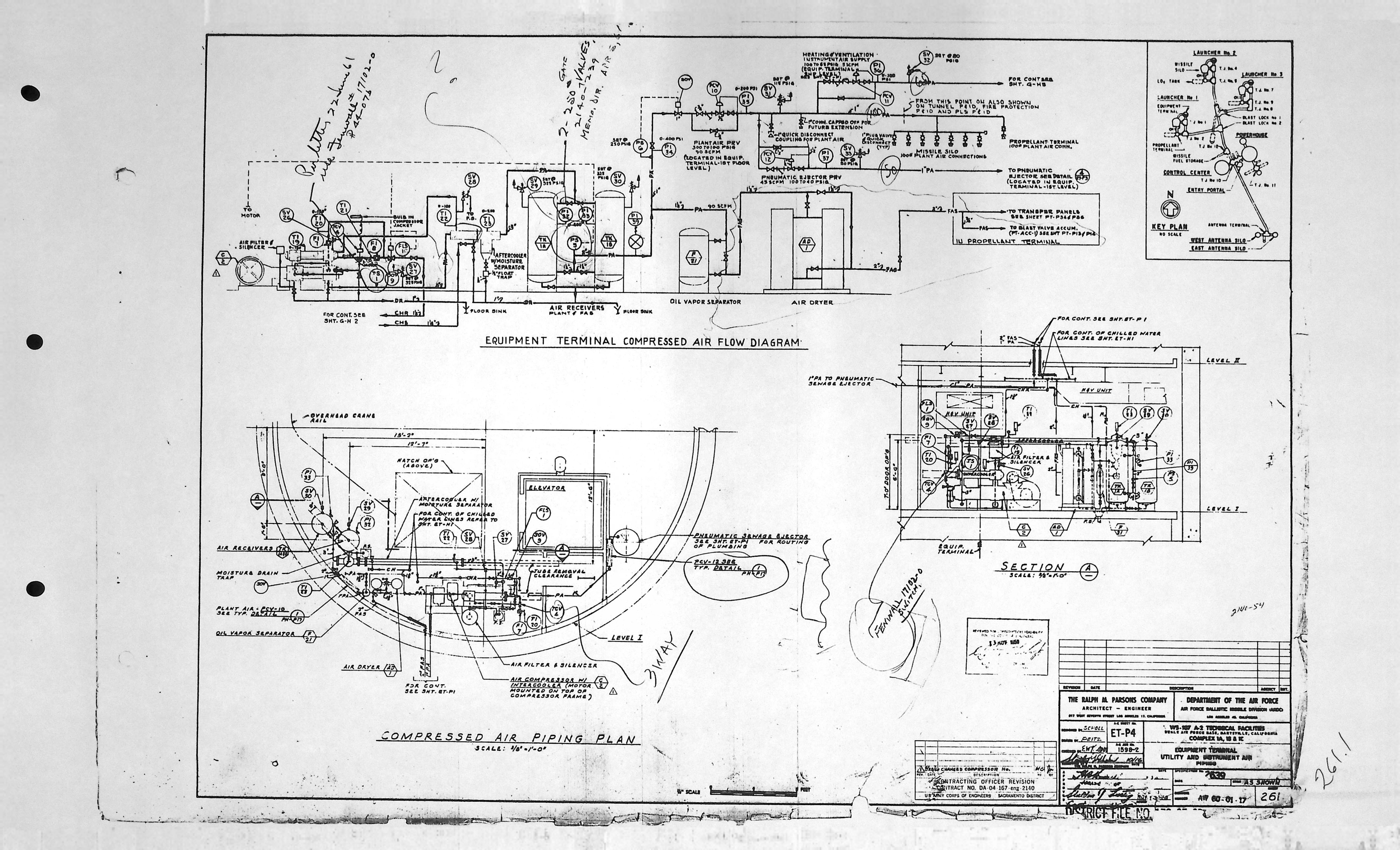
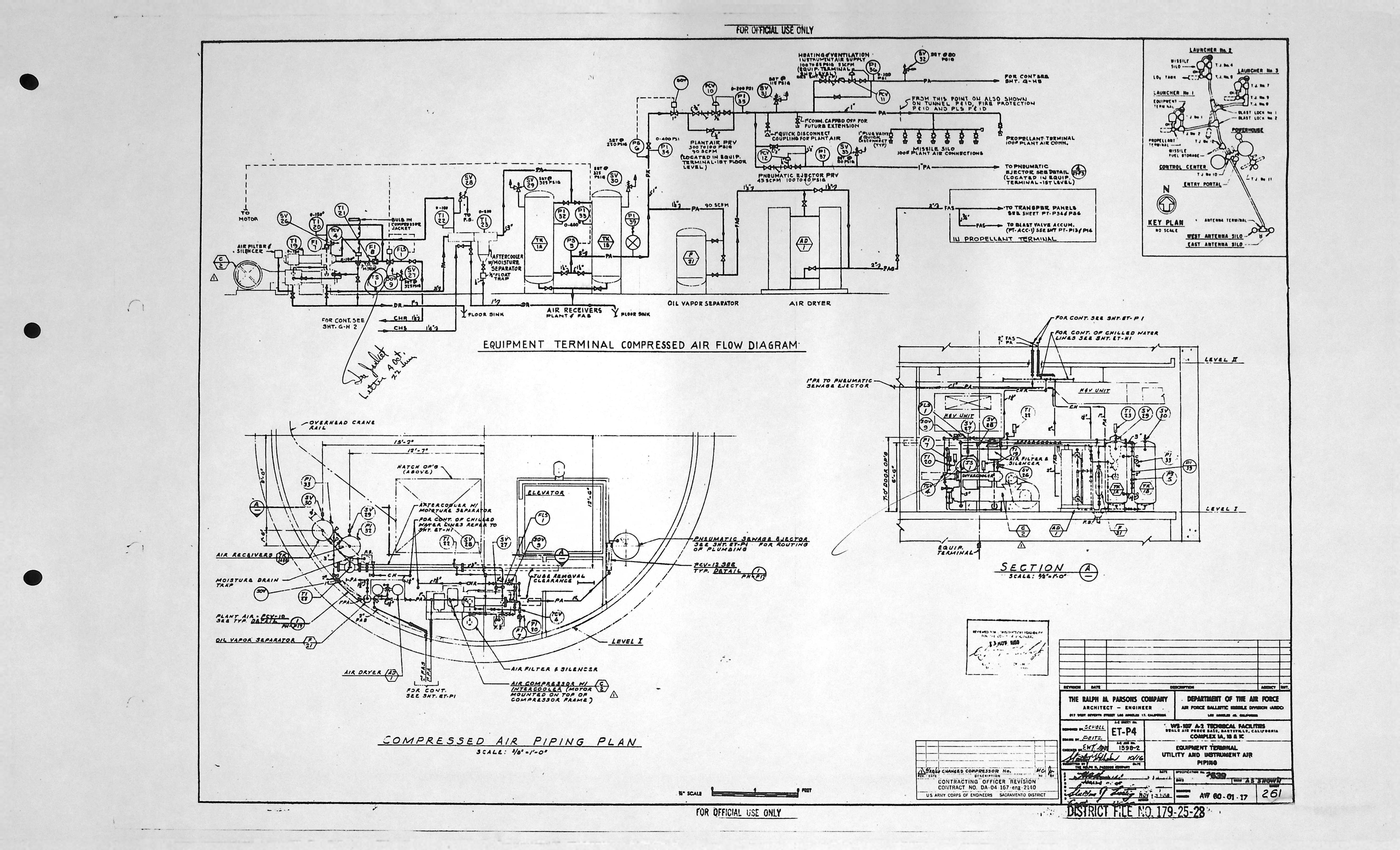
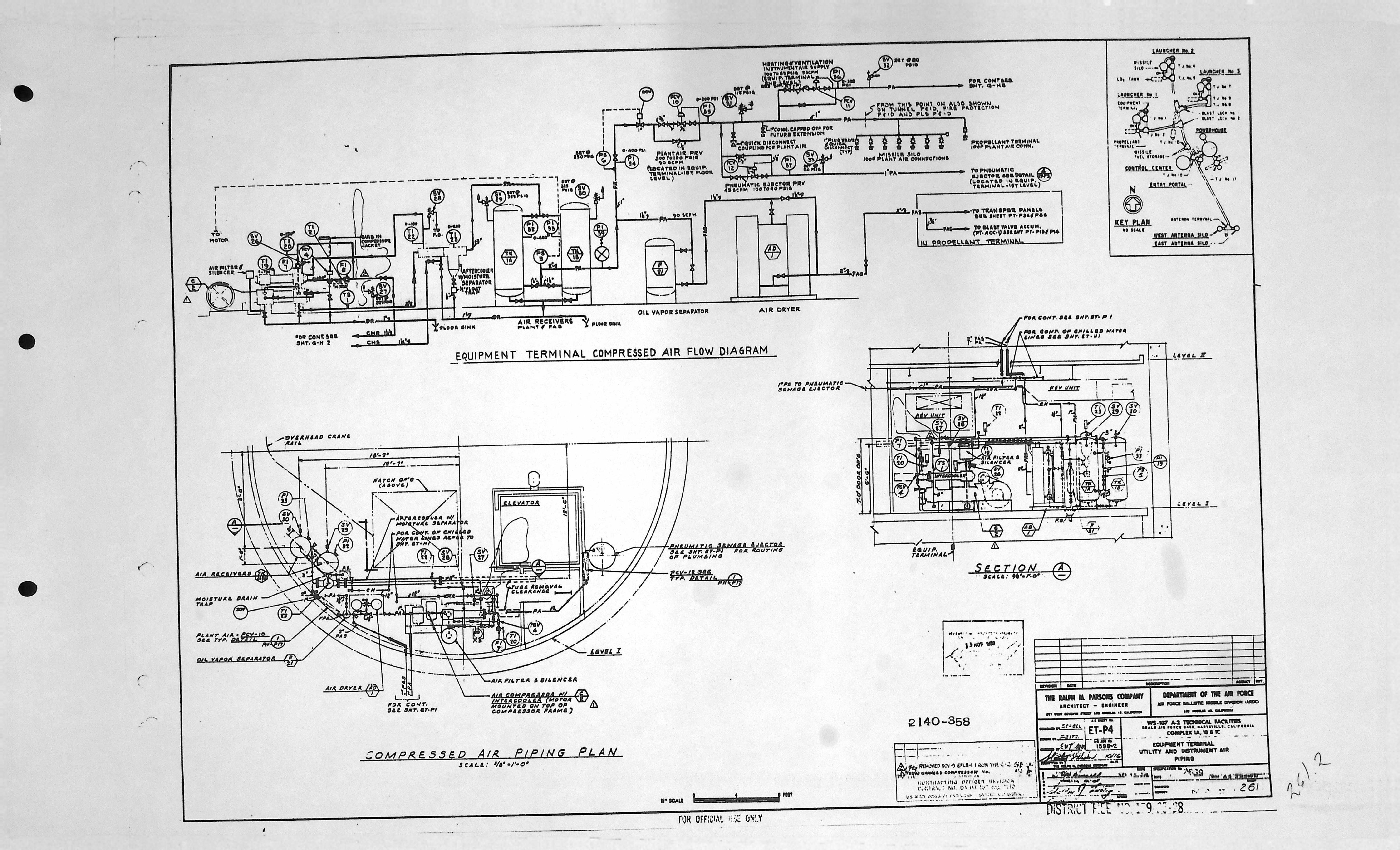
| ET-P4 | UTILITY AND INSTRUMENT AIR PIPING |
| ET-P4 | UTILITY AND INSTRUMENT AIR PIPING * |
| ET-P4 | UTILITY AND INSTRUMENT AIR PIPING * |
Equipment Terminal - Structural drawings (10)
| Drawing Number | Description |
|---|---|
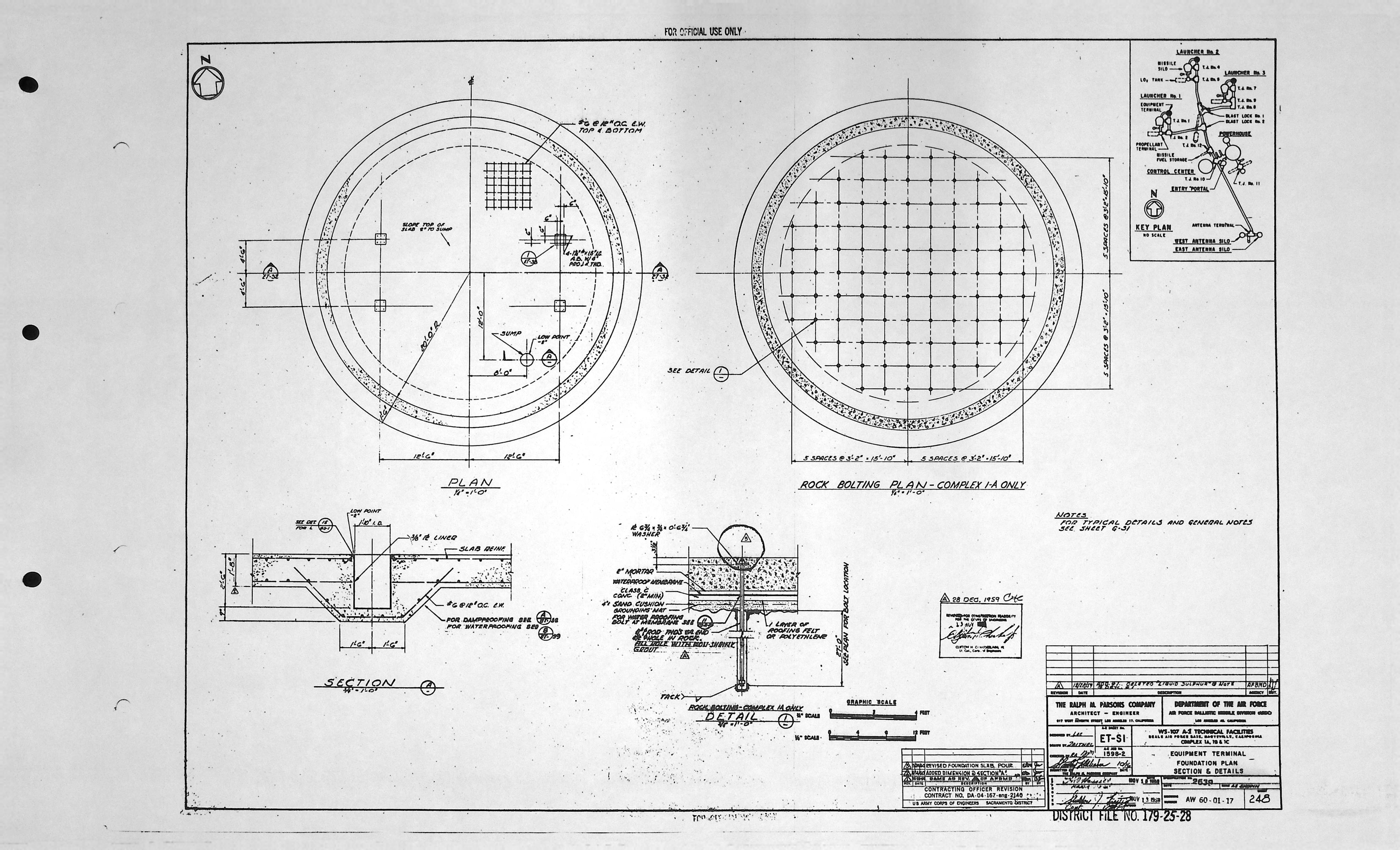
| ET-S1 | FOUNDATION PLAN SECTION & DETAILS |
| ET-S2 | TUNNEL PORTS ELEVATIONS & SECTION |
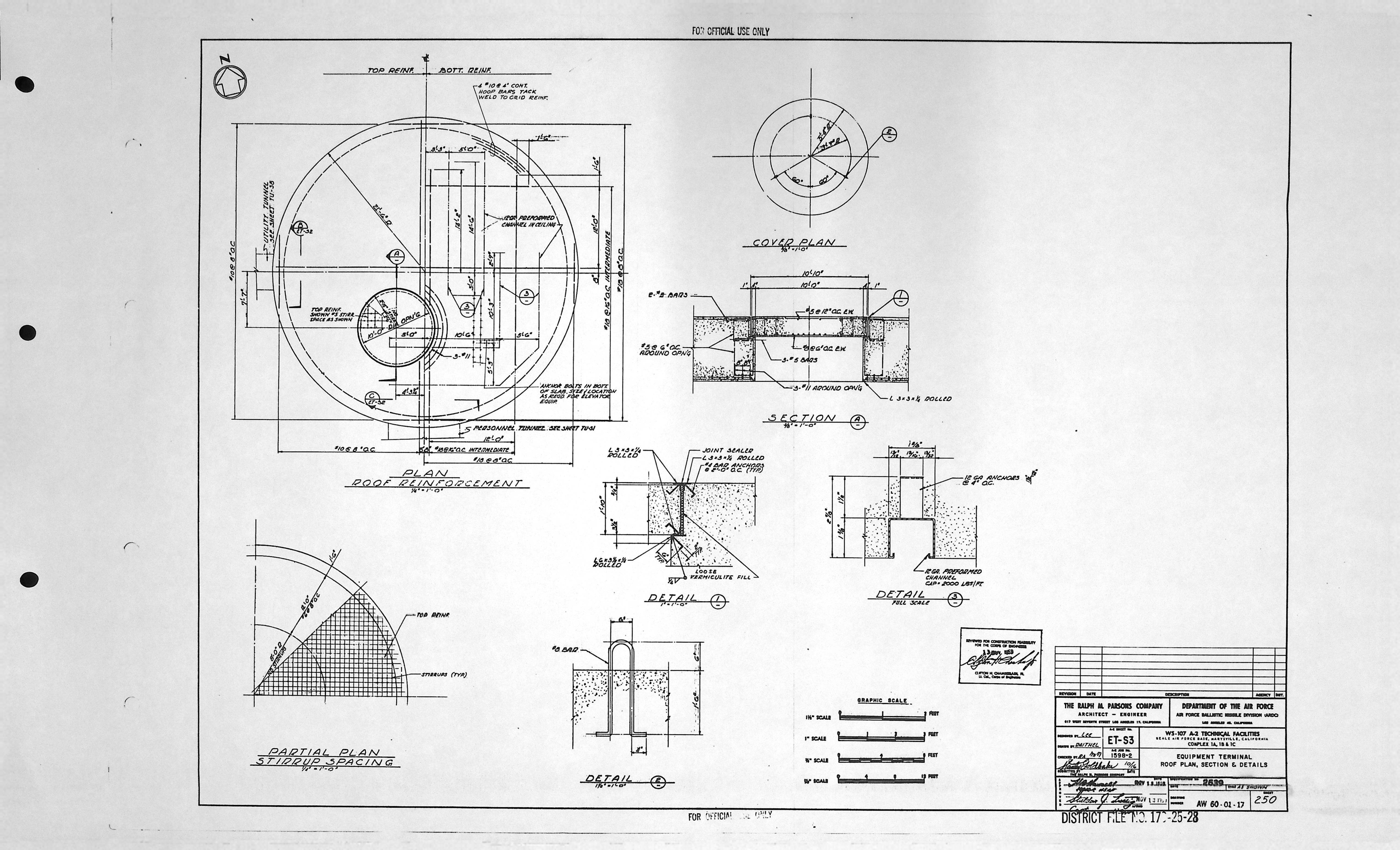
| ET-S3 | ROOF PLAN, SECTION & DETAILS |
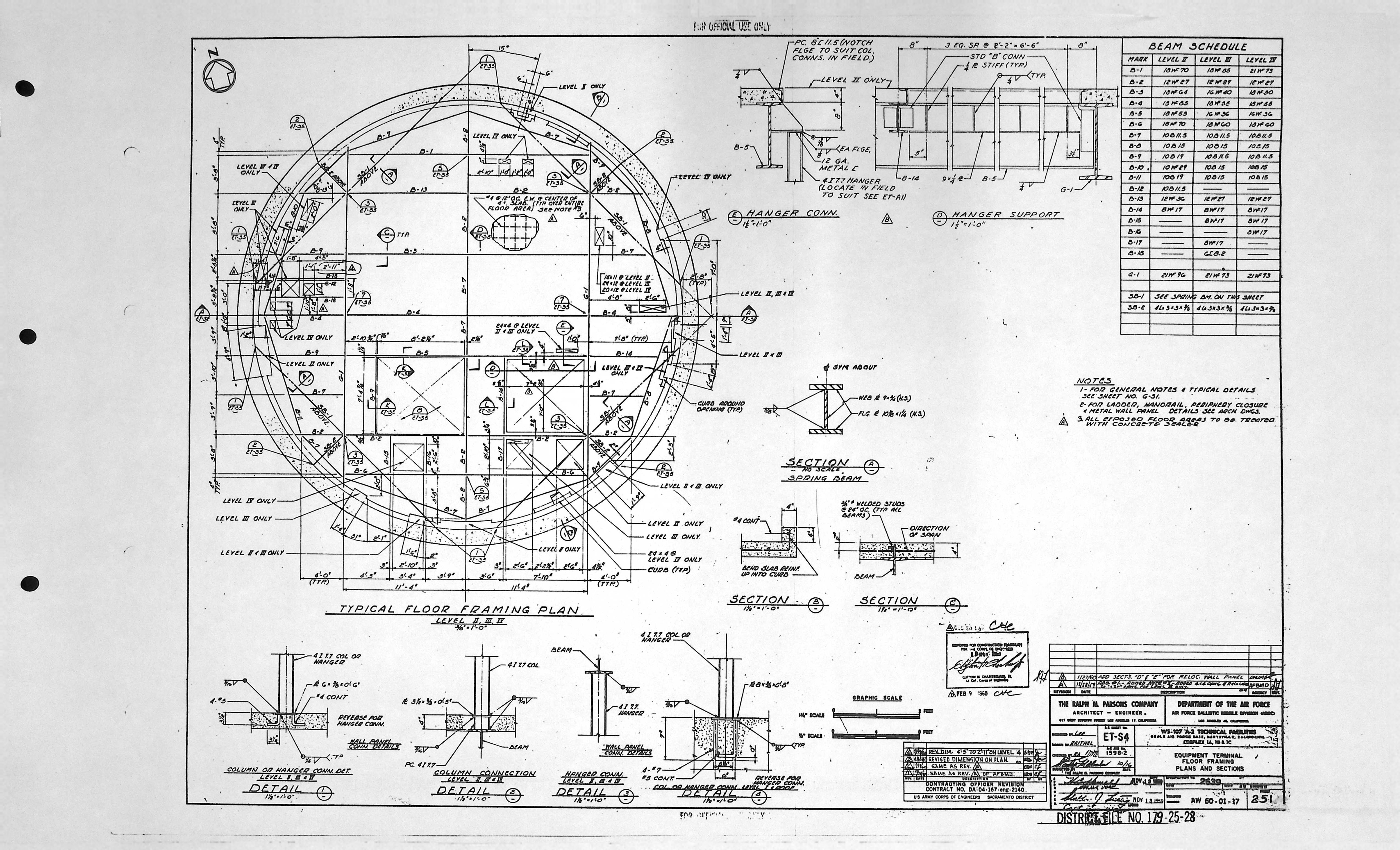
| ET-S4 | FLOOR FRAMING PLANS AND SECTIONS |
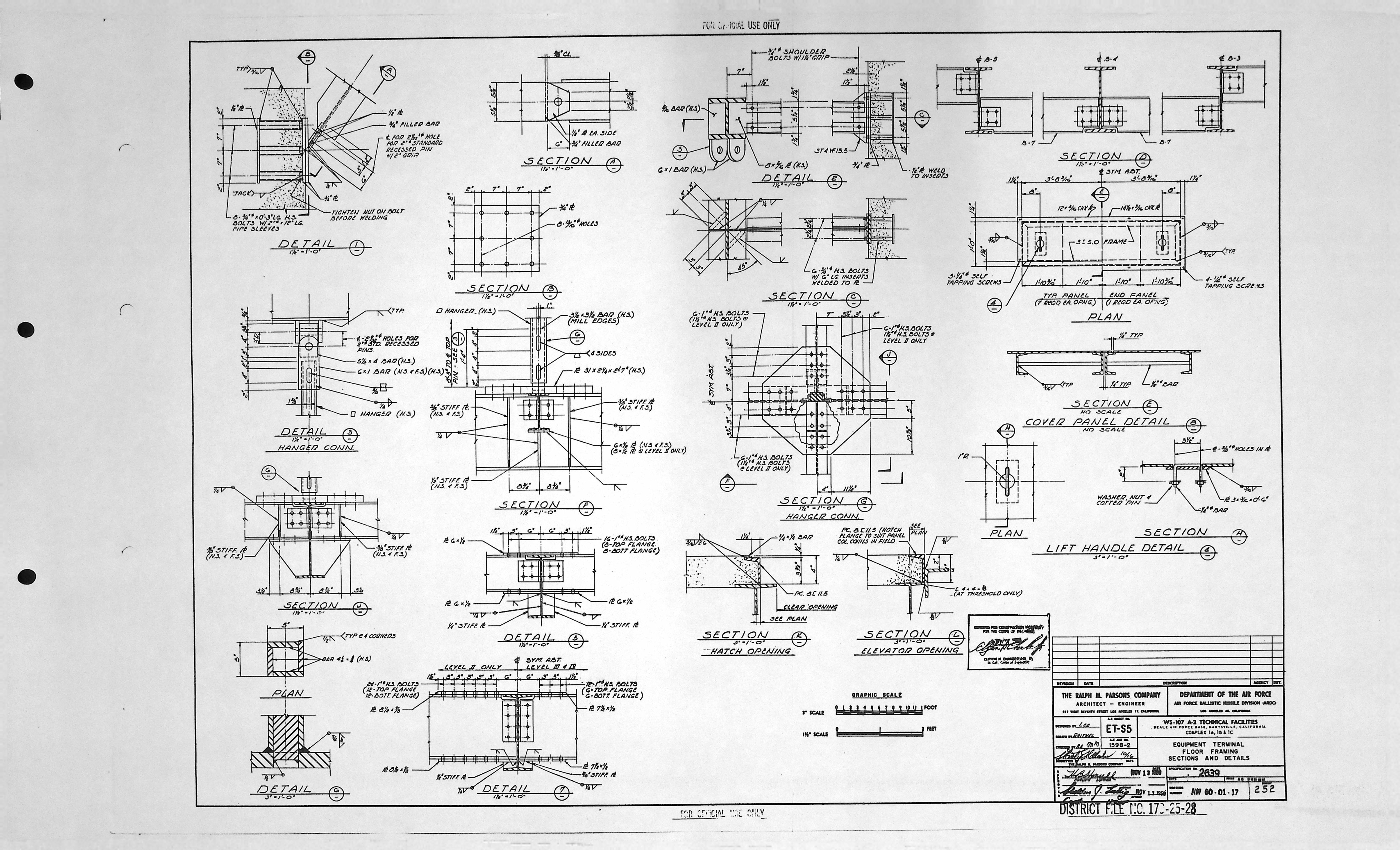
| ET-S5 | FLOOR FRAMING SECTIONS AND DETAILS |
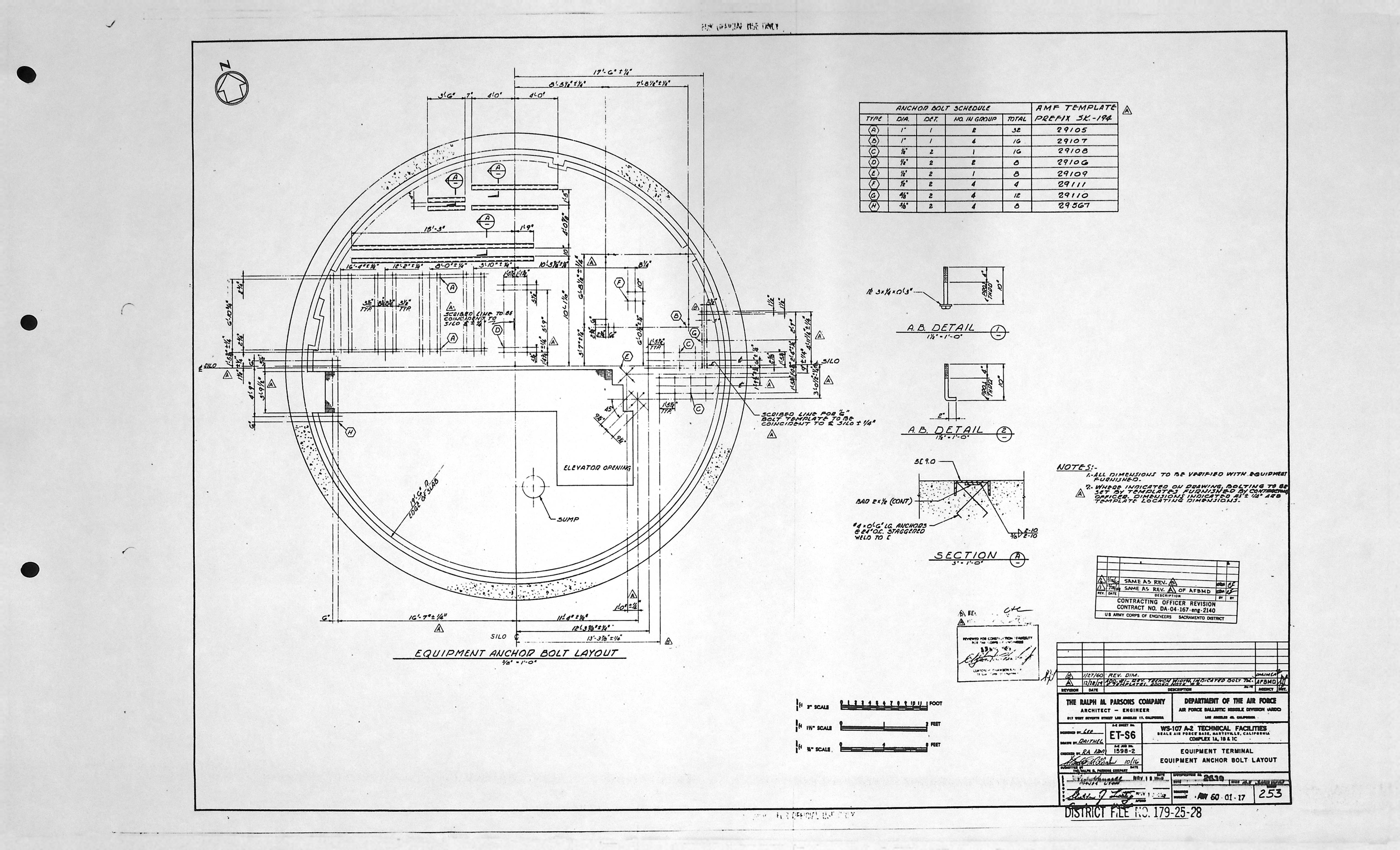
| ET-S6 | EQUIPMENT ANCHOR BOLT LAYOUT |
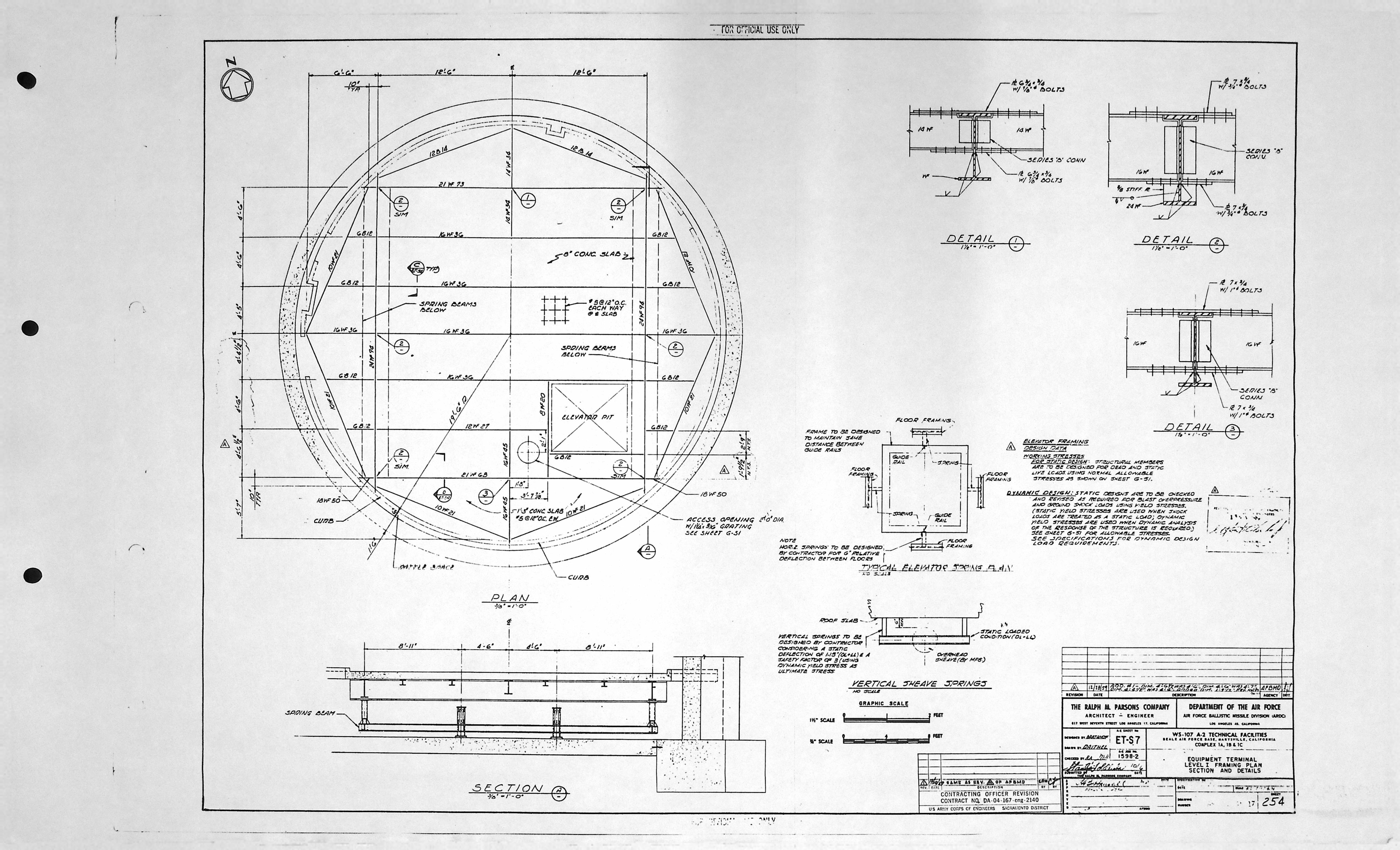
| ET-S7 | LEVEL I FRAMING PLAN SECTION AND DETAILS |
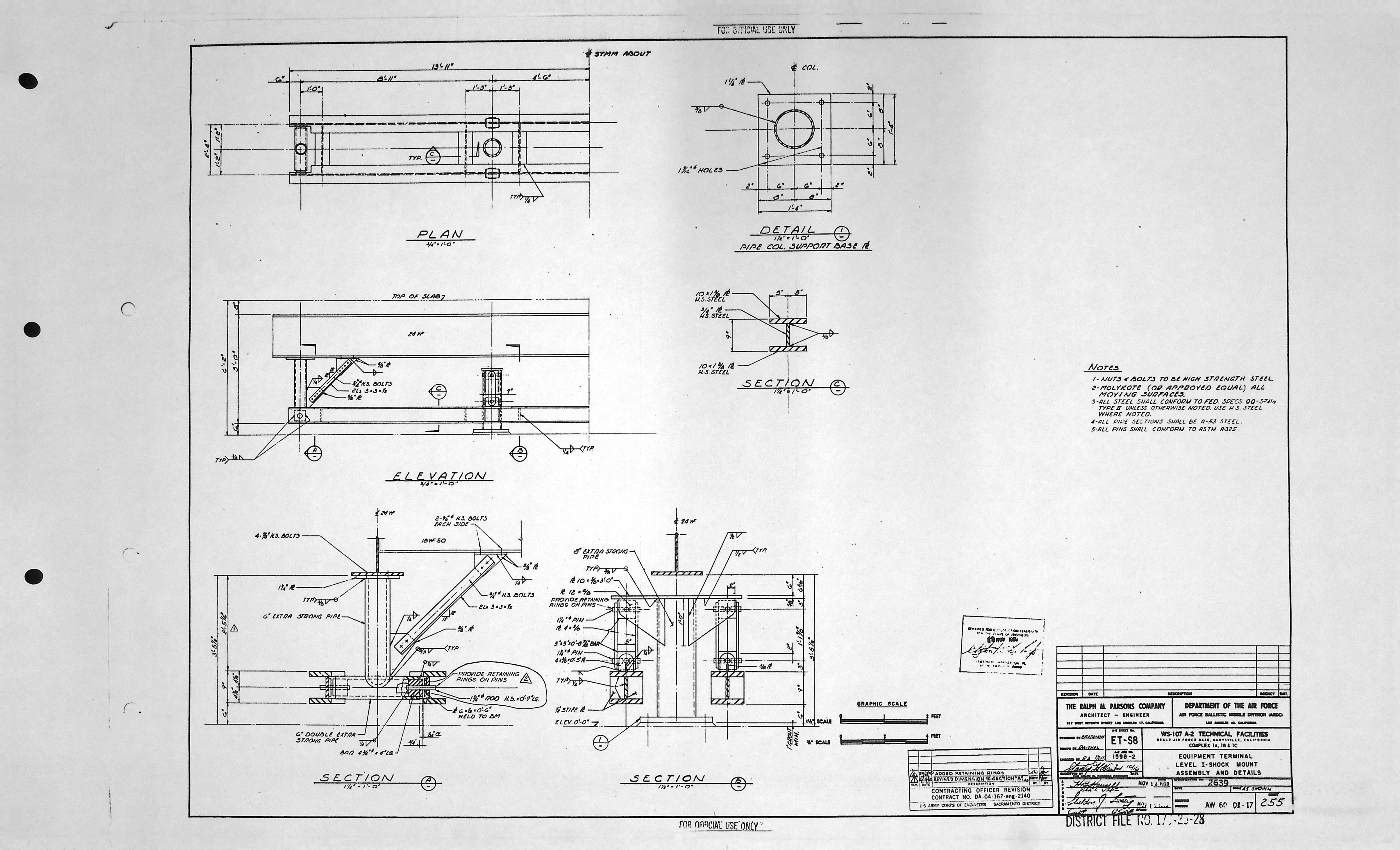
| ET-S8 | LEVEL I - SHOCK MOUNT ASSEMBLY AND DETAILS |
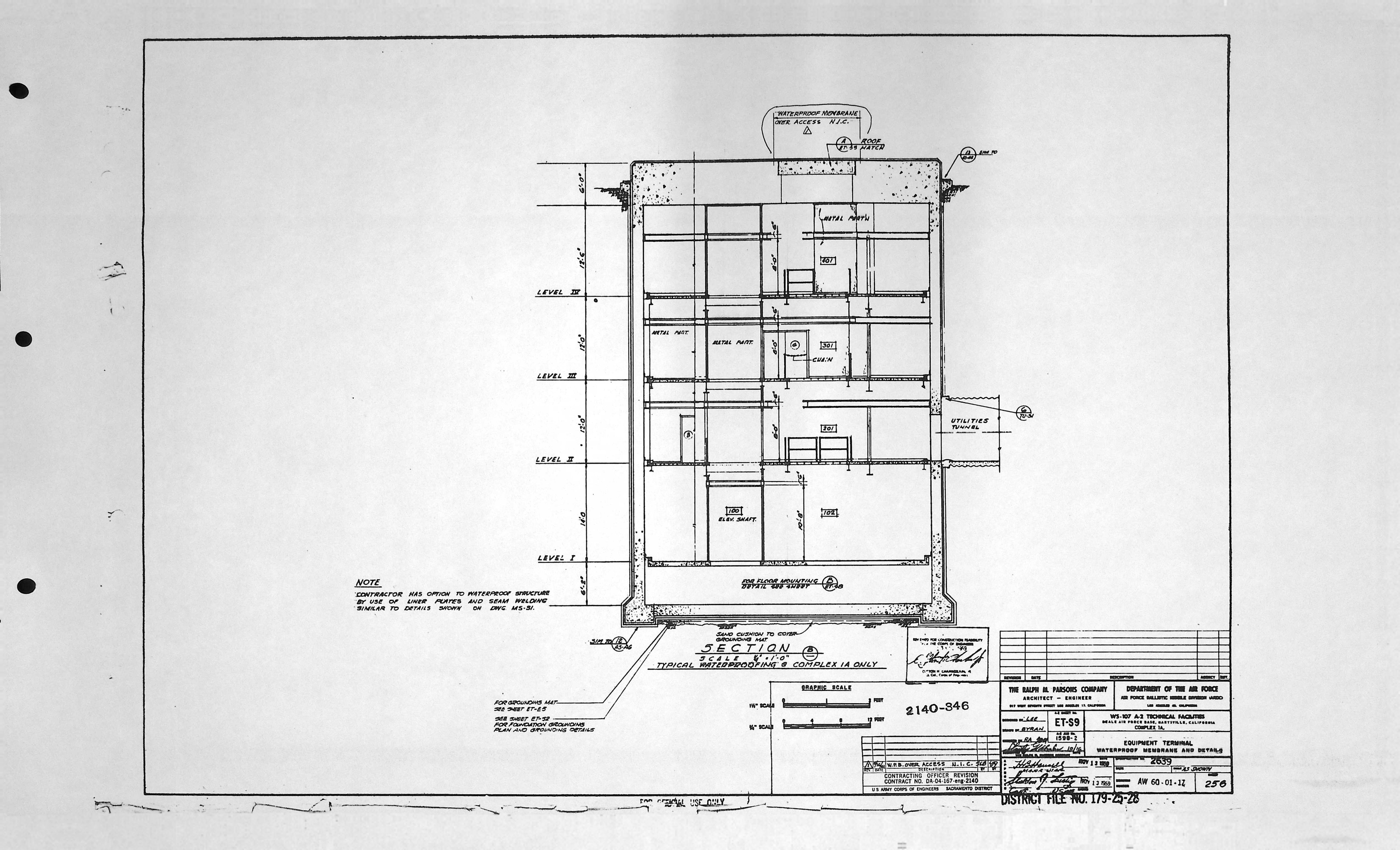
| ET-S9 | WATERPROOF MEMBRANE AND DETAILS |
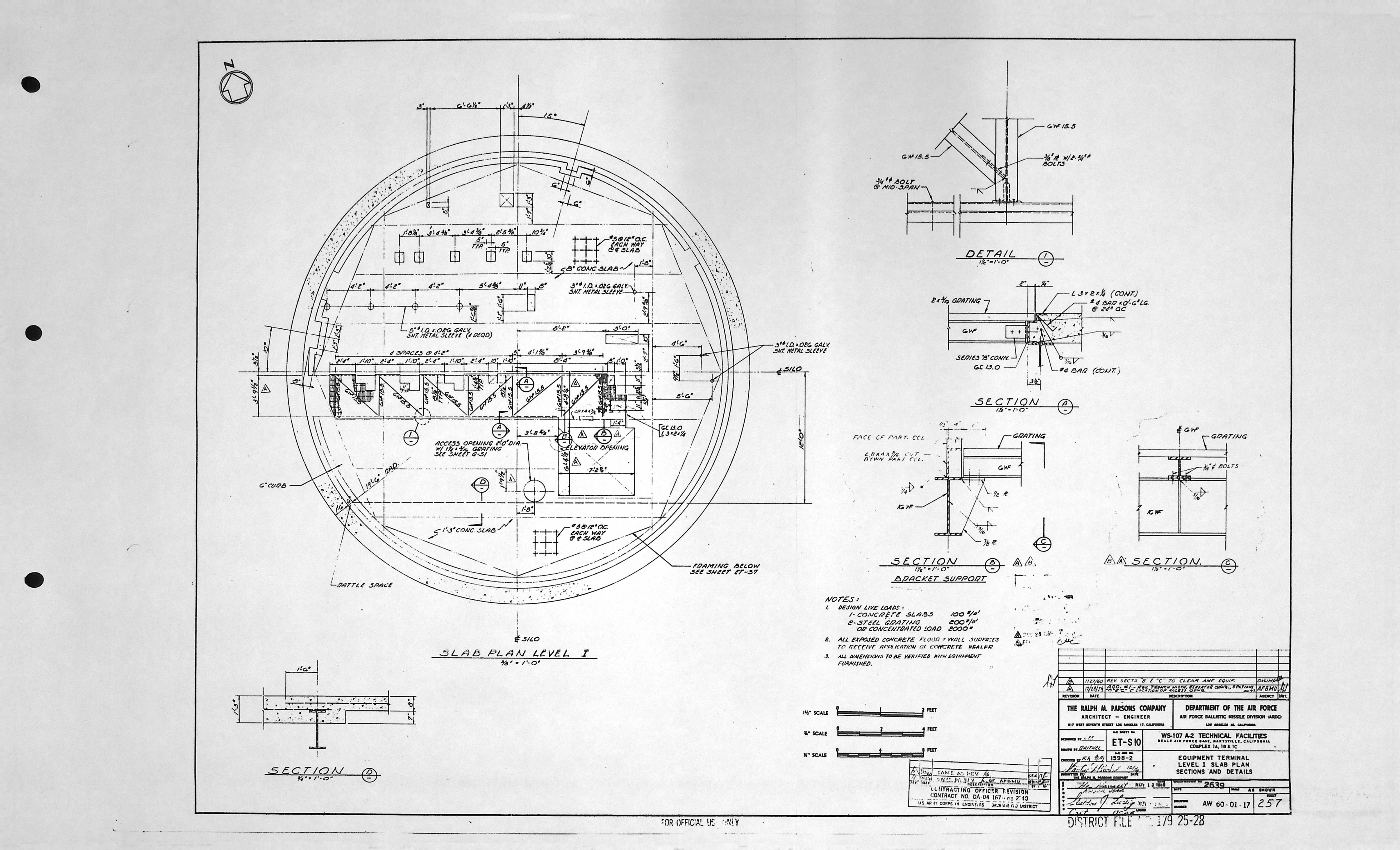
| ET-S10 | LEVEL I SLAB PLAN SECTIONS & DETAILS |