Antenna Silo - Architectural drawings (7)
| Drawing Number | Description |
|---|---|
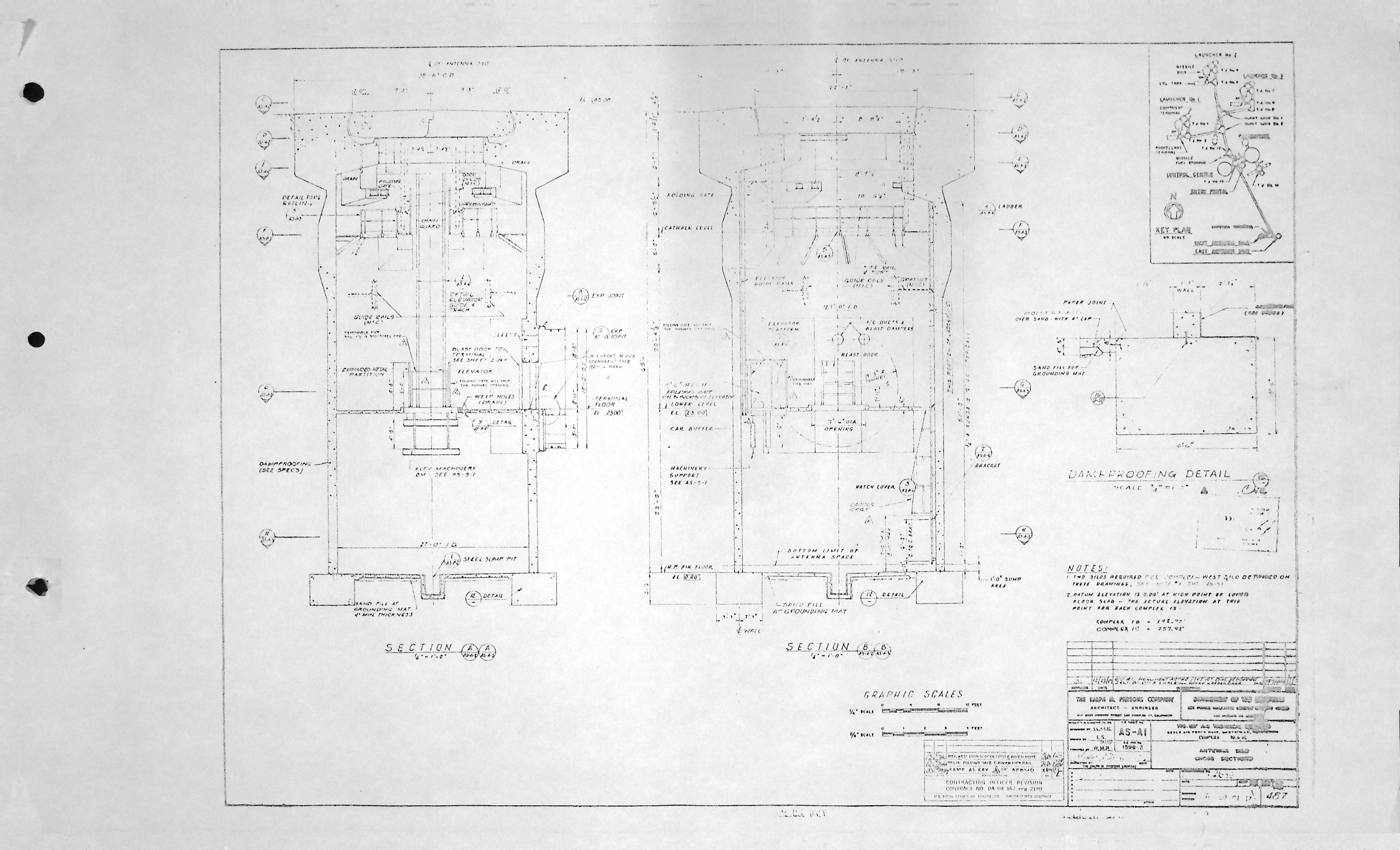
| AS-A1 | CROSS SECTION |
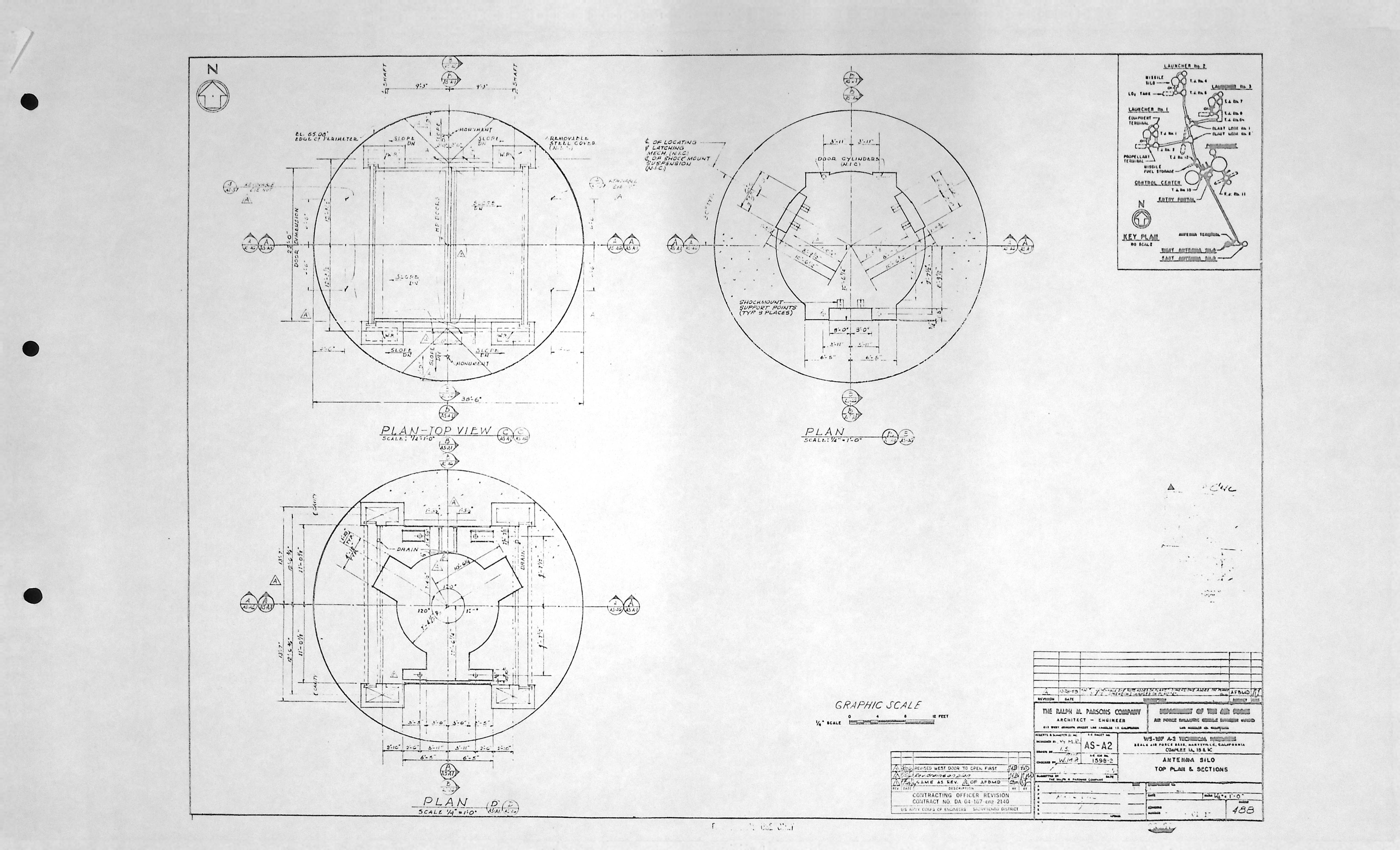
| AS-A2 | TOP PLAN & SECTIONS |
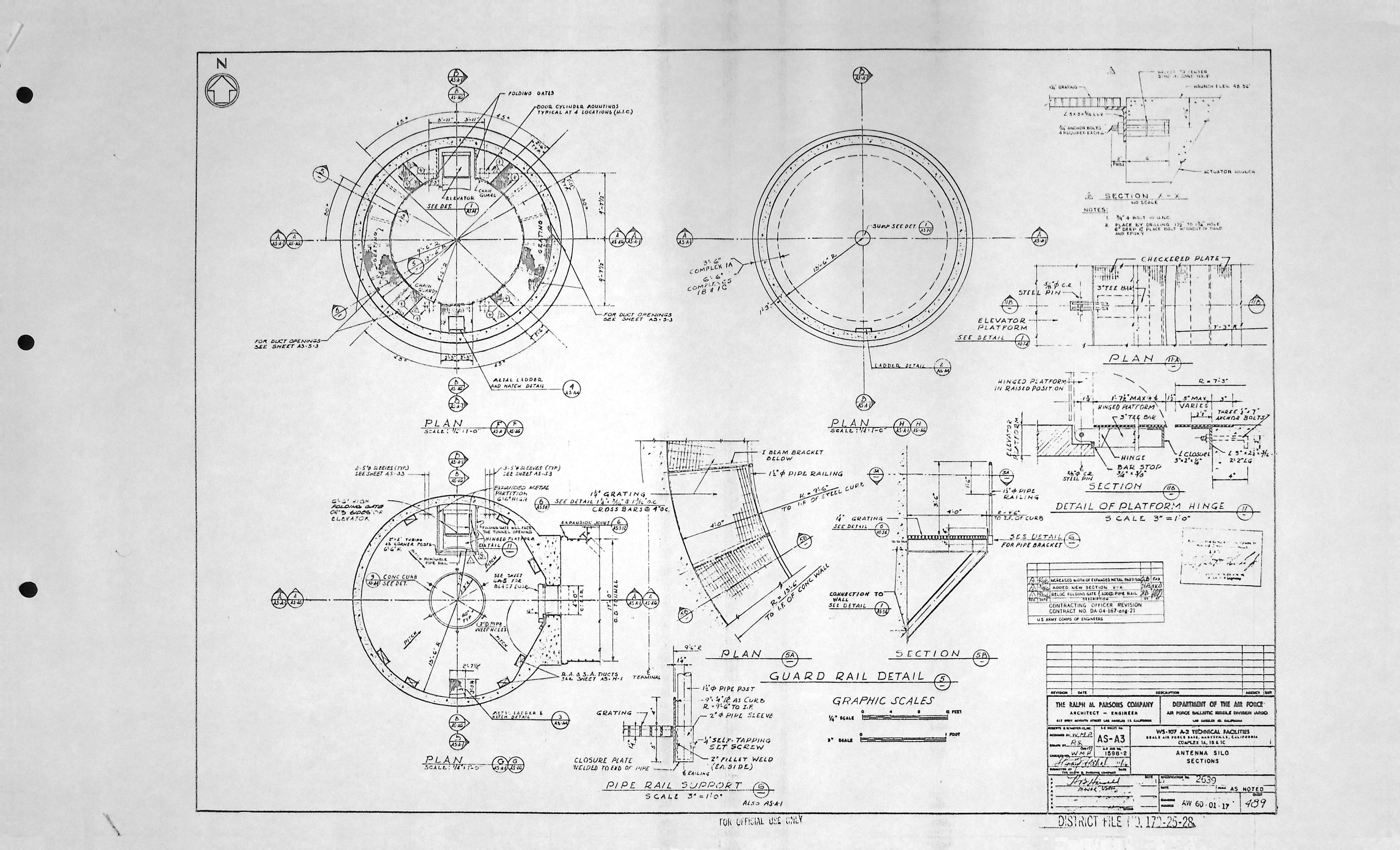
| AS-A3 | SECTIONS |
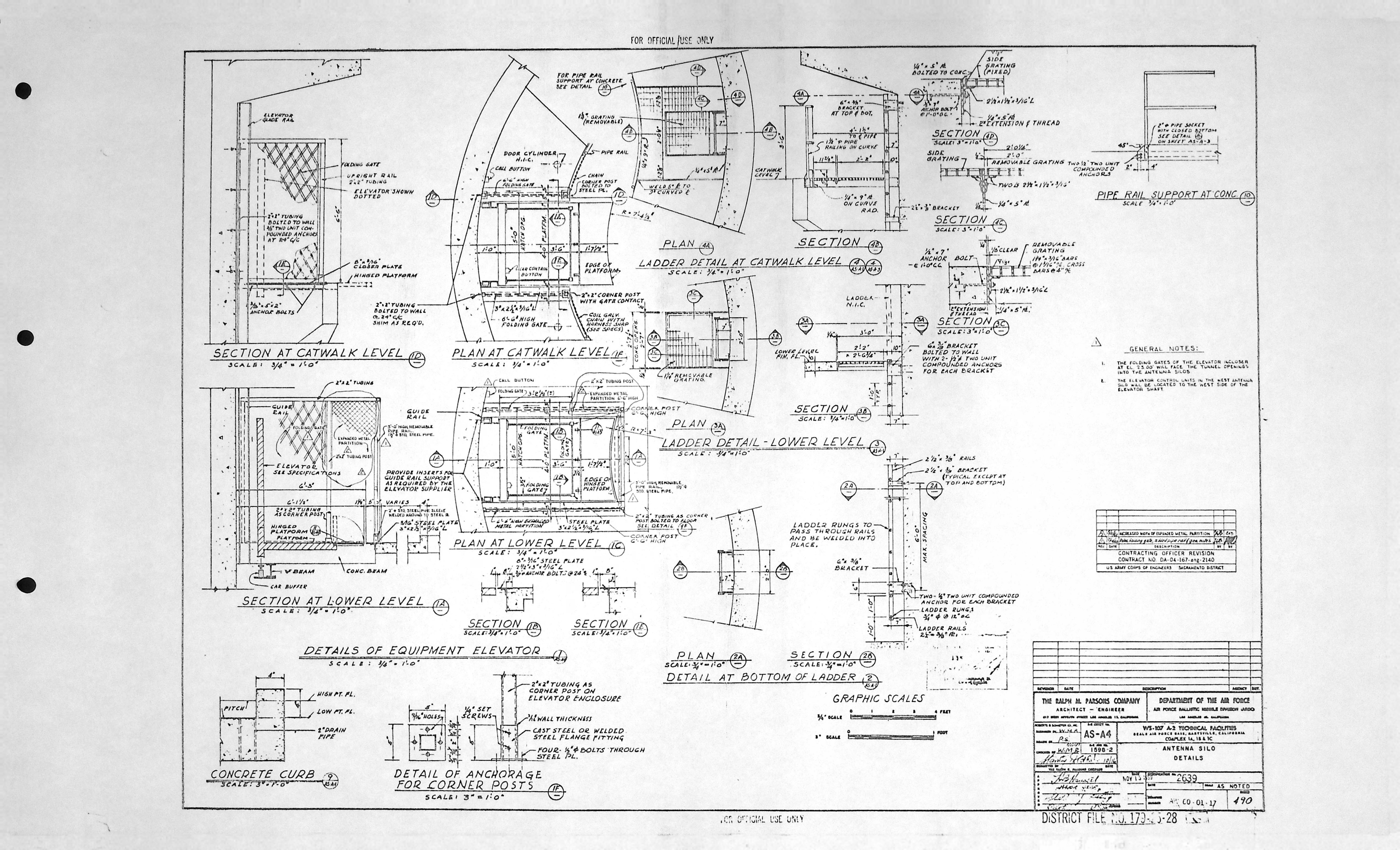
| AS-A4 | DETAILS |
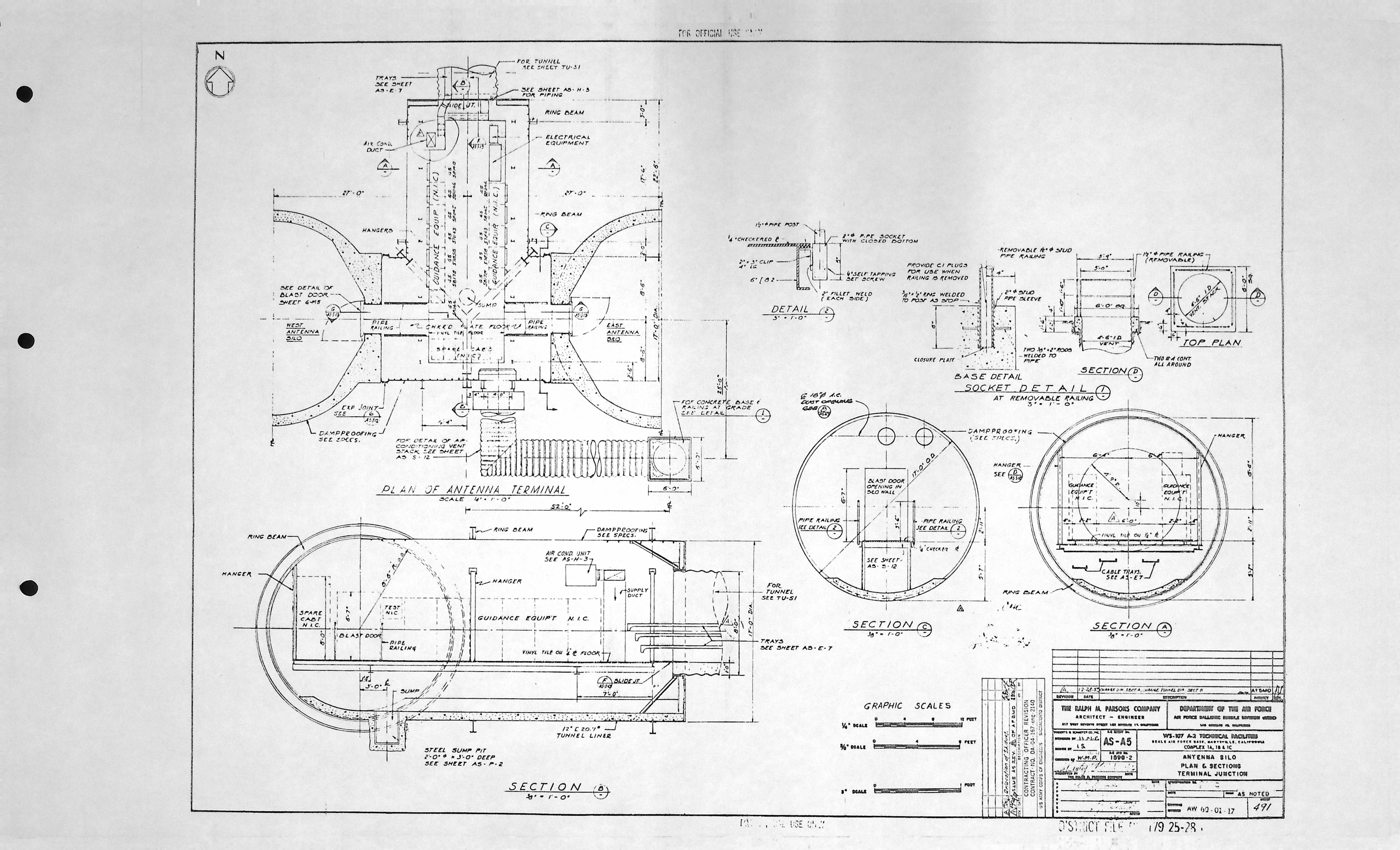
| AS-A5 | PLAN & SECTIONS TERMINAL JUNCTION |
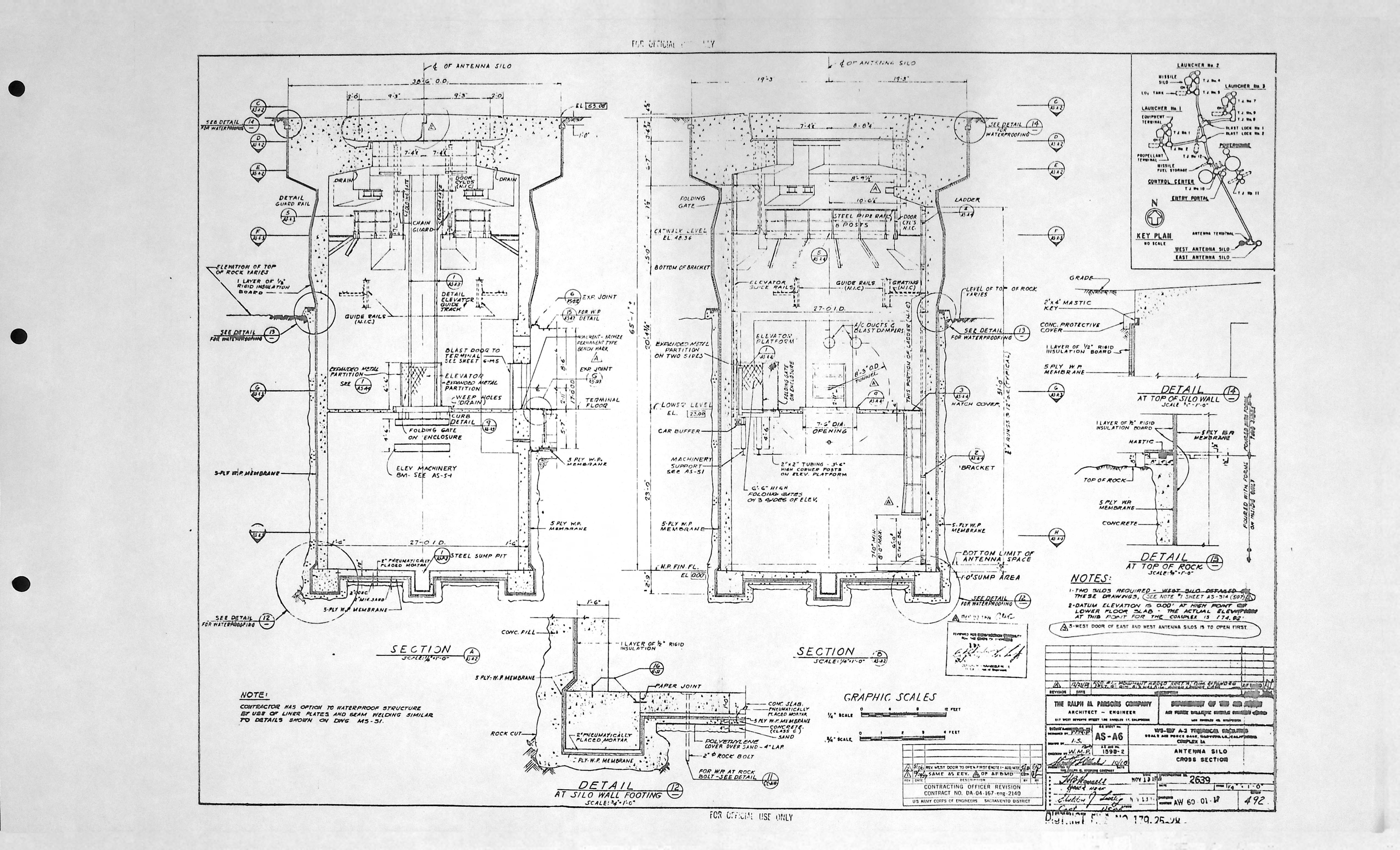
| AS-A6 | TOP PLAN & SECTIONS |
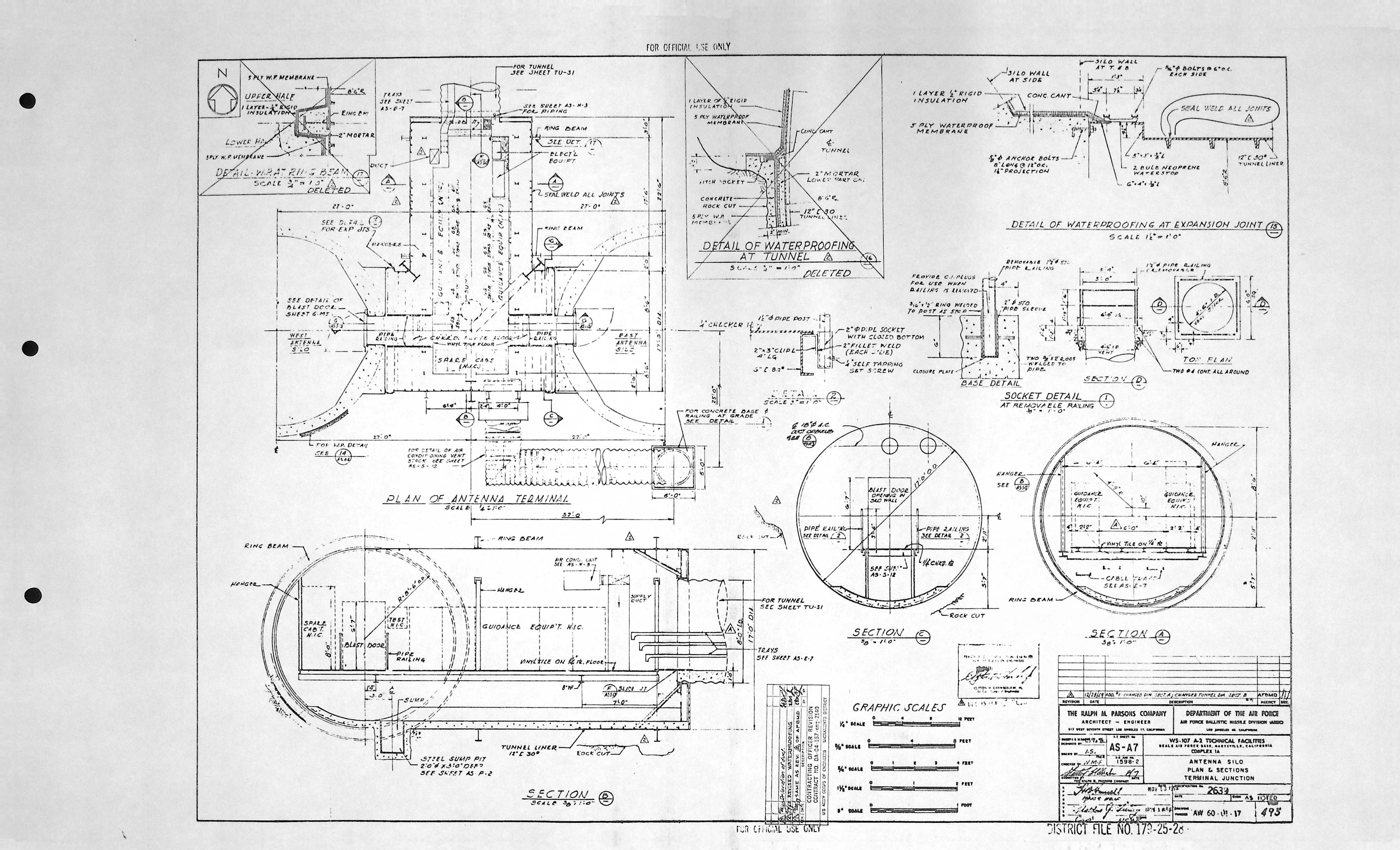
| AS-A7 | SECTIONS |
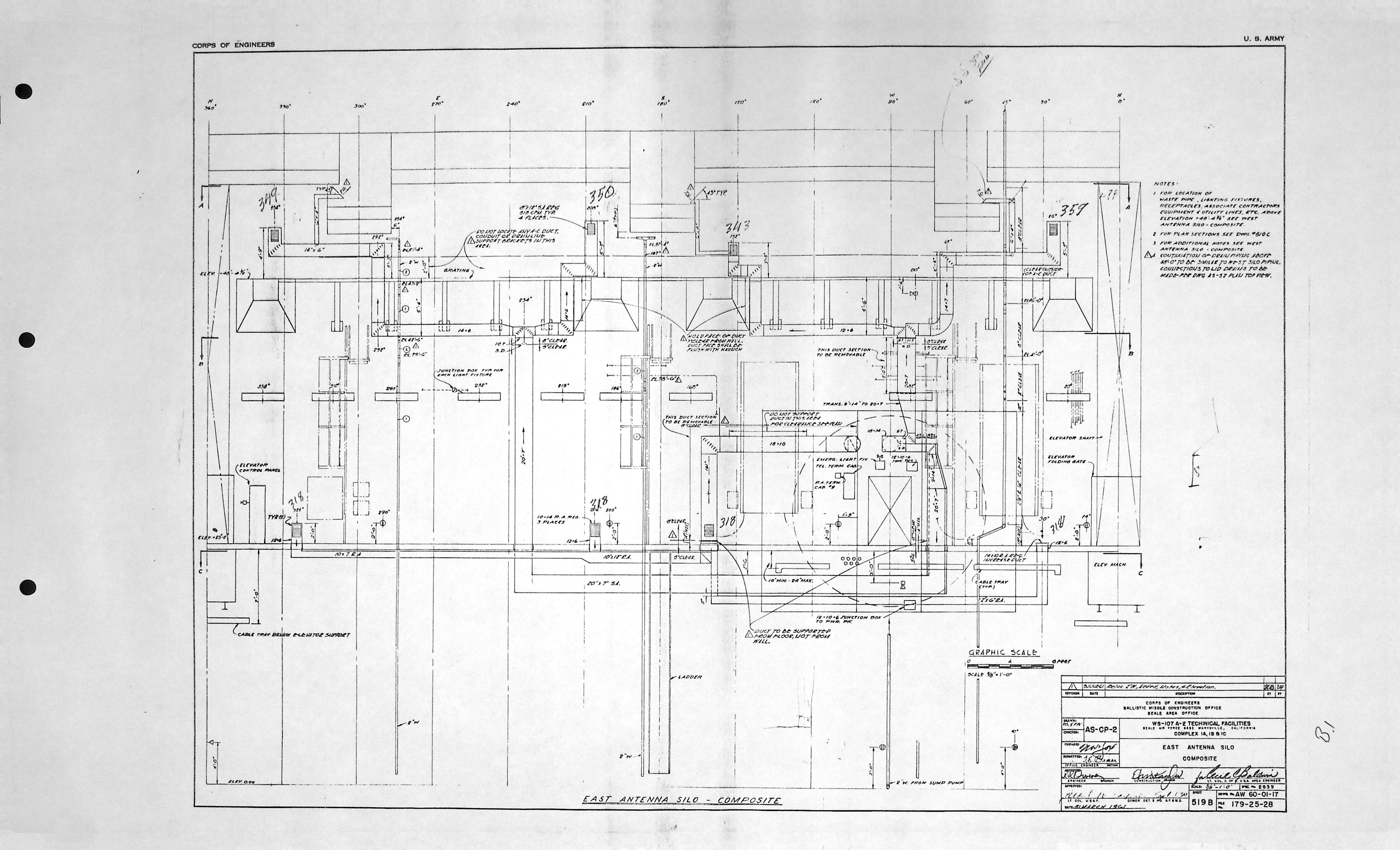
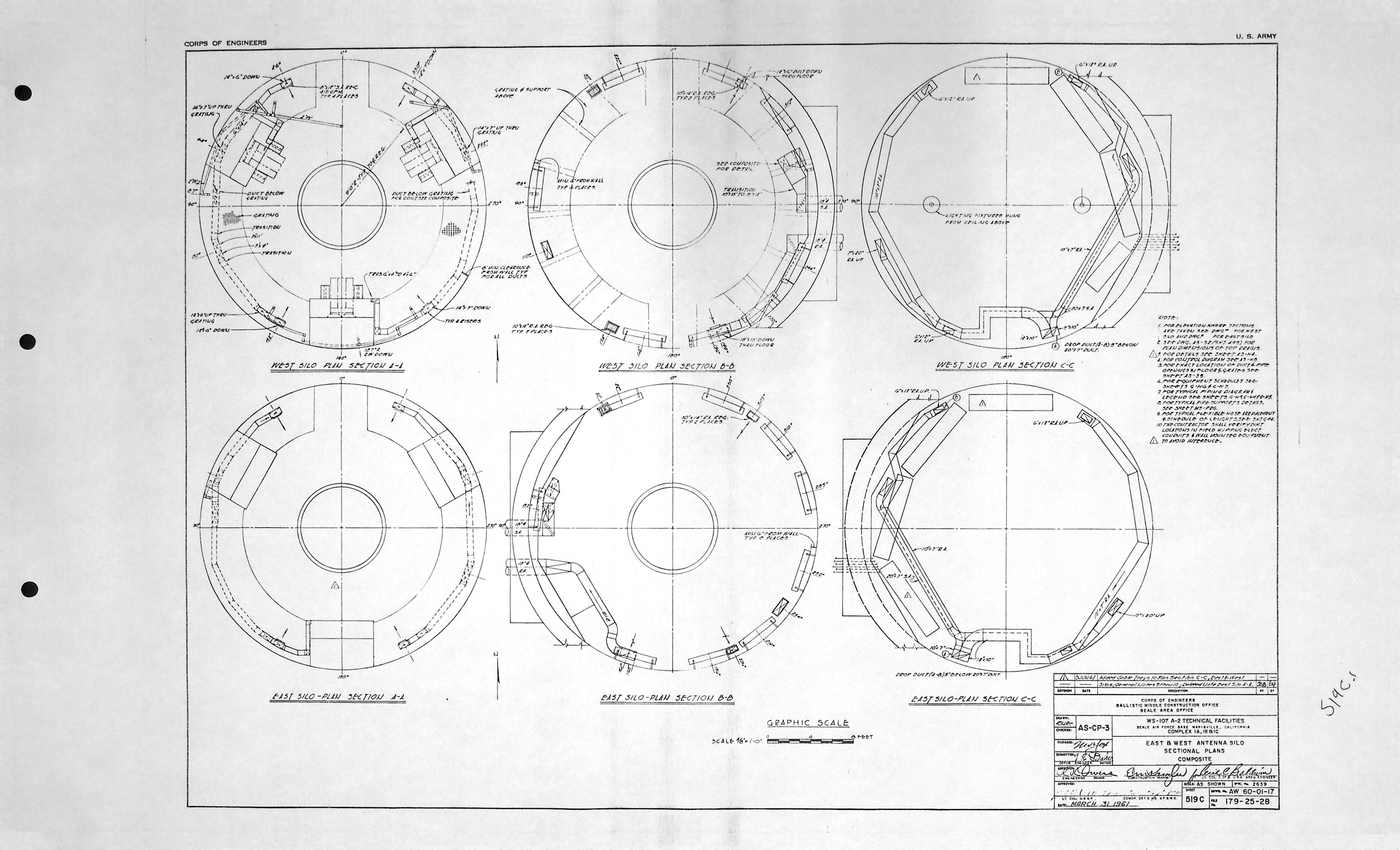
Antenna Silo - Composite drawings (3)
| Drawing Number | Description |
|---|---|
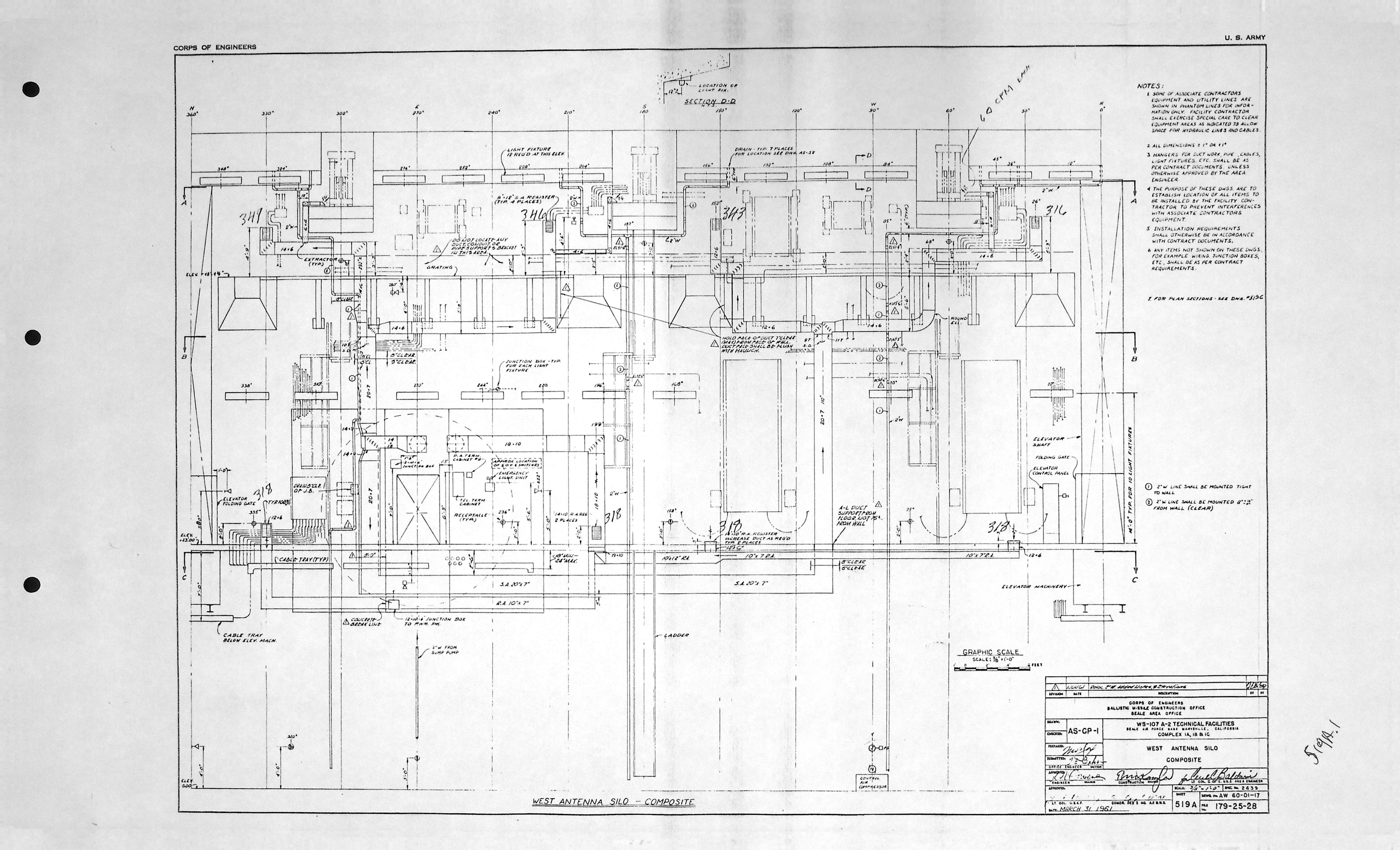
| AS-CP-1 | WEST COMPOSITE |
| AS-CP-2 | EAST COMPOSITE |
| AS-CP-3 | EAST & WEST SECTIONAL PLANS COMPOSITE |
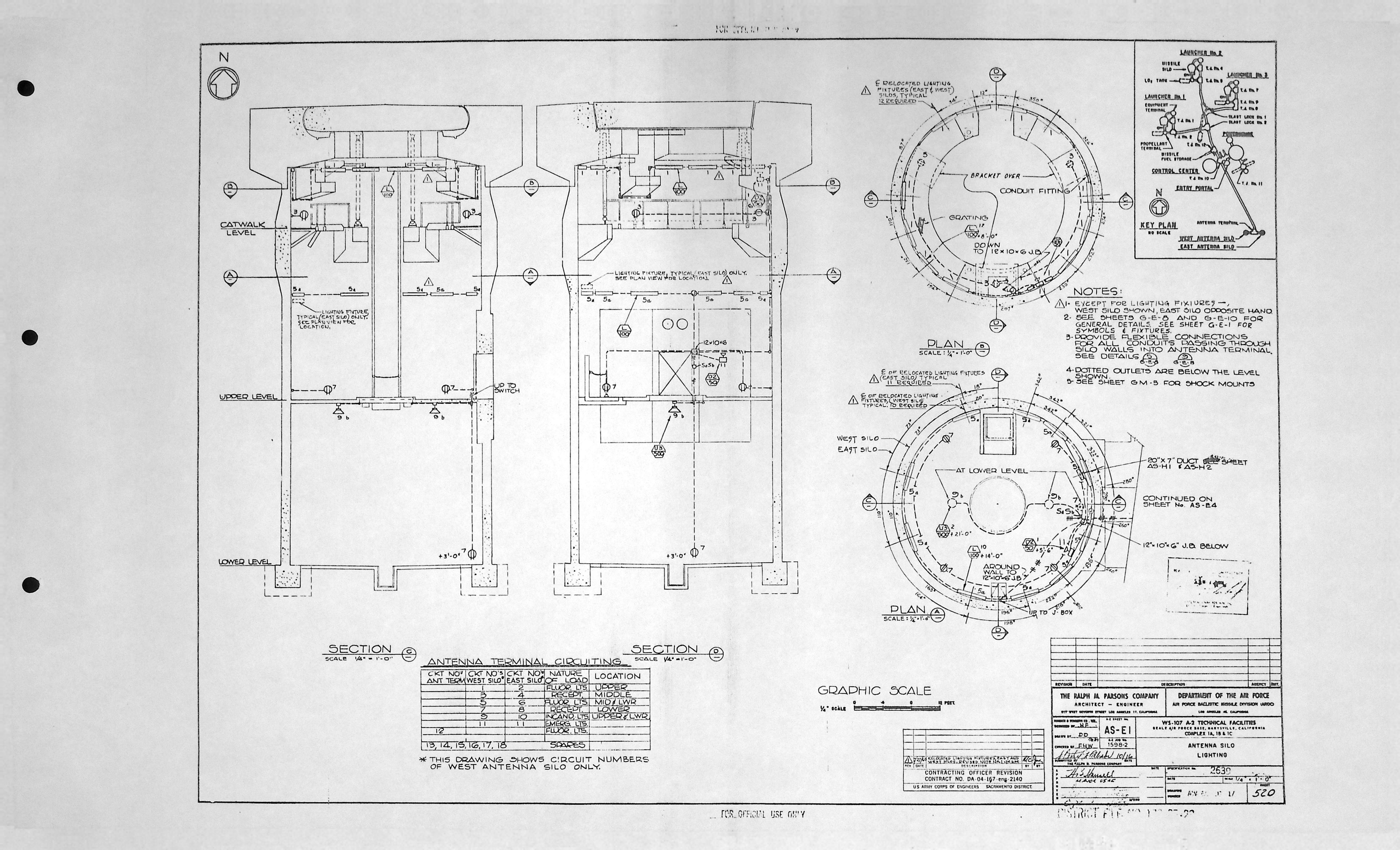
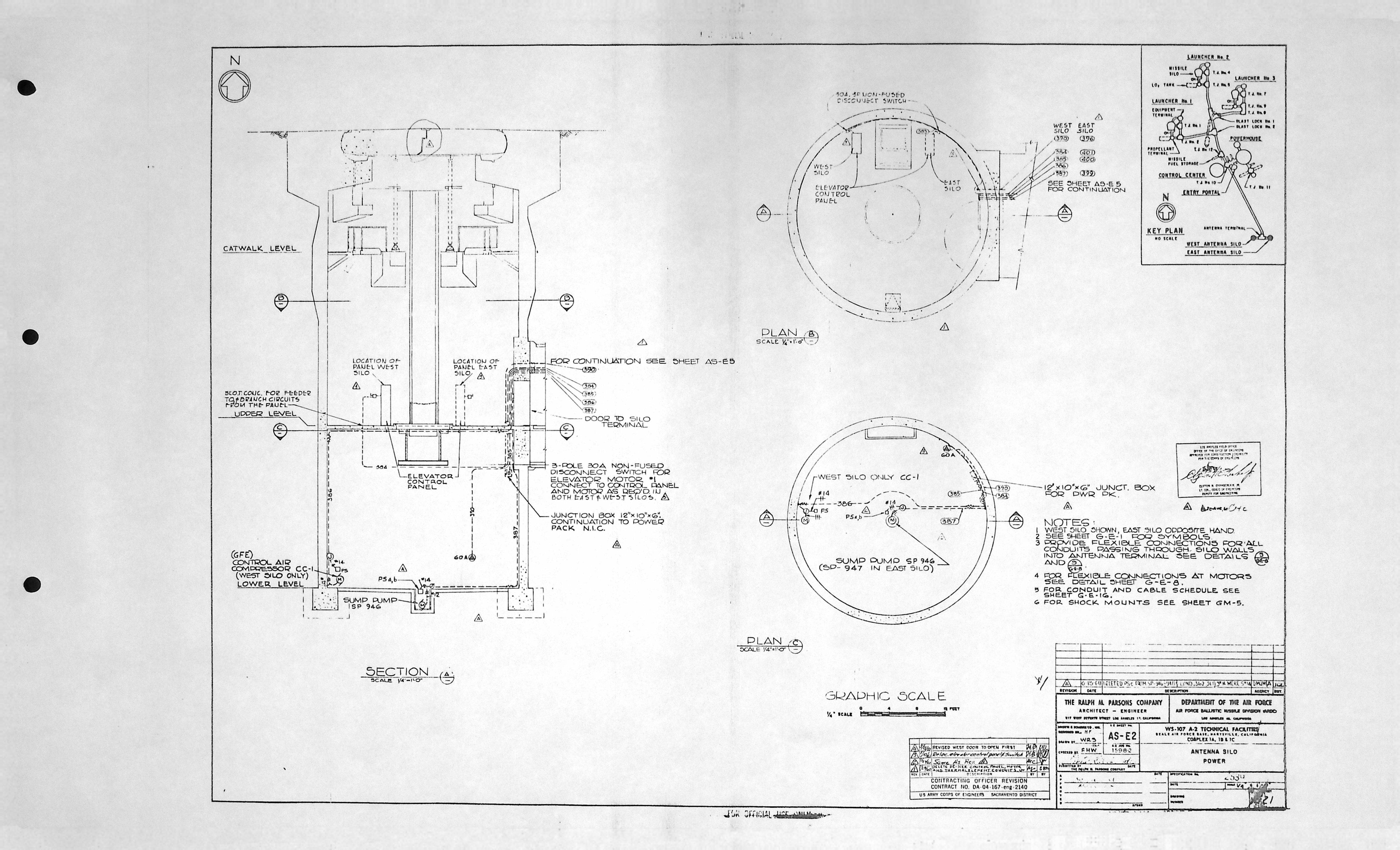
Antenna Silo - Electrical drawings (8)
| Drawing Number | Description |
|---|---|
| AS-E1 | LIGHTING |
| AS-E2 | POWER |
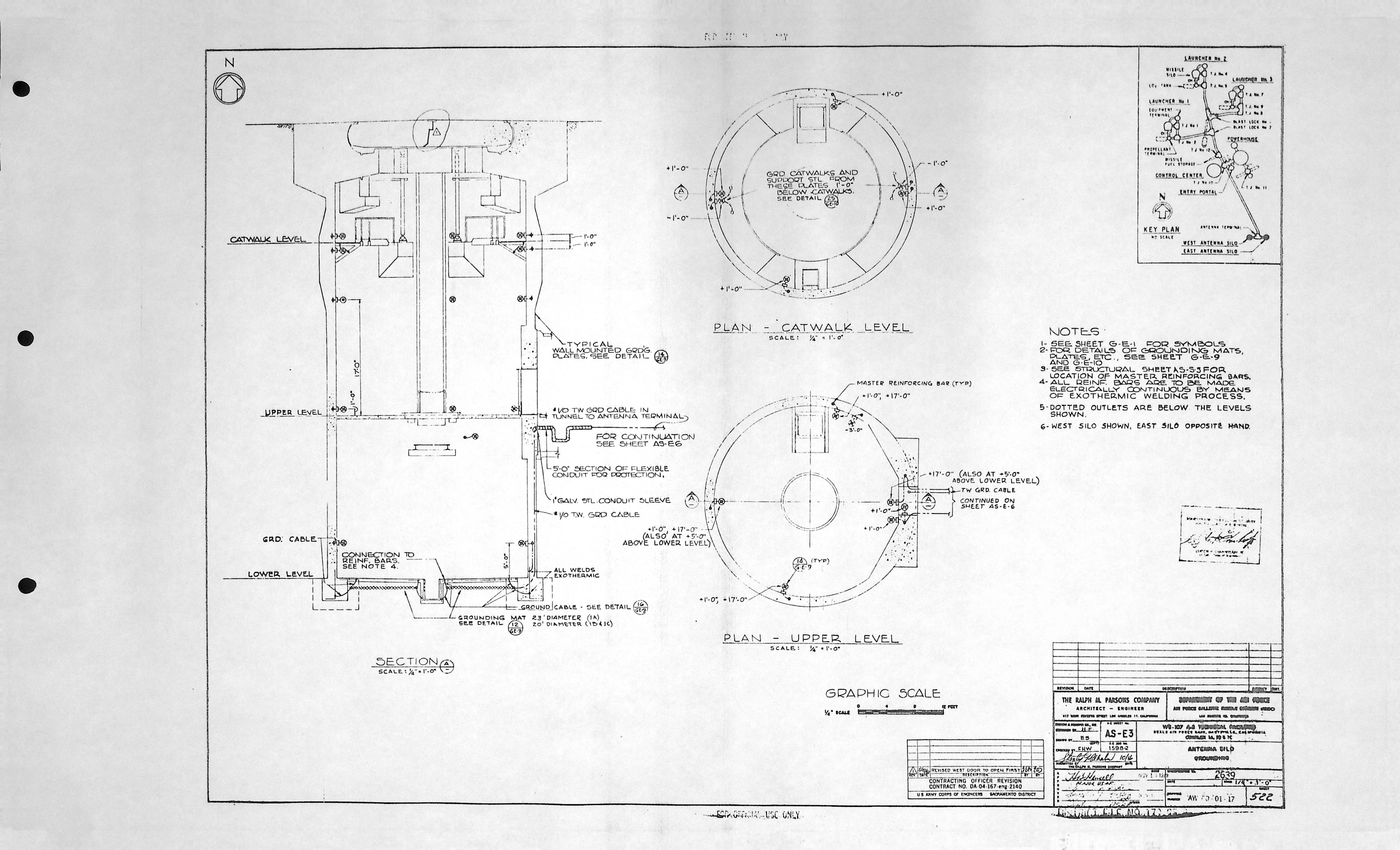
| AS-E3 | GROUNDING |
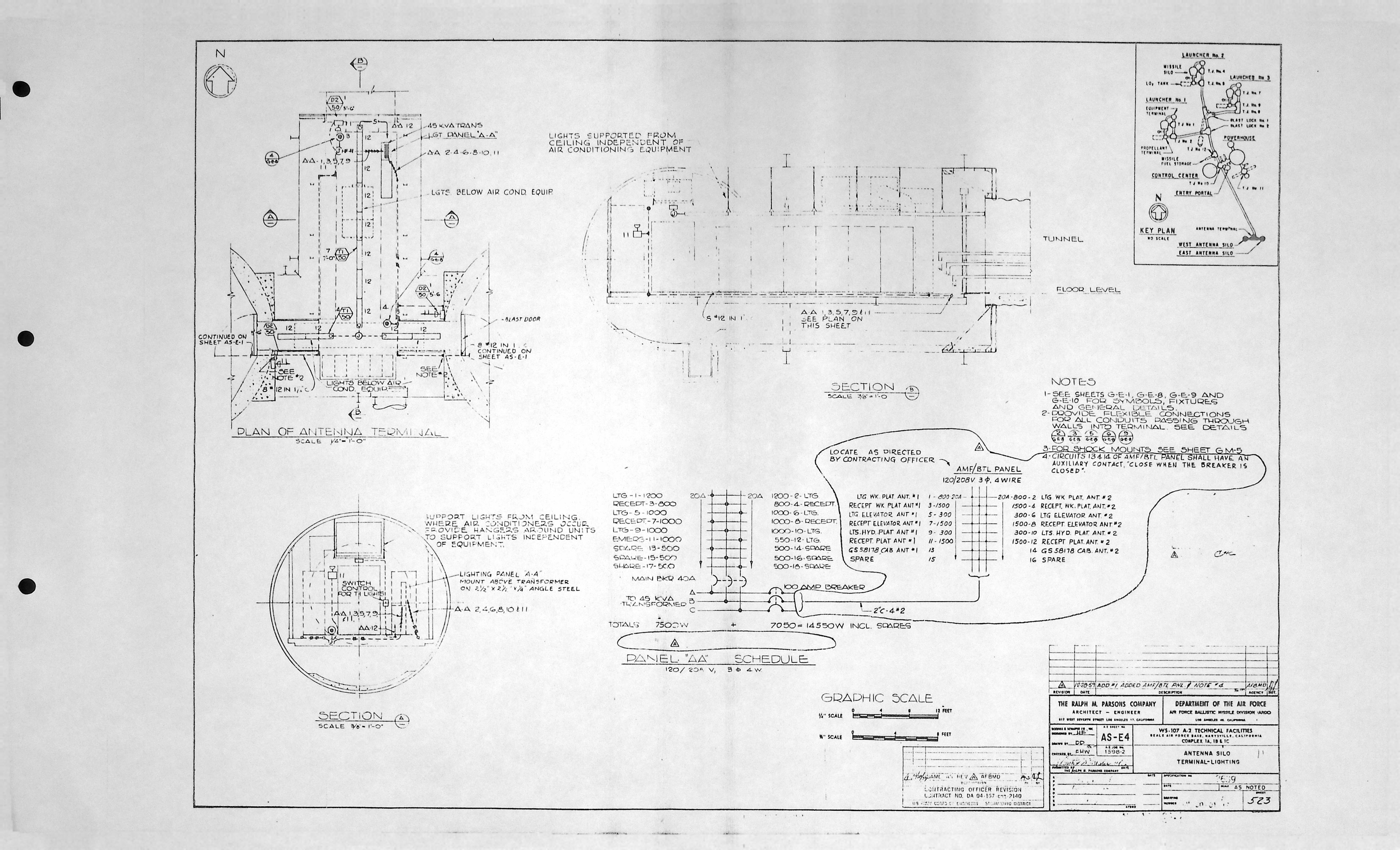
| AS-E4 | TERMINAL - LIGHTING |
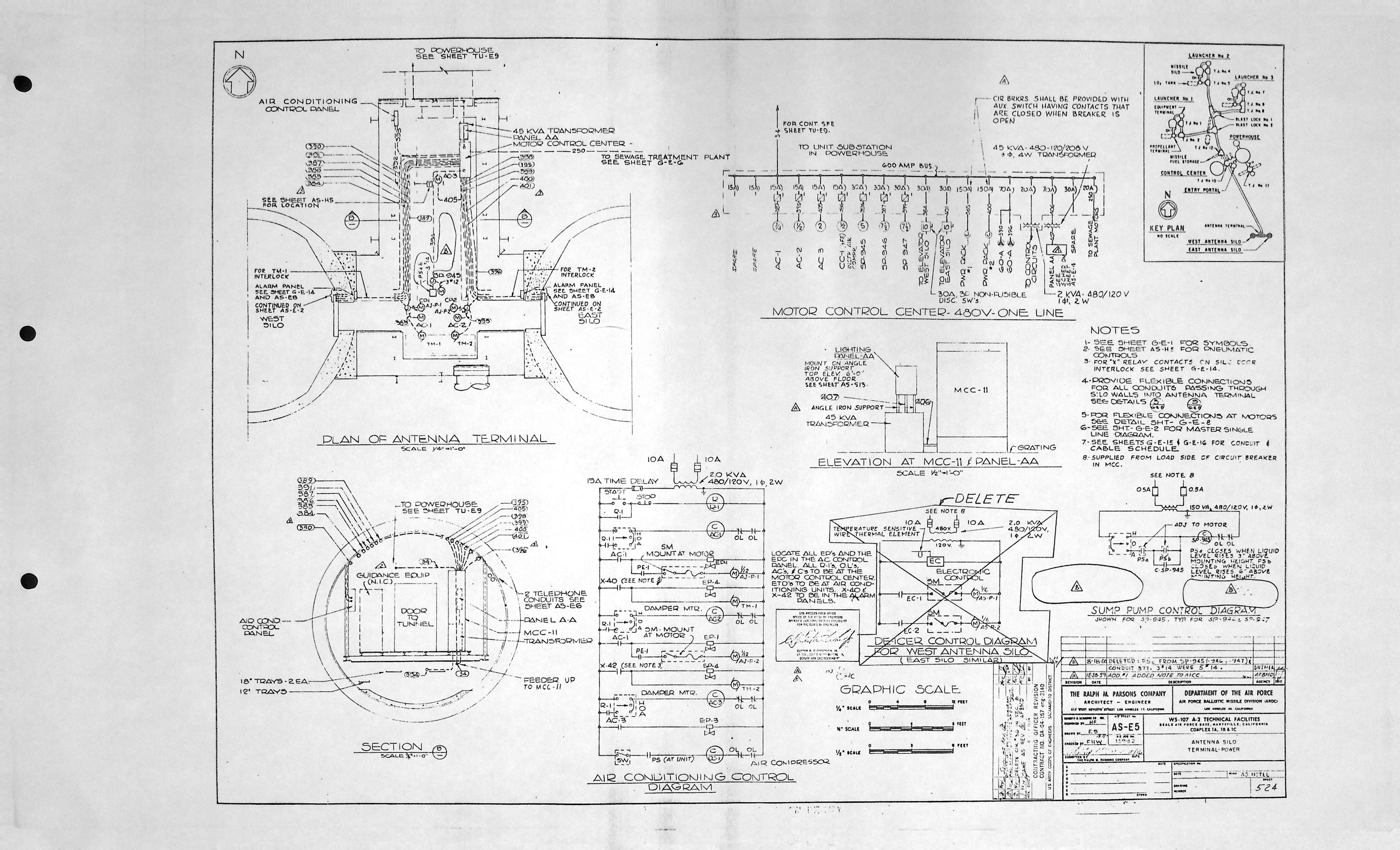
| AS-E5 | TERMINAL - POWER |
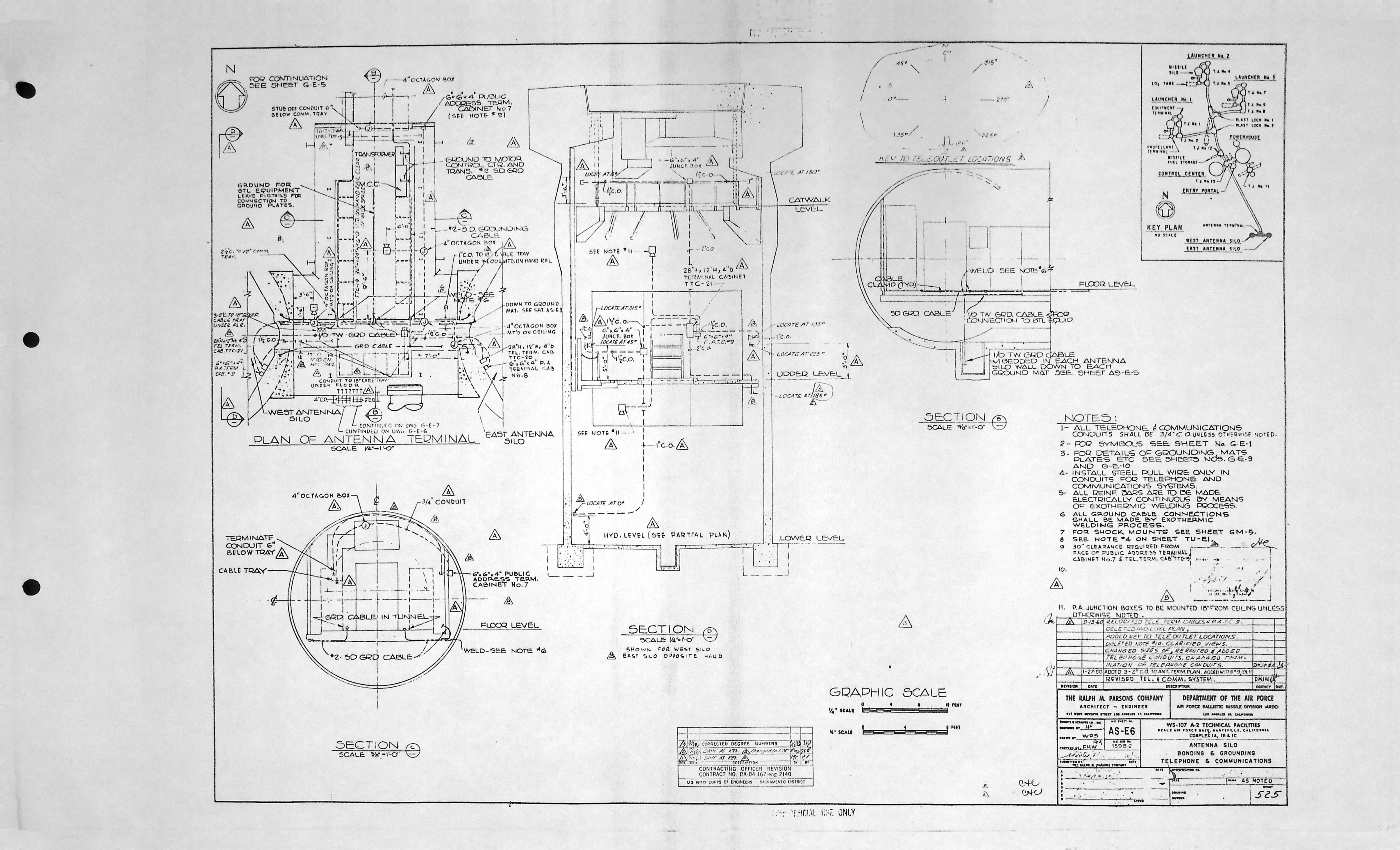
| AS-E6 | BONDING & GROUNDING, TELEPHONE & COMMUNICATIONS |
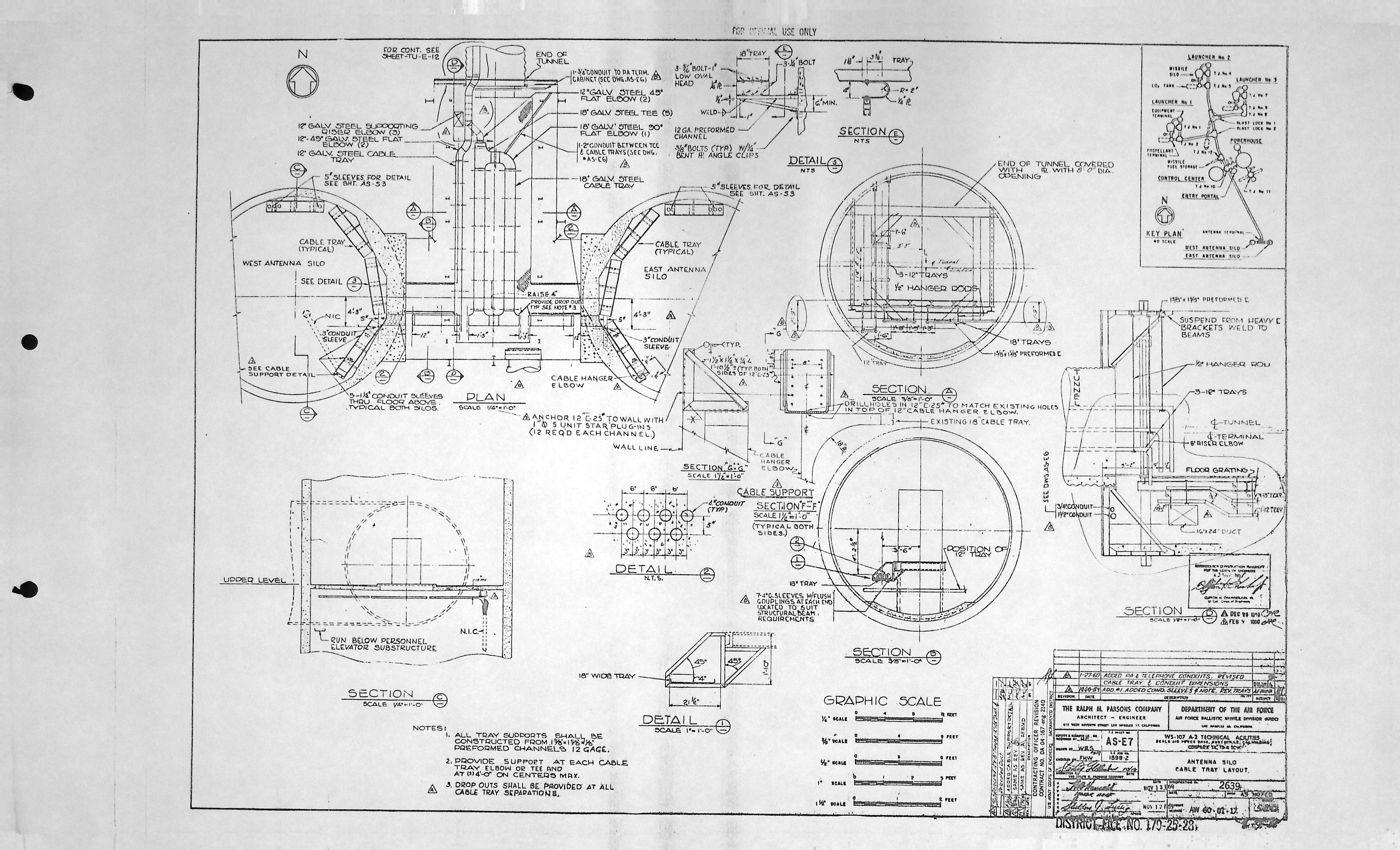
| AS-E7 | CABLE TRAY LAYOUT |
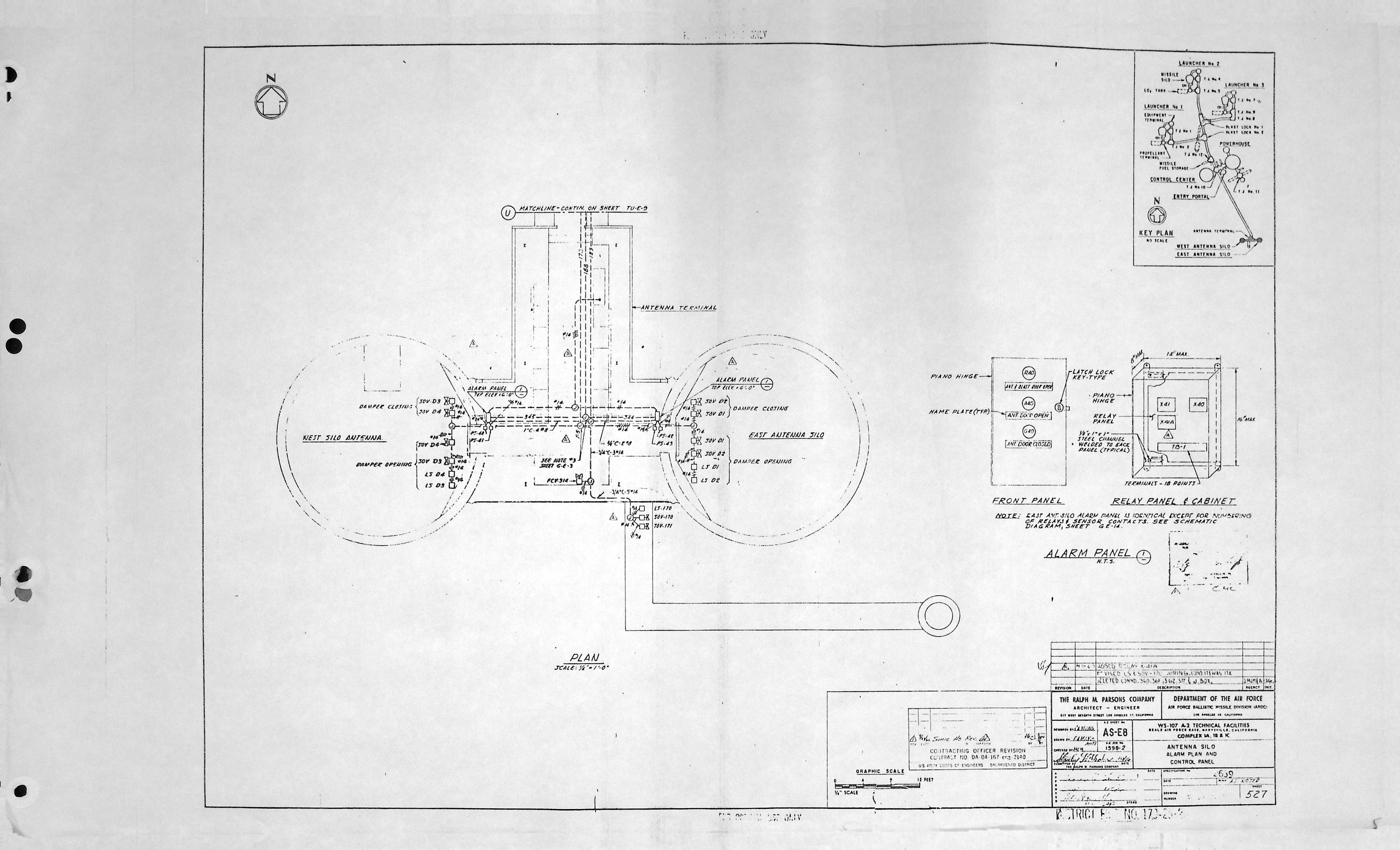
| AS-E8 | ALARM PLAN AND CONTROL PANEL |
Antenna Silo - HVAC drawings (3)
| Drawing Number | Description |
|---|---|
| AS-H1 | DELETED |
| AS-H2 | DELETED |
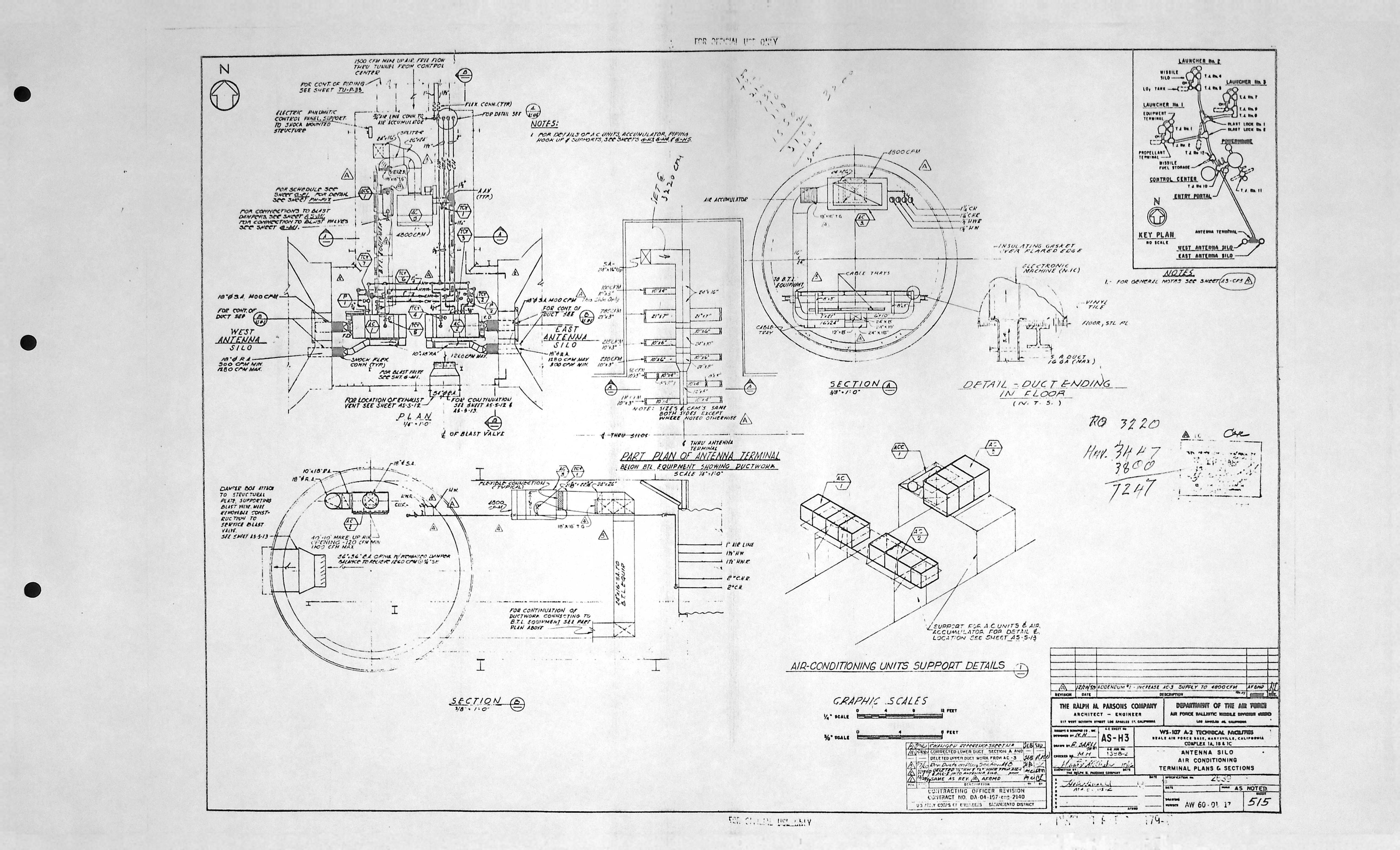
| AS-H3 | AIR CONDITIONING TERMINAL PLANS & SECTIONS |
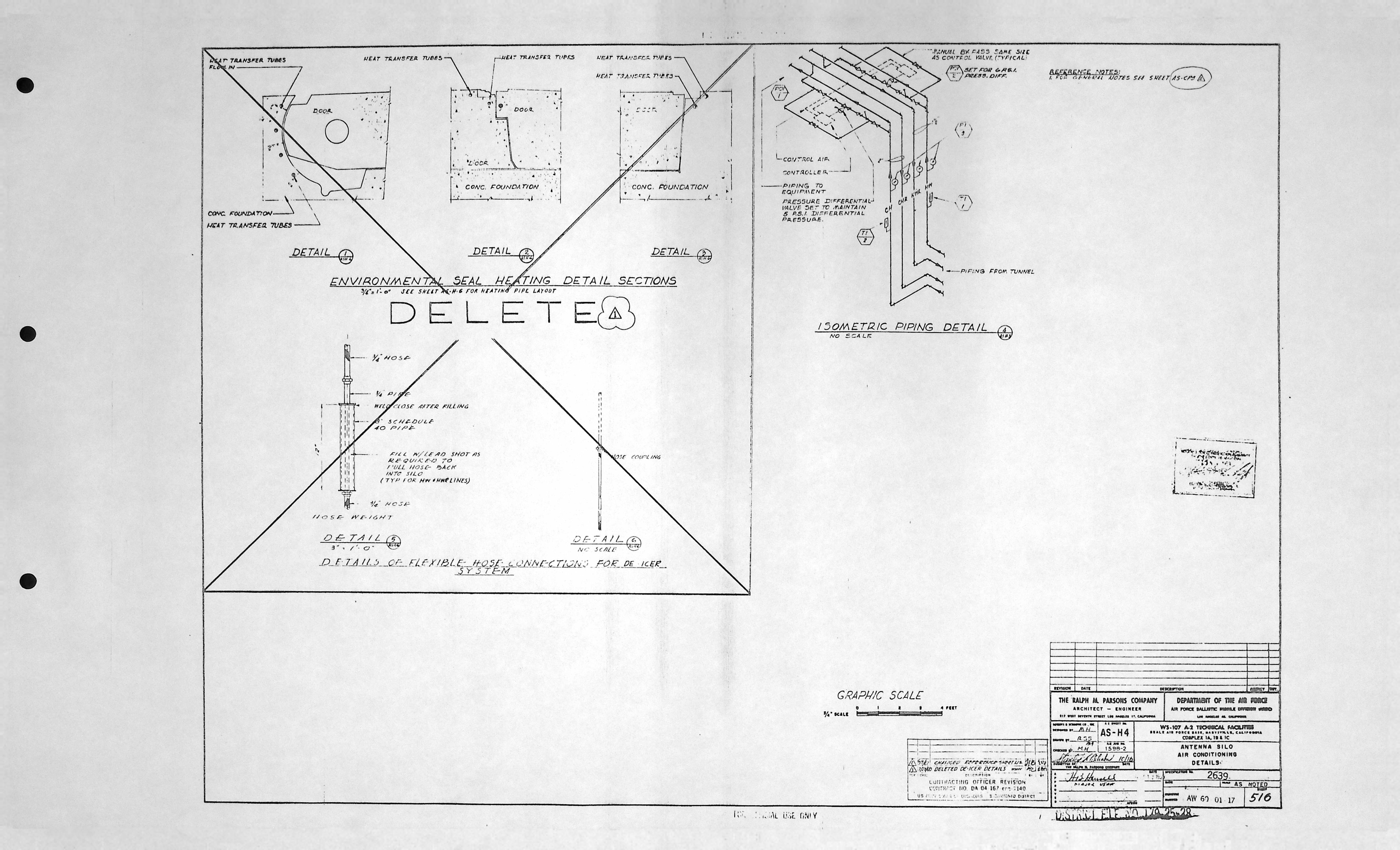
| AS-H4 | AIR CONDITIONING DETAILS |
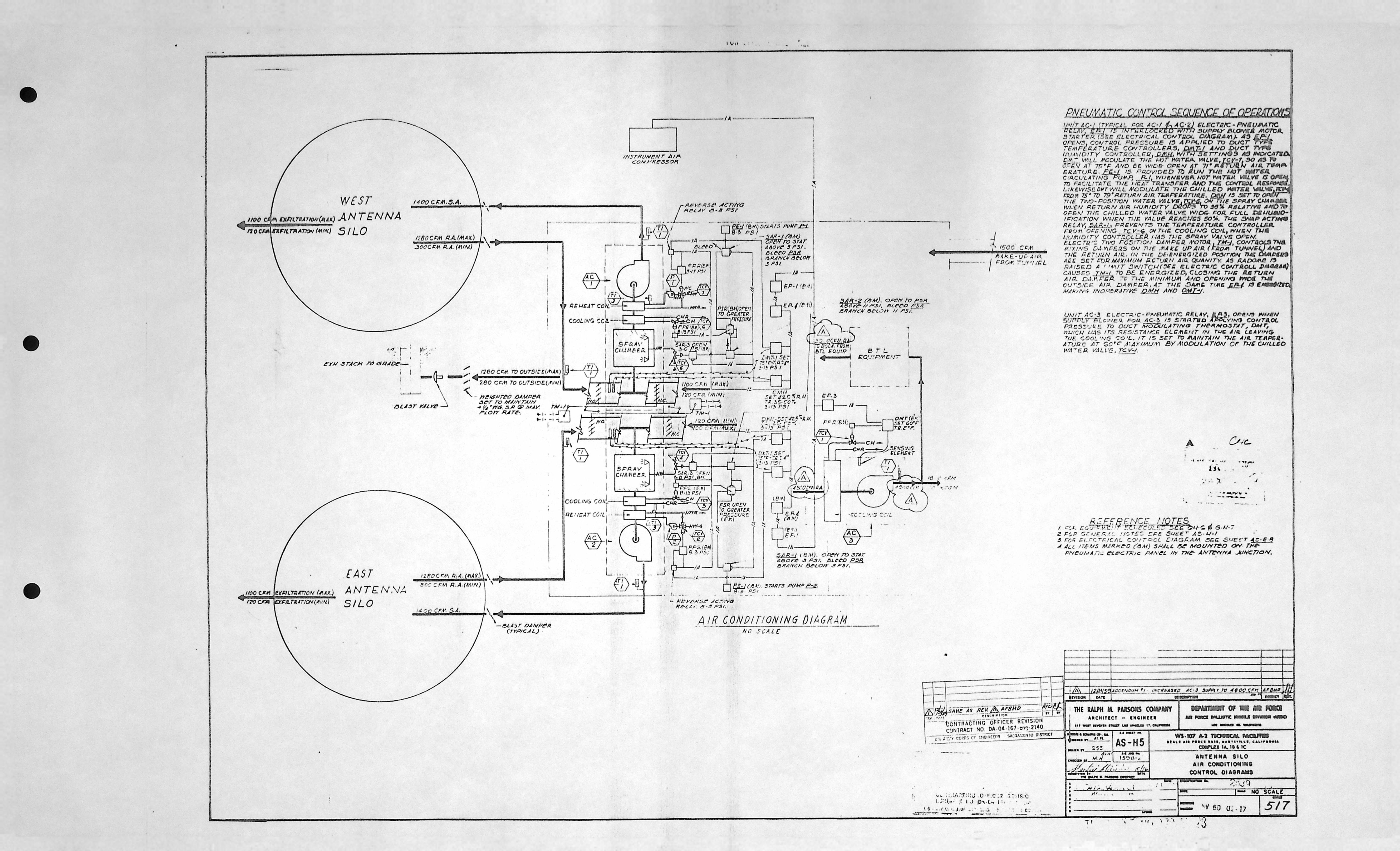
| AS-H5 | AIR CONDITIONING CONTROL DIAGRAMS |
Antenna Silo - Mechanical drawings (1)
| Drawing Number | Description |
|---|---|
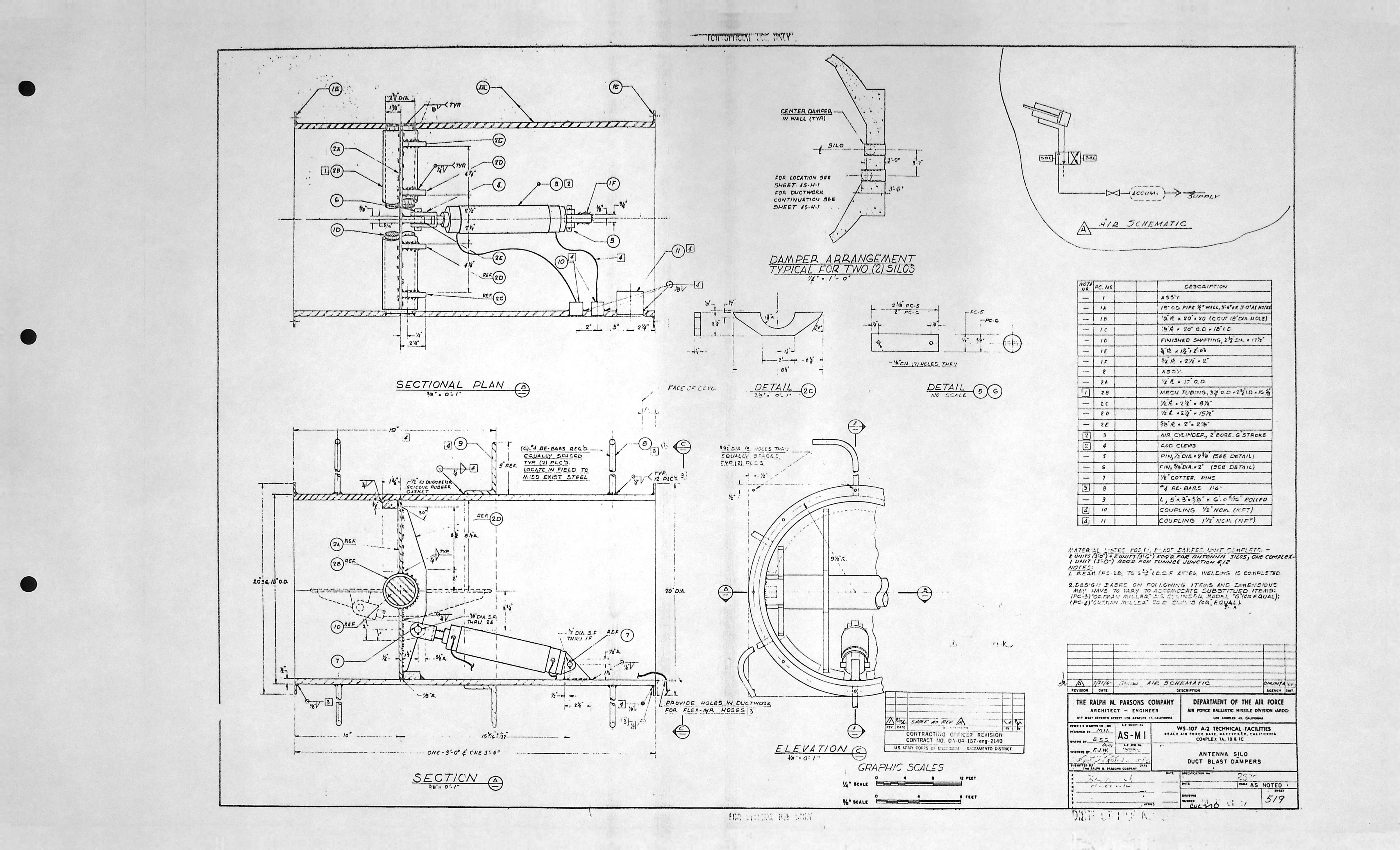
| AS-M1 | DUCT BLAST DAMPERS |
Antenna Silo - Plumbing/Piping drawings (2)
| Drawing Number | Description |
|---|---|
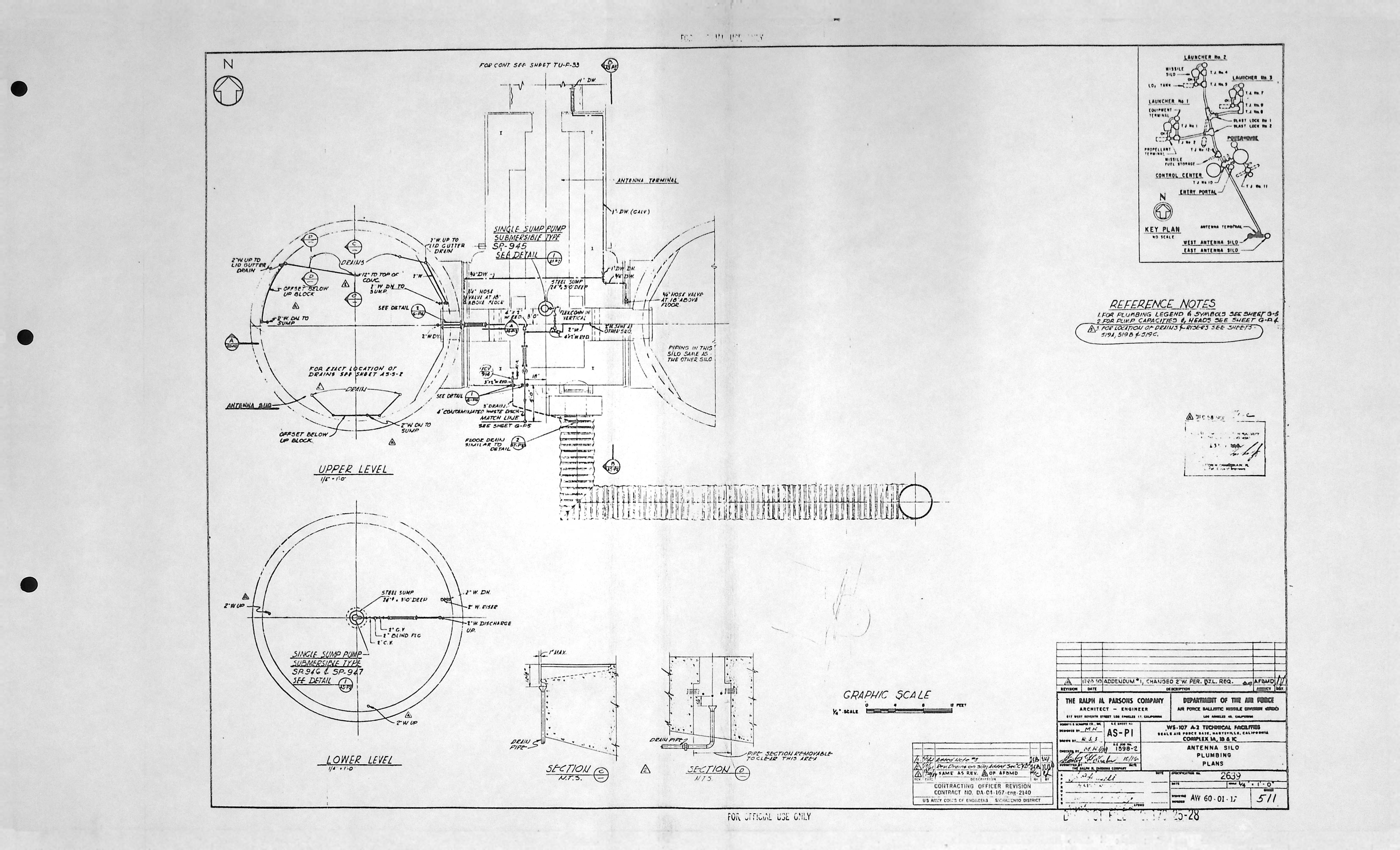
| AS-P1 | PLUMBING PLANS |
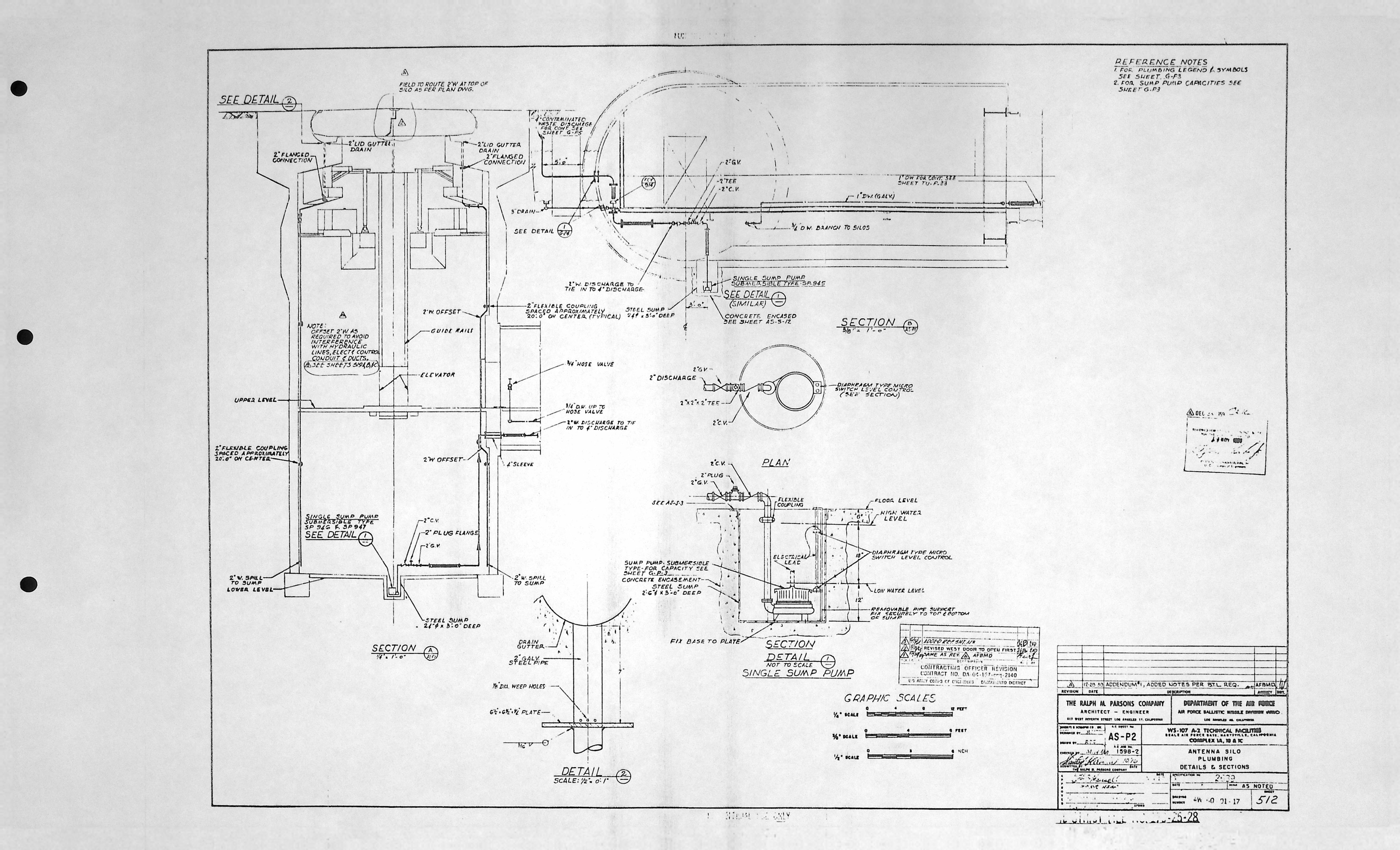
| AS-P2 | PLUMBING DETAILS AND SECTIONS |
Antenna Silo - Structural drawings (19)
| Drawing Number | Description |
|---|---|
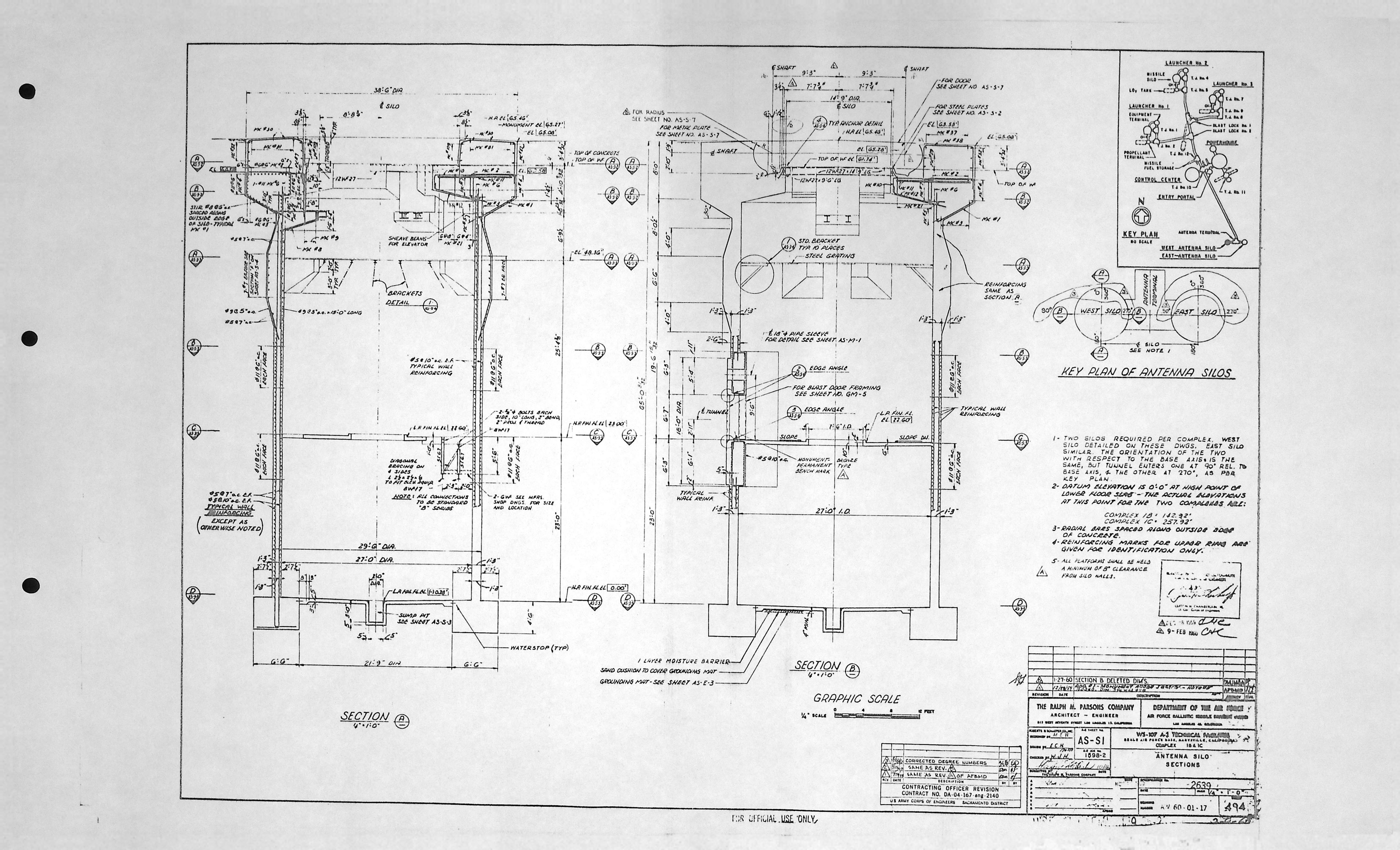
| AS-S1 | SECTIONS |
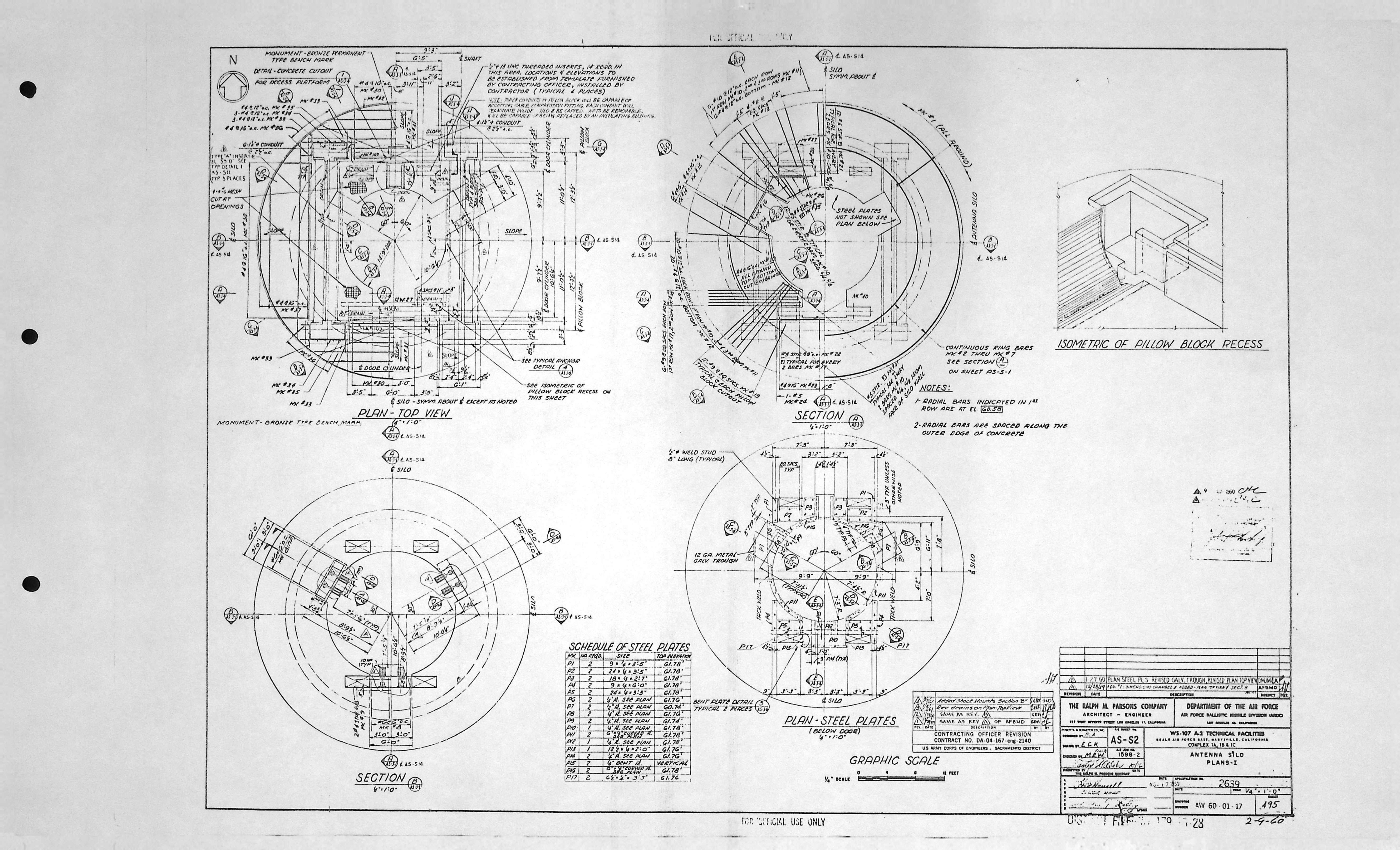
| AS-S2 | PLANS - I |
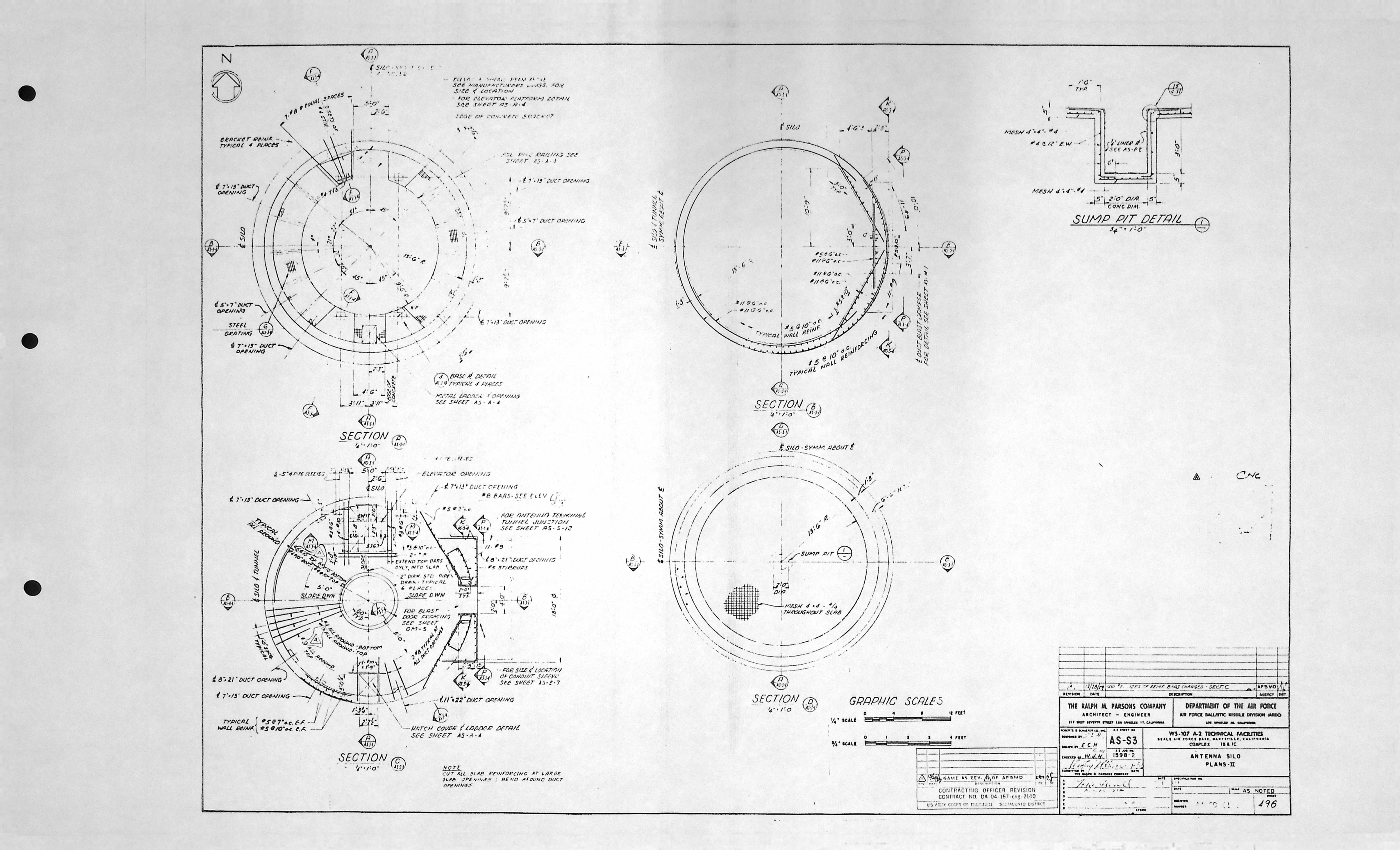
| AS-S3 | PLANS - II |
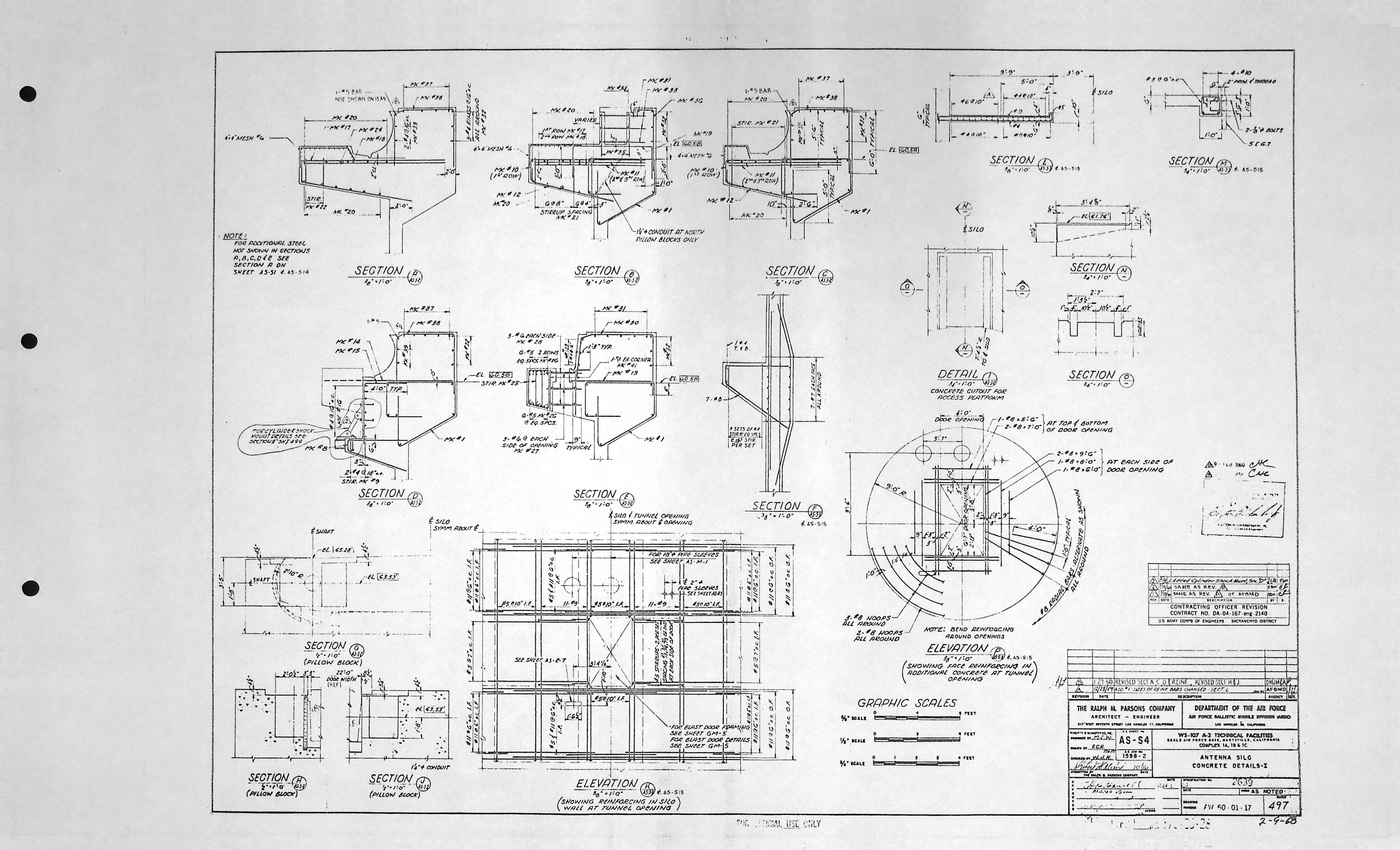
| AS-S4 | CONCRETE DETAILS - I |
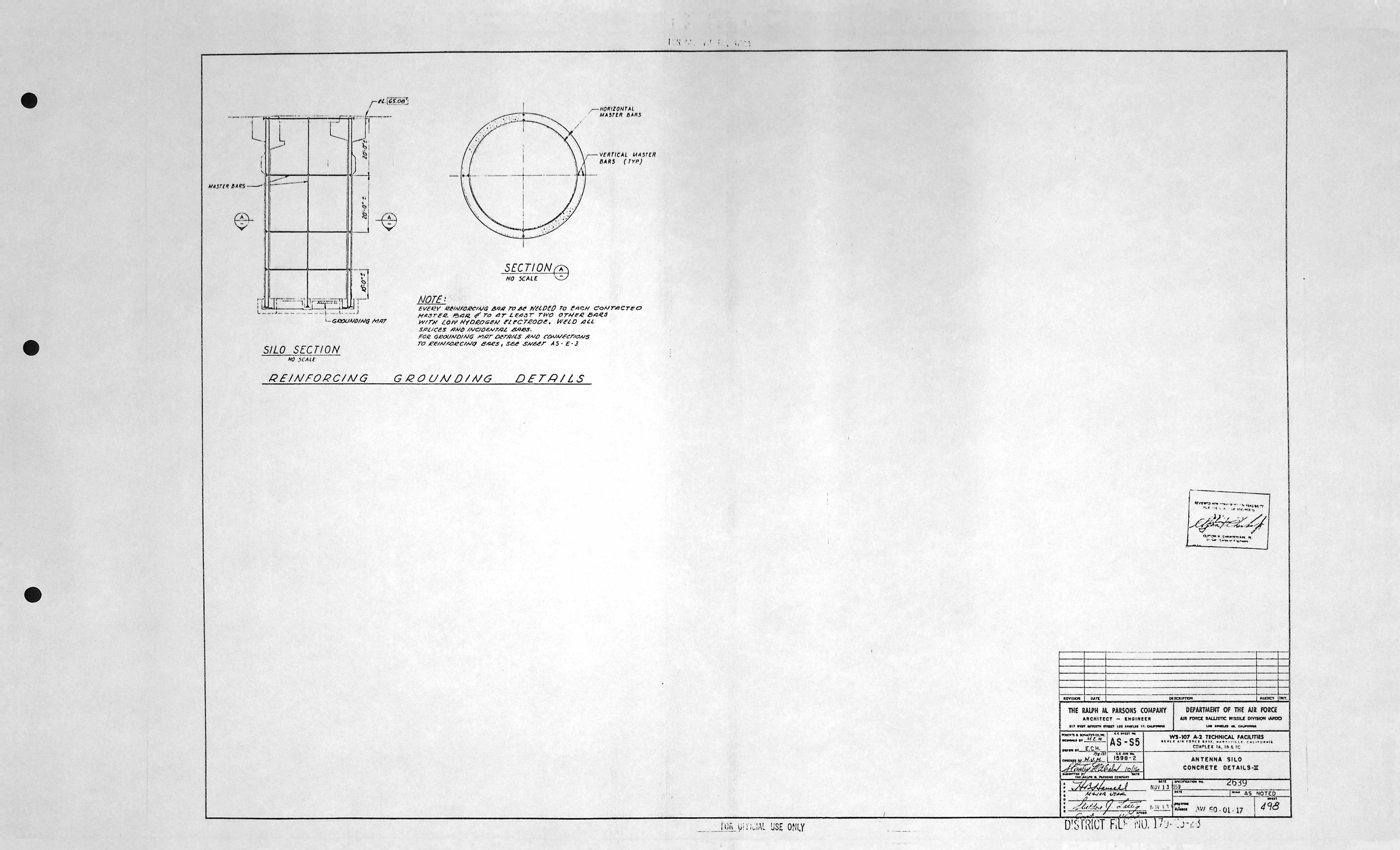
| AS-S5 | CONCRETE DETAILS - II |
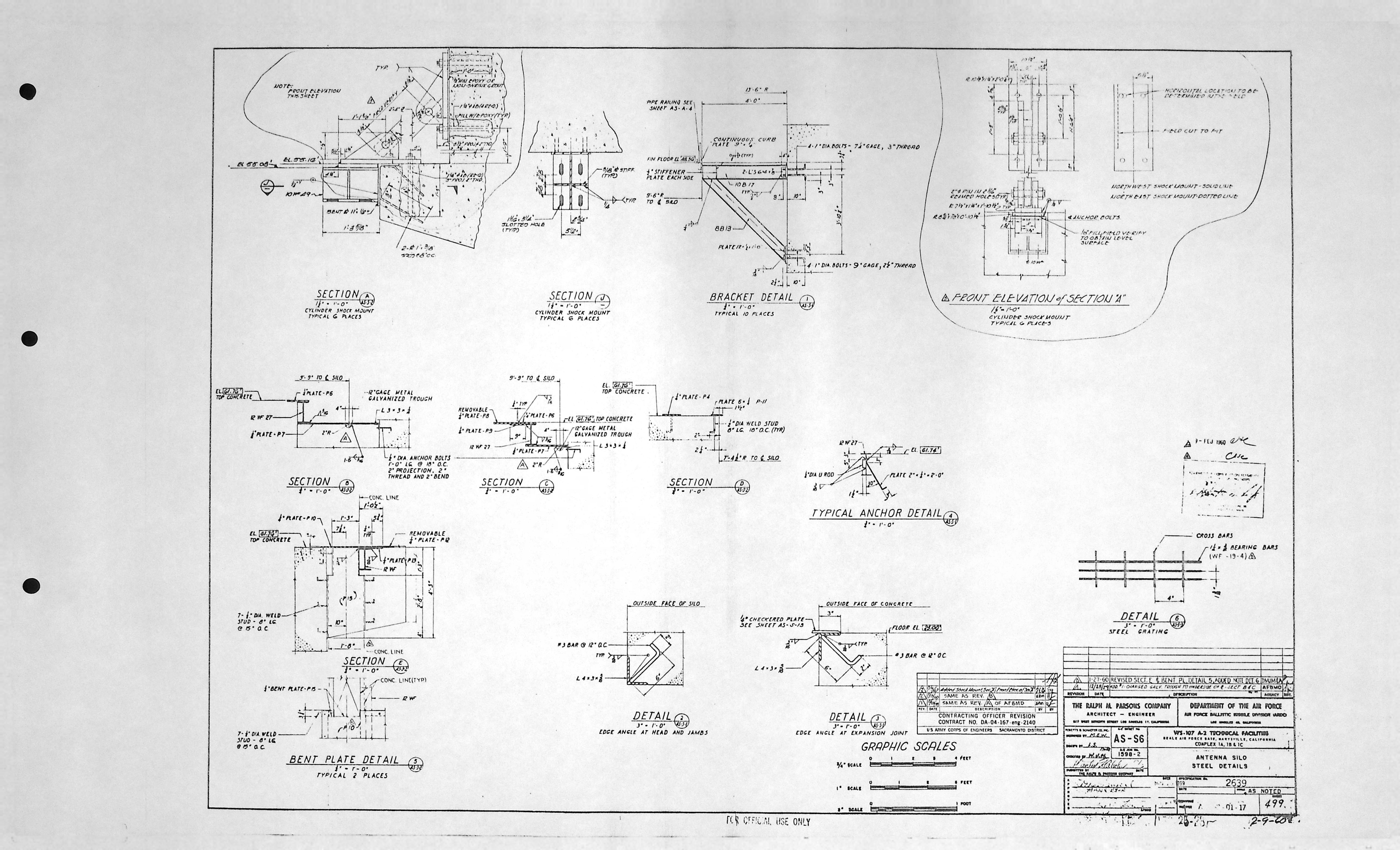
| AS-S6 | STEEL DETAILS |
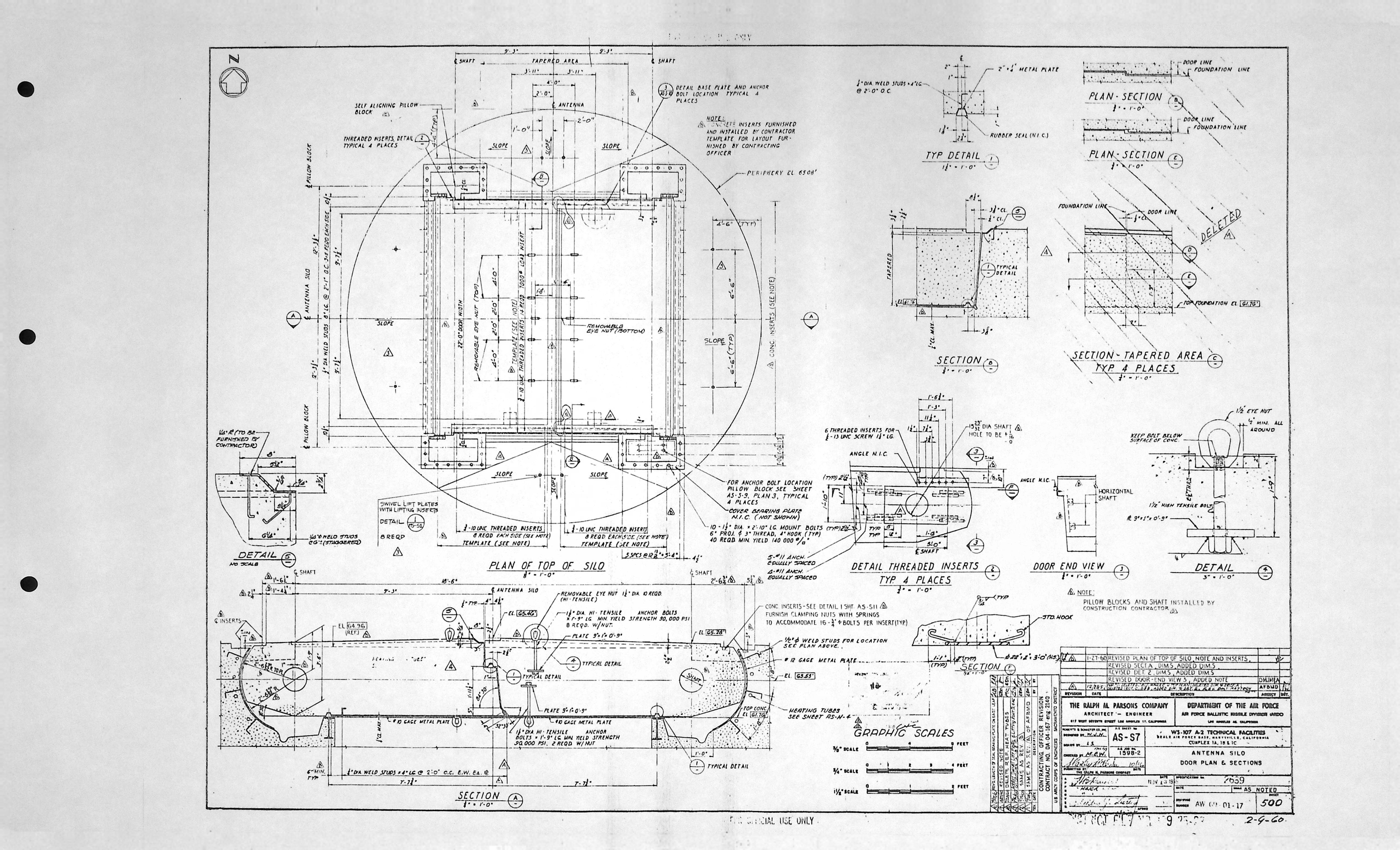
| AS-S7 | DOOR PLAN & SECTIONS |
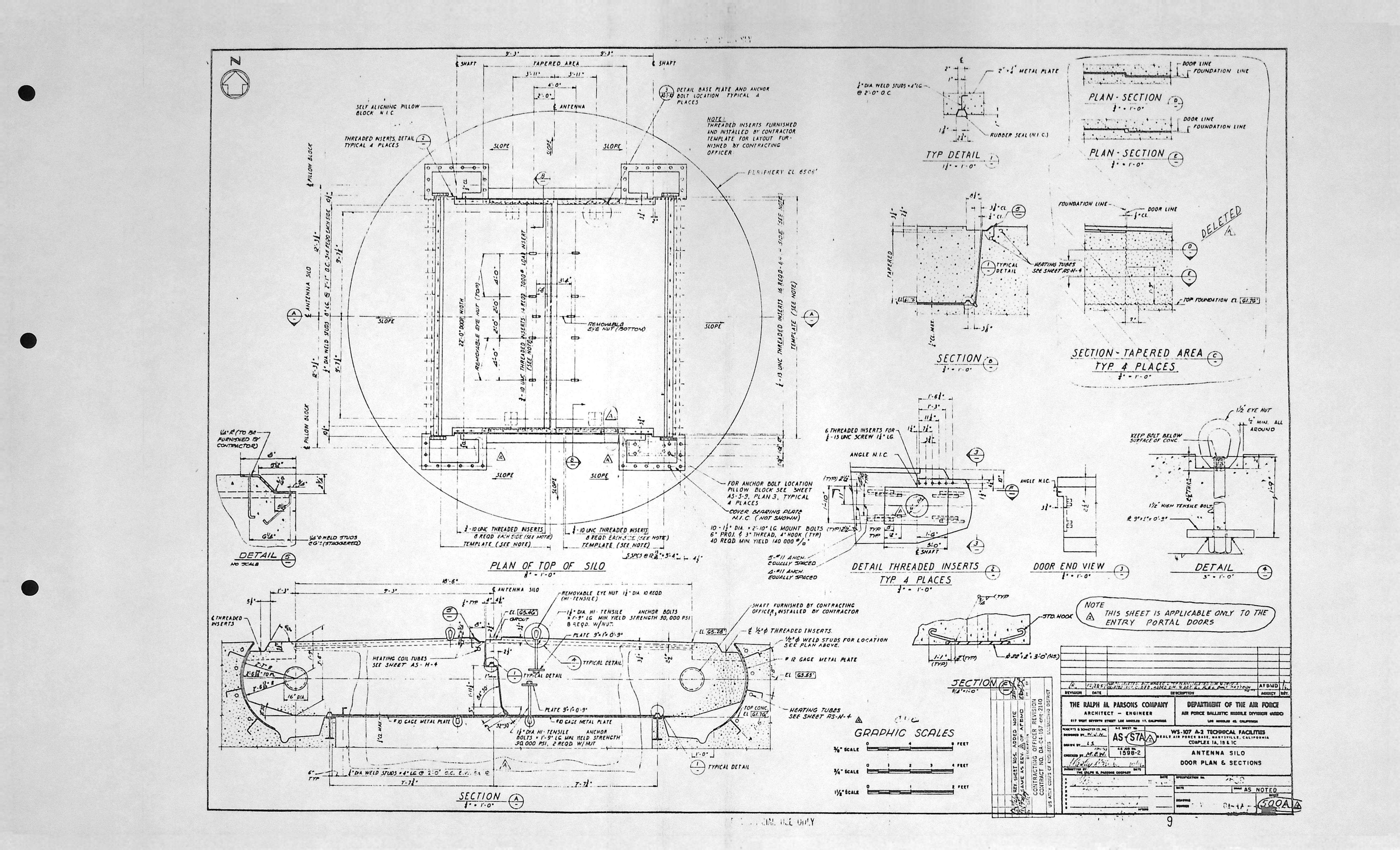
| AS-S7A | DOOR PLAN & SECTIONS |
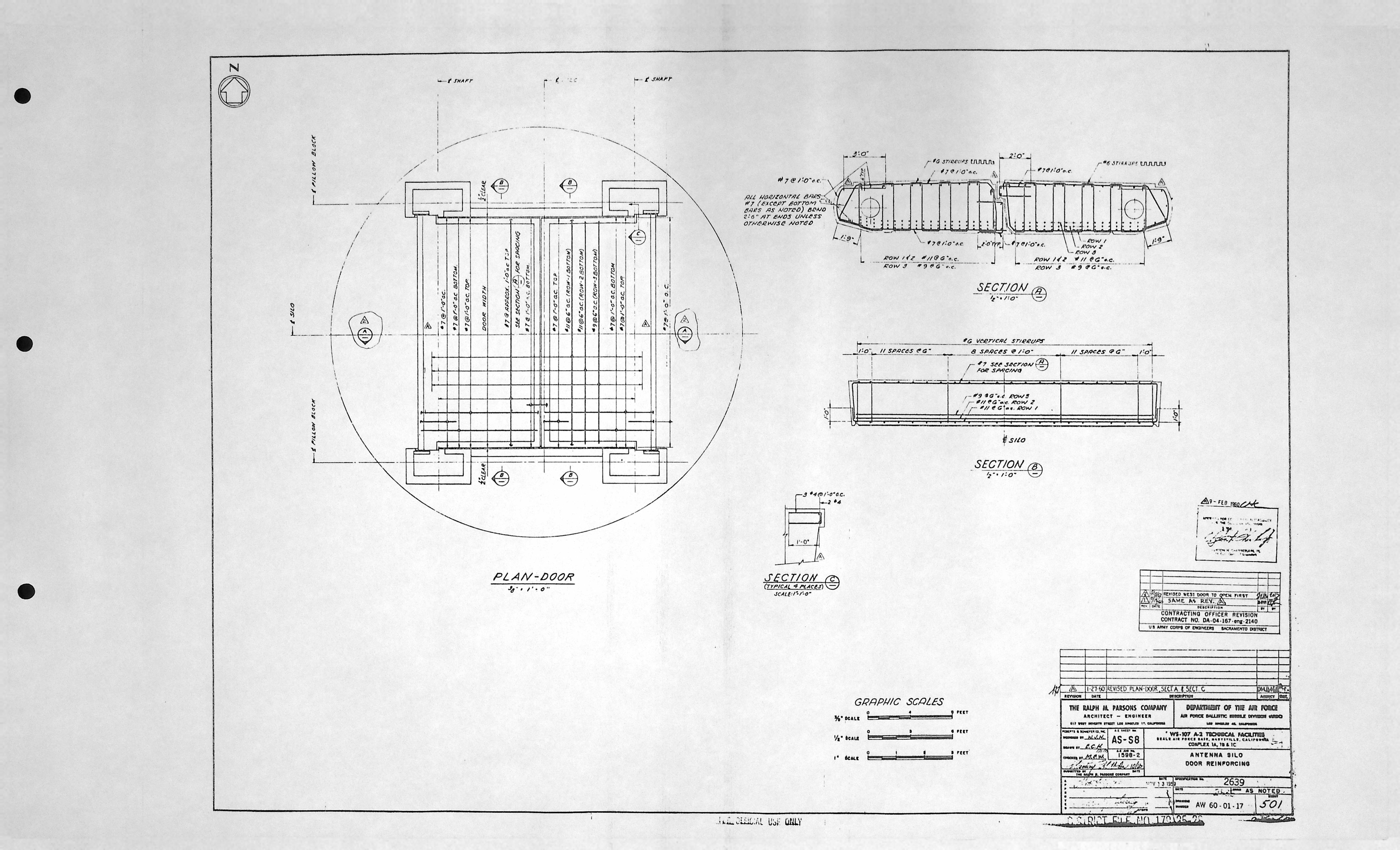
| AS-S8 | DOOR REINFORCING |
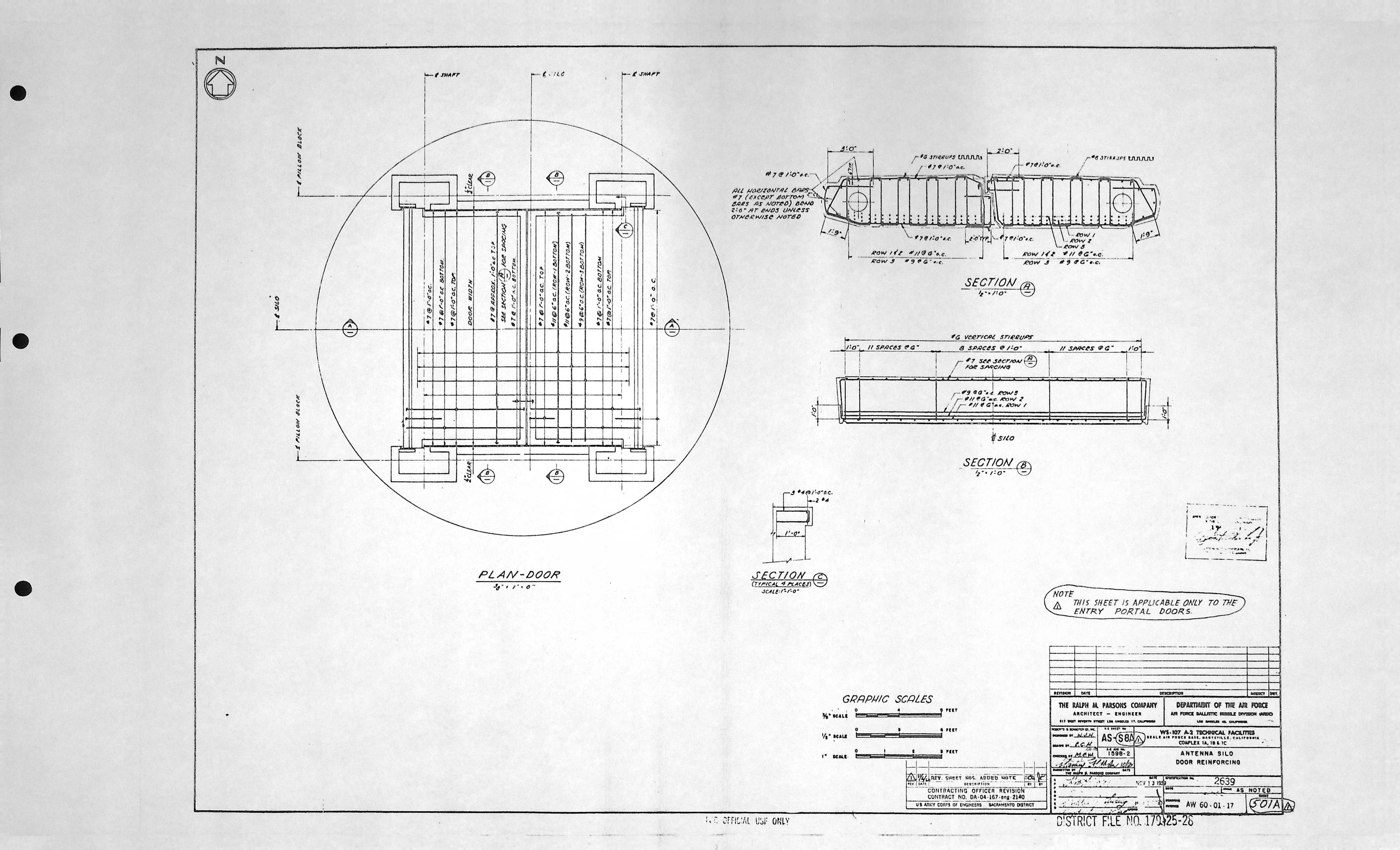
| AS-S8A | DOOR REINFORCING |
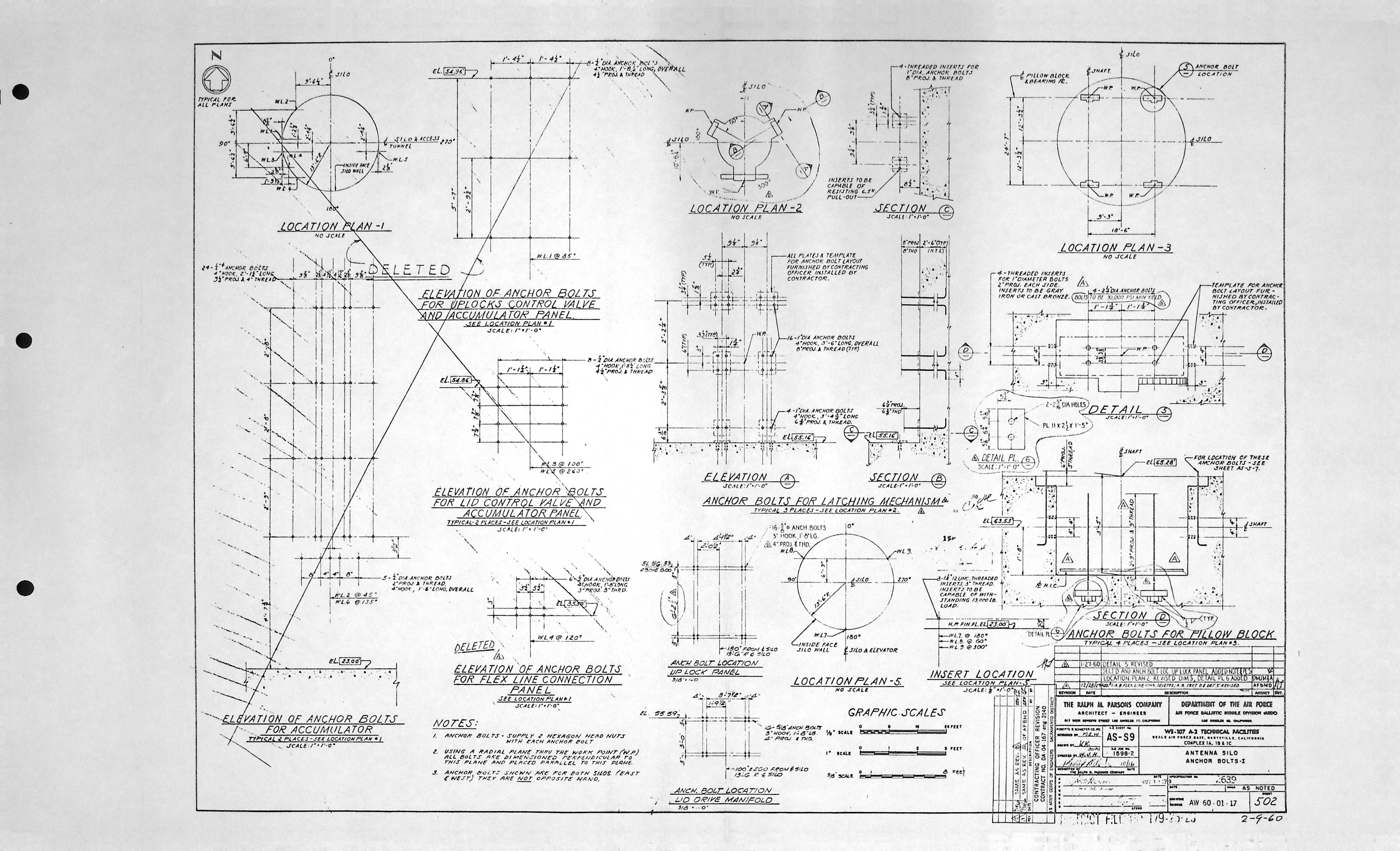
| AS-S9 | ANCHOR BOLTS - I |
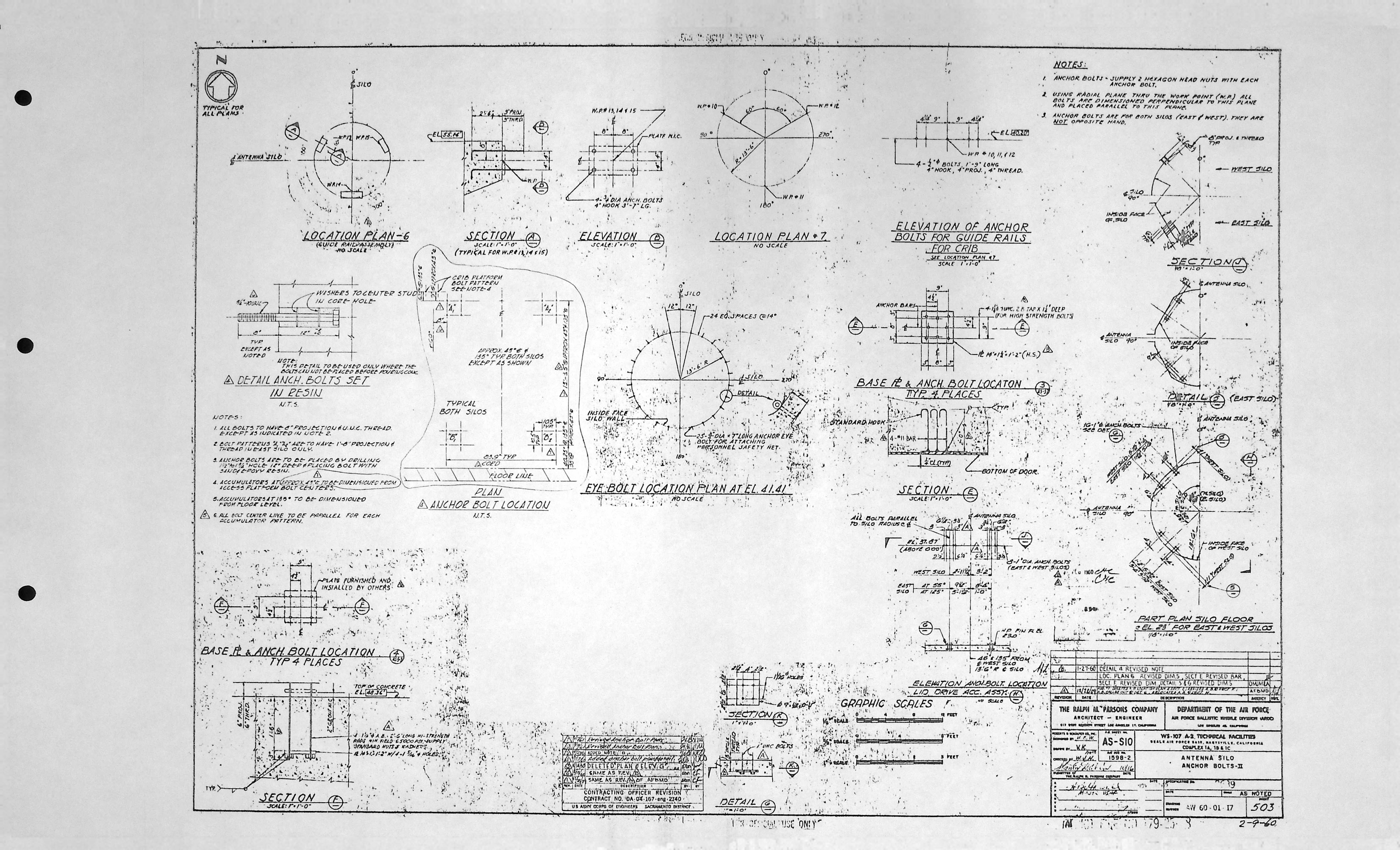
| AS-S10 | ANCHOR BOLTS - II |
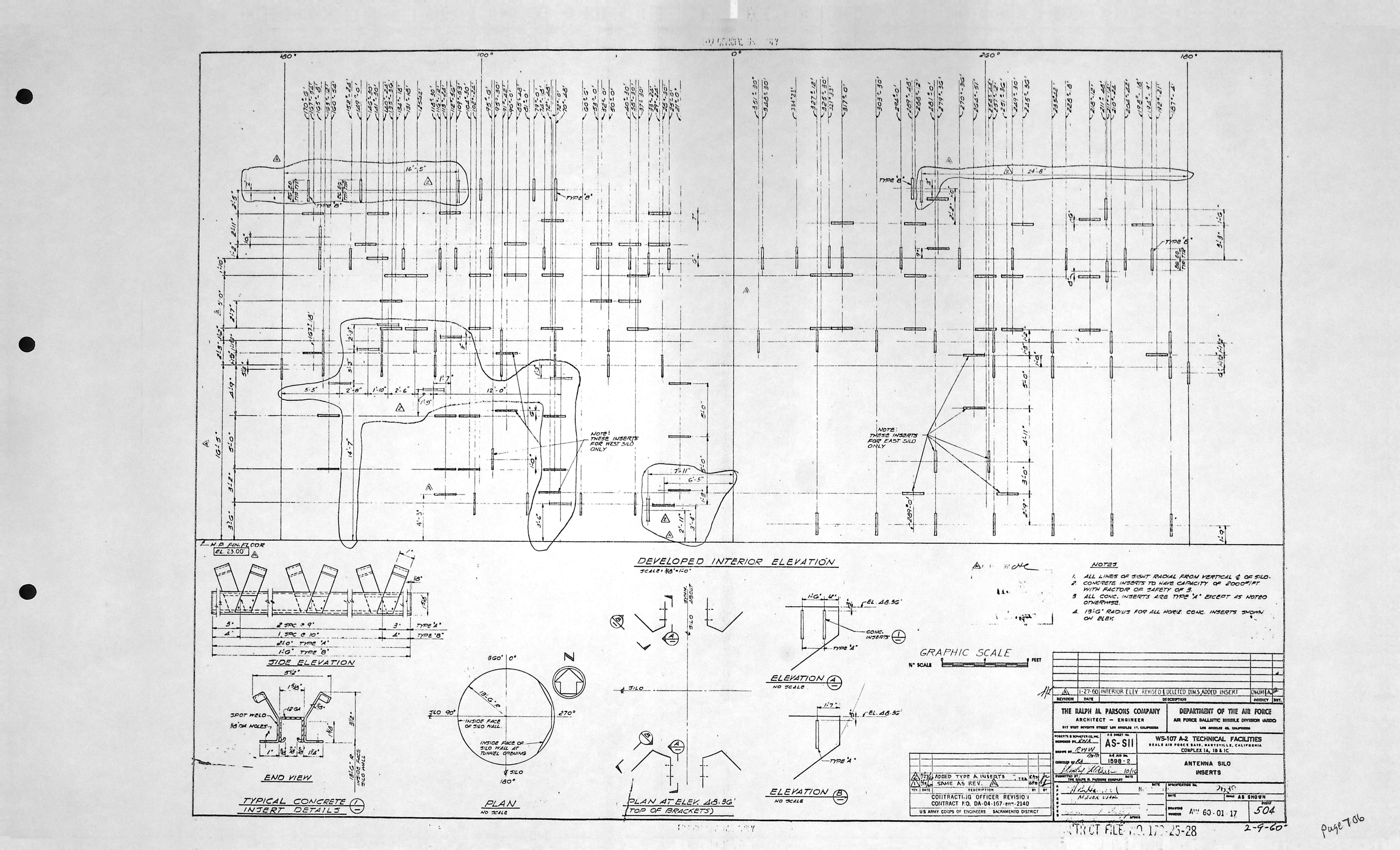
| AS-S11 | INSERTS |
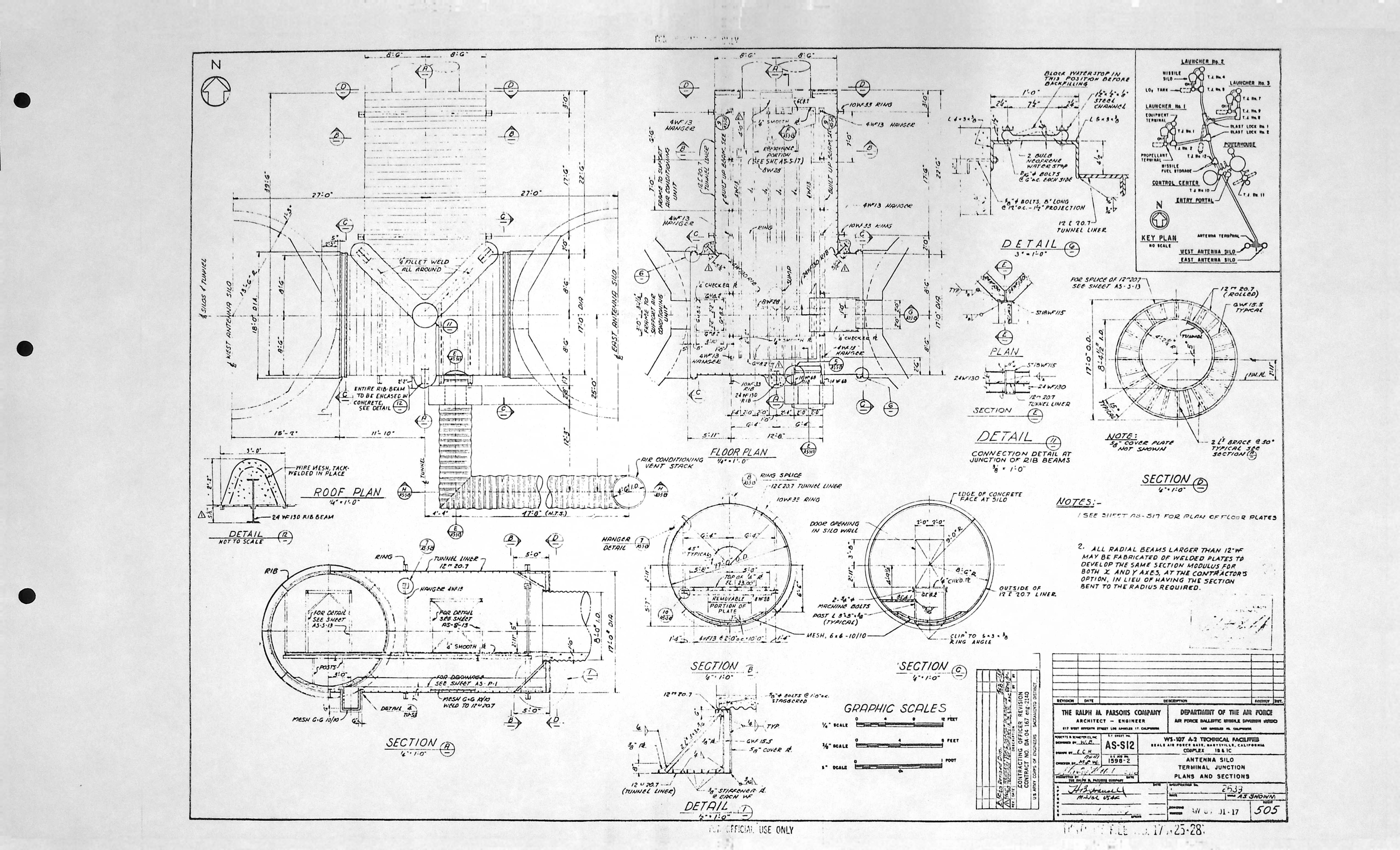
| AS-S12 | TERMINAL JUNCTION PLAN & SECTIONS |
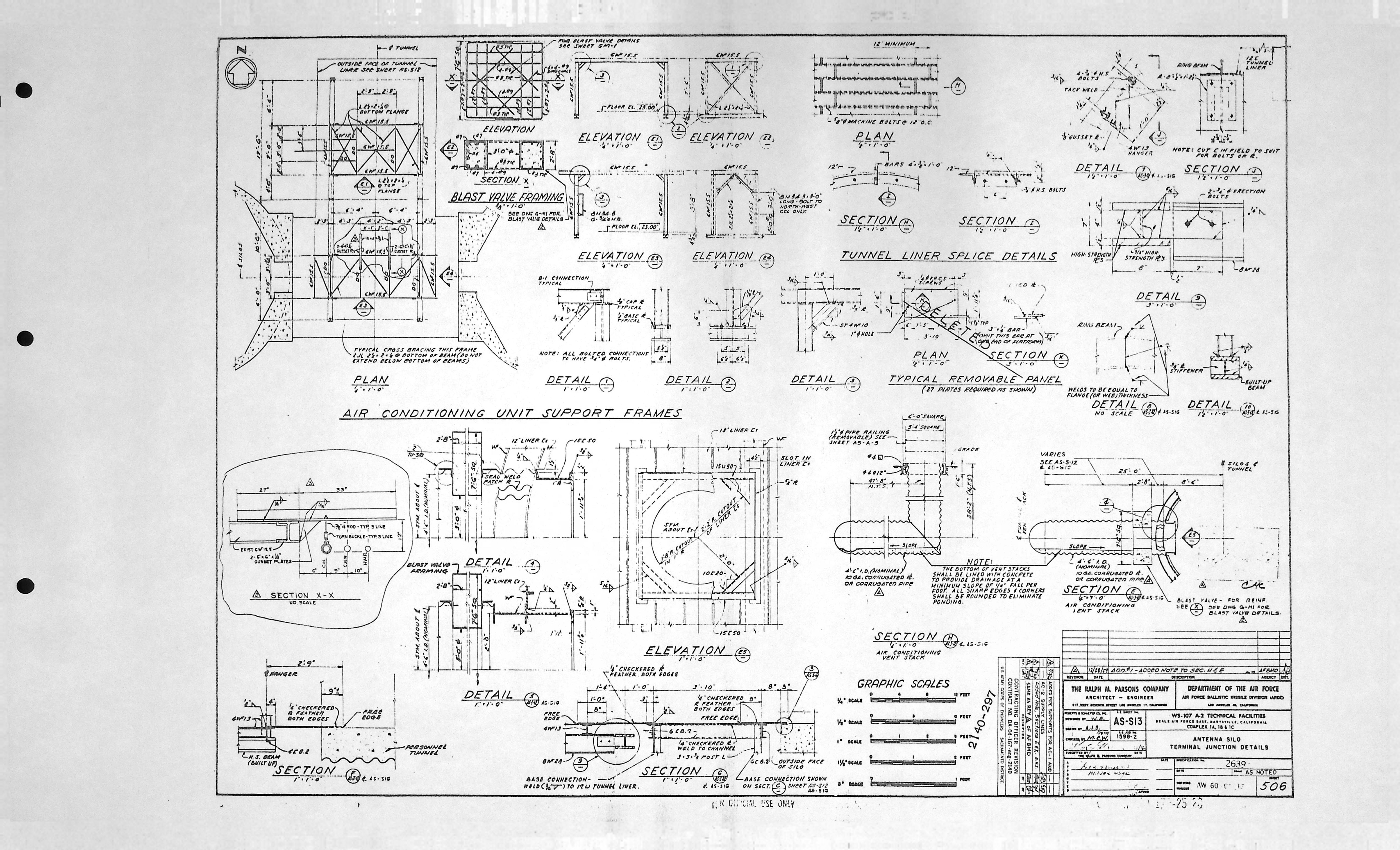
| AS-S13 | TERMINAL JUNCTION DETAILS |
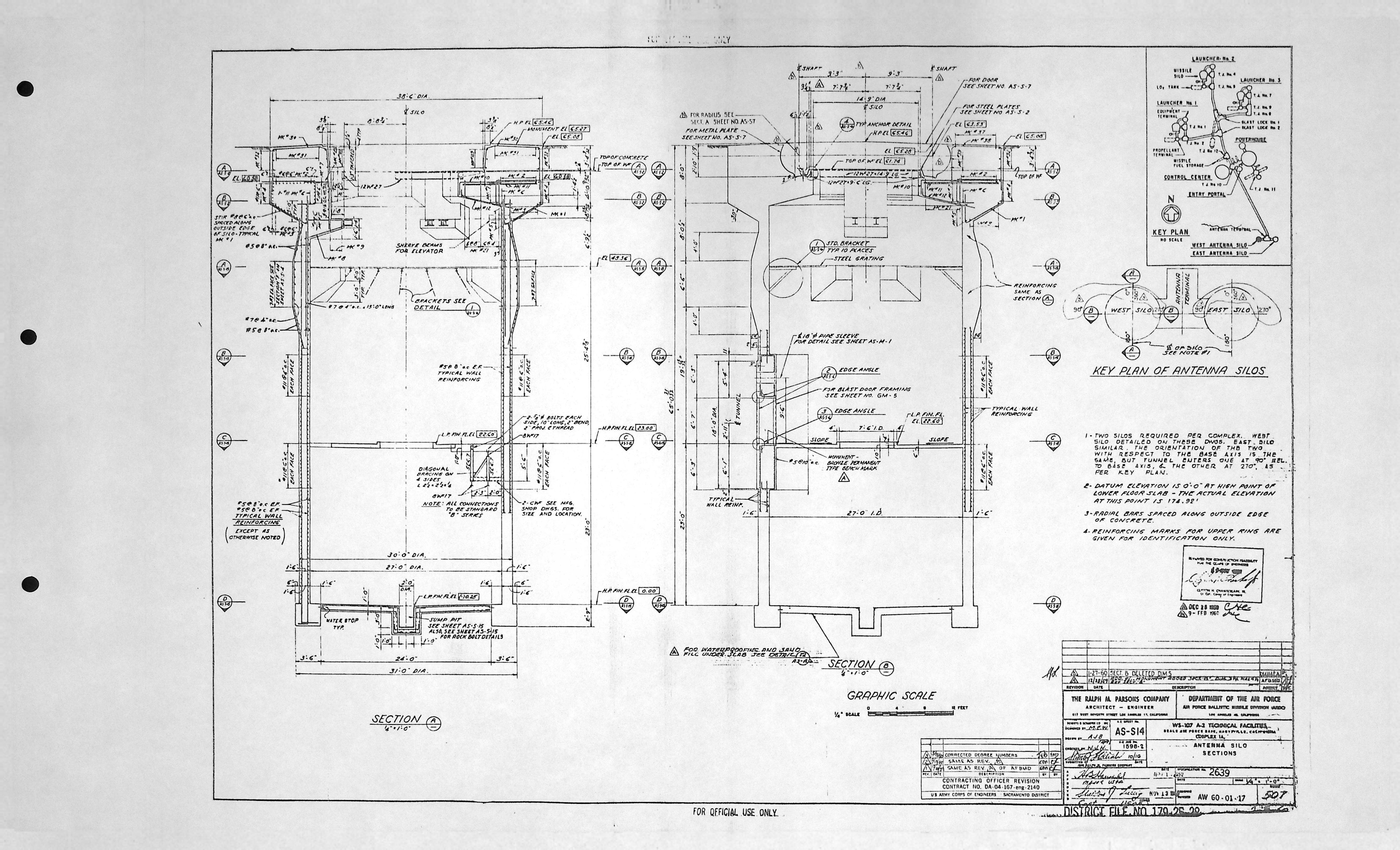
| AS-S14 | SECTIONS |
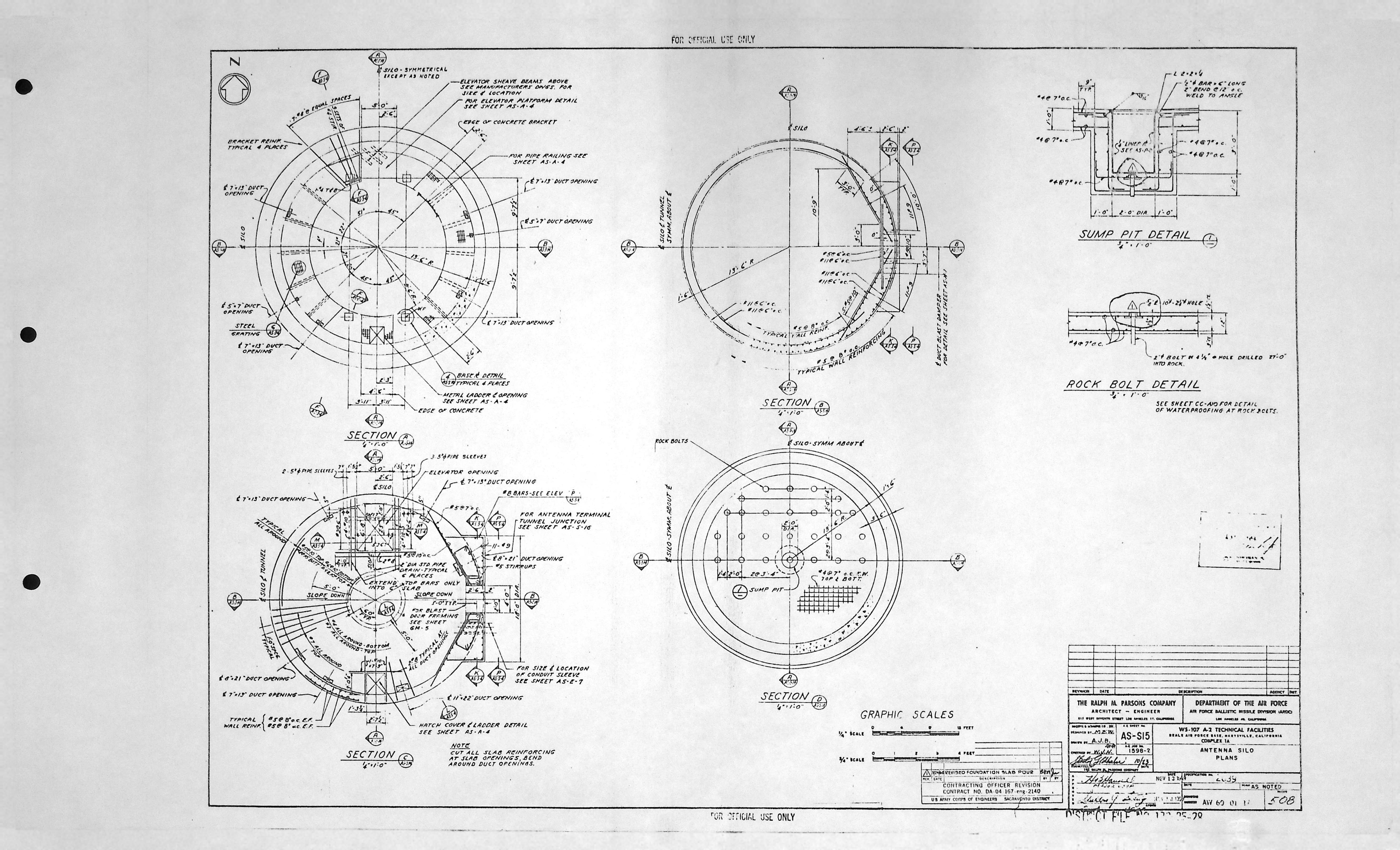
| AS-S15 | PLANS |
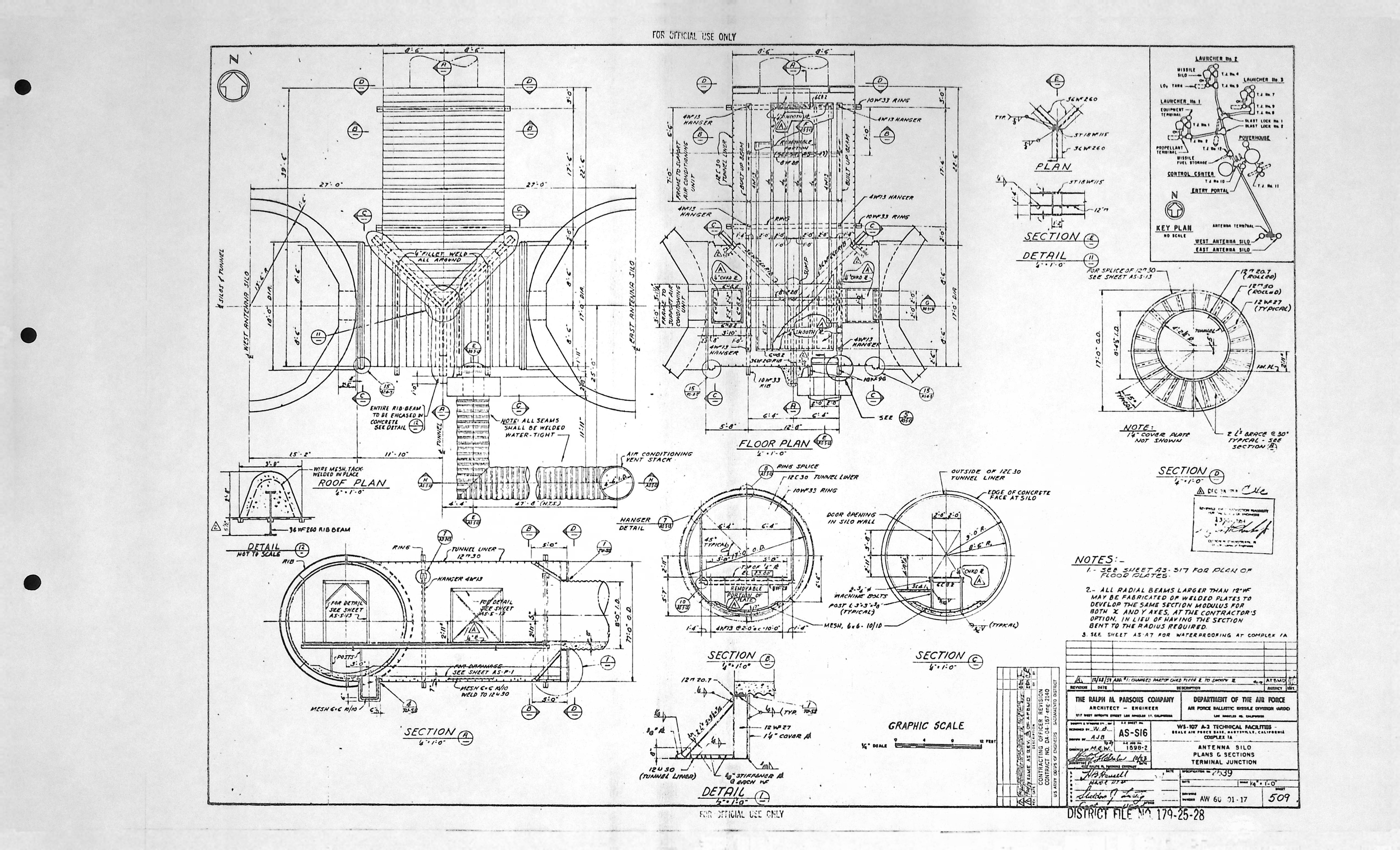
| AS-S16 | PLANS & SECTIONS TERMINAL JUNCTION |
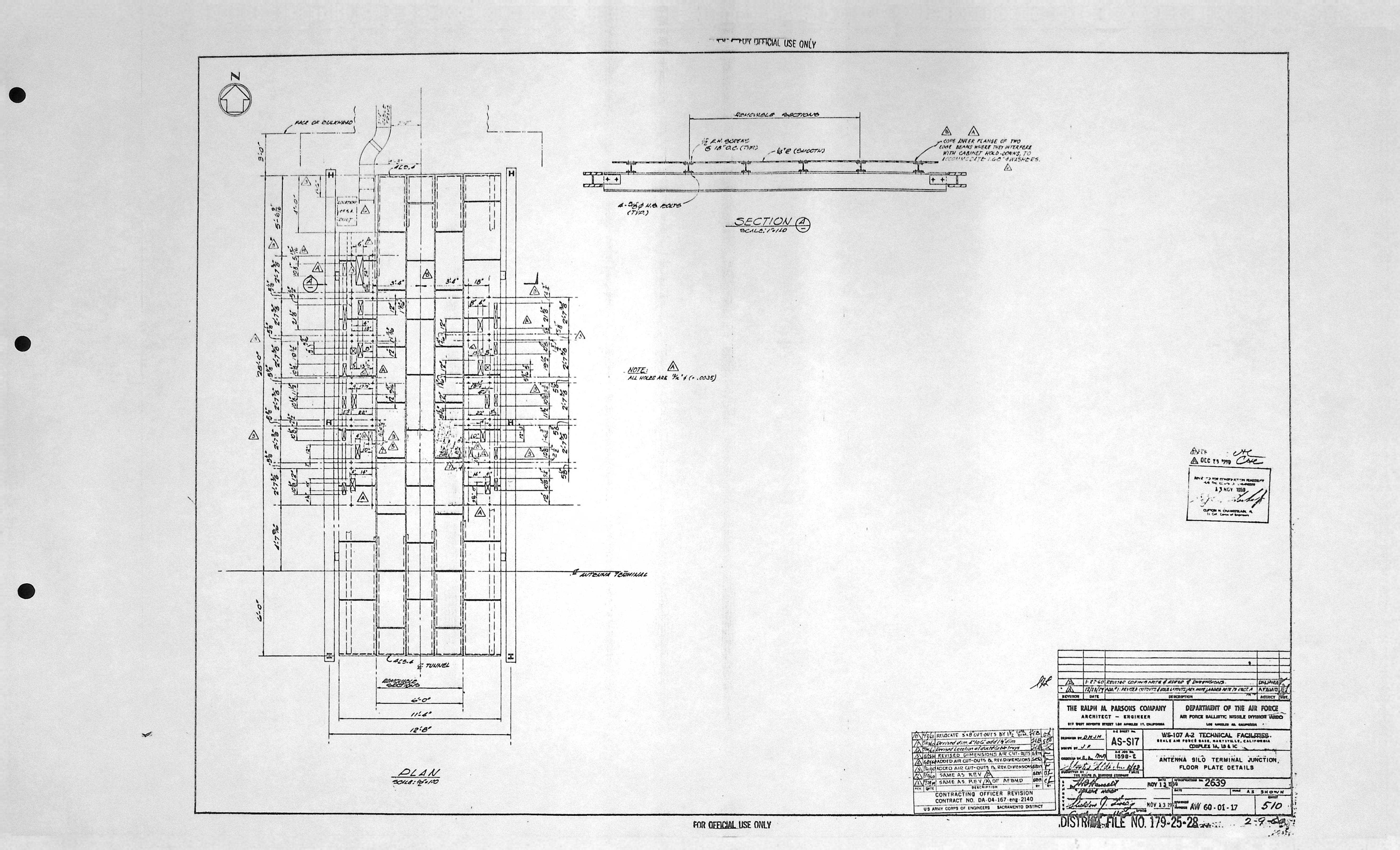
| AS-S17 | TERMINAL JUNCTION, FLOOR PLATE DETAILS |