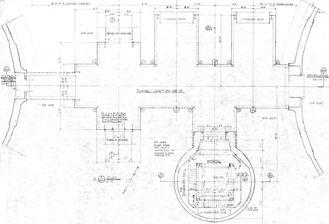
The nexus of the Titan I underground complex is this junction located just beyond the double blast doors at the bottom of the entry portal. Designated TJ no.10 (Tunnel Junction #10) by the engineers, this
complex steel structure connects all the major sections of the complex to one another.
TJ #10 connects the Entry Portal, the Power House, the Launcher Tunnels, the Control Center, and the Antenna Tunnel
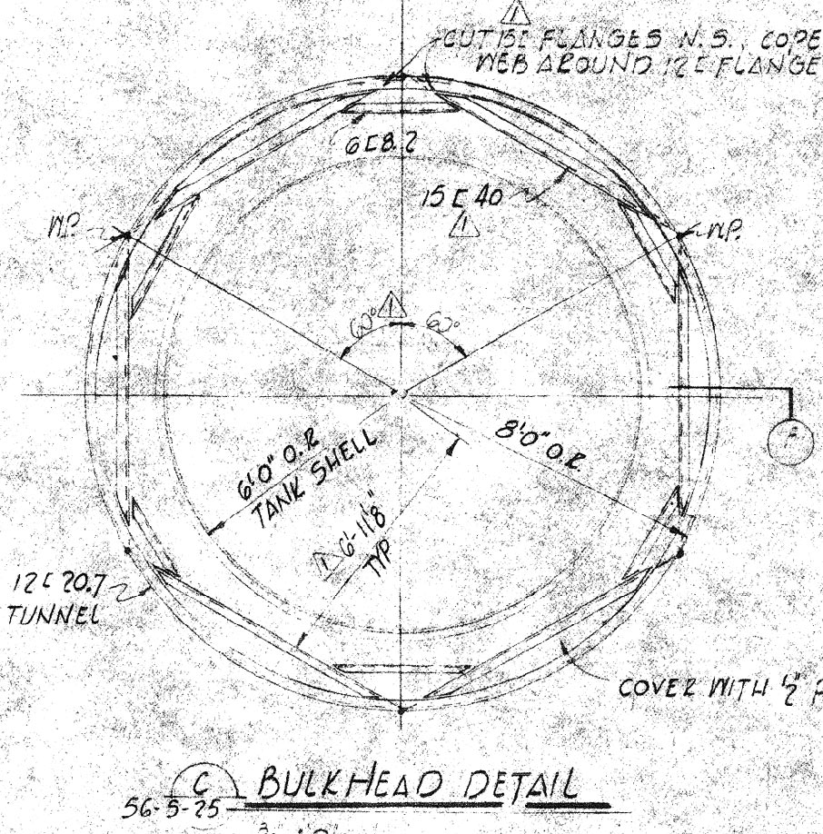
together in a web of tunnels that stretches out in all directions. Two raw water tanks also intersect in this area, interfacing it through two bulkheads.
The two raw ("raw" meaning not processed or de-mineralized) water tanks join the main junction directly across from the portal entrance. Each tank holds approximately 33,000 gallons, is
12 feet in diameter and 33 feet long. Water from these tanks served the equipment throughout the complex and the fire water and deluge systems in the missile silos. Water-based fire suppression in the silos could command a draw of
over 500 gallons per minute to an individual silo.
|

Detail
of the raw water tank bulkheads showing the distinctive hexagonal
reinforcement around the openings. Each tank held around 33,000
gallons of untreated water (hence, raw) supplied by 2 wells in
the power house.
|
The
most intricate of all the tunnel junctions, this was arguably the greatest
challenge faced by the steel workers on the project. Many of
the other disciplines involved in its fabrication and placement were
equally challenged by the emplacement of the section of tunnel, fitting
them to the surrounding structures and then backfilling to bury them.
|
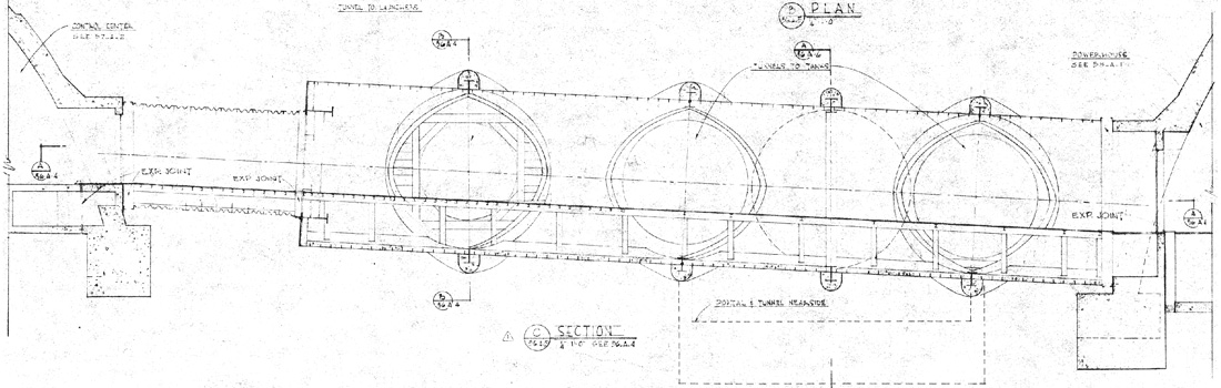
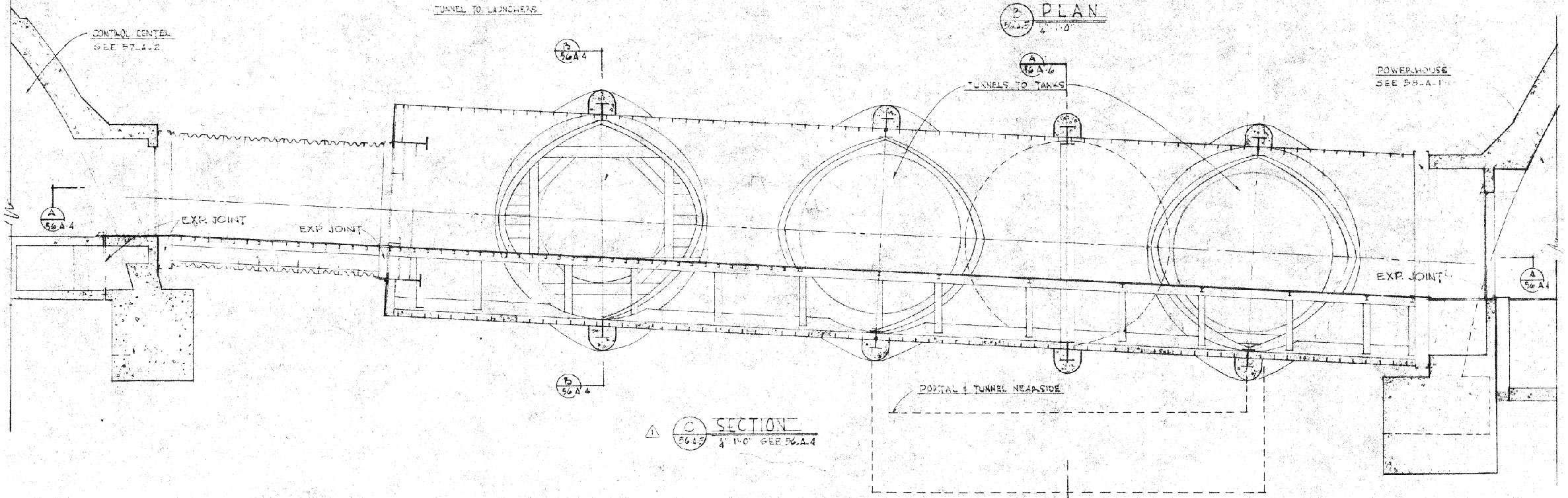
Drawing
showing a side view of TJ #10 along with the relative elevation of the
structure to the control center at left and the power house on the
right. This shows how all water entering this area is channeled to
the power house and into the pipe trenches where it could be collected
in sump wells and pumped out
to the surface.
|
Tunnel Junction #10 is a hollow steel structure comprised of
"curved channel bolted together and reinforced with heavy structural I-beams welded together to form a yoke section. Junctions were water proofed
and piped before delivery to the site."*
These junctions were later bolted and welded together to form a continuous interconnecting tunnel with an inner diameter of
15 feet 6 inches and are constructed of 3 gauge plate
steel.
*
From Lowry Area History dated Sept. 29, 1958 - Dec. 16, 1961. Read
it here.
|
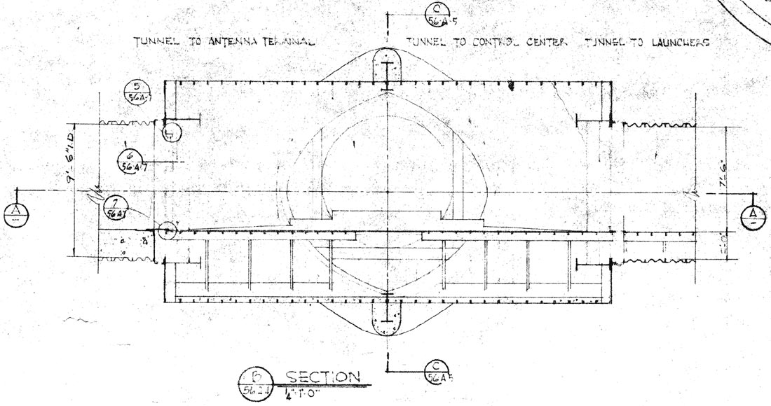
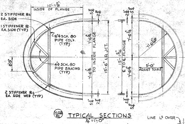
Drawing
showing a cross-sectional segment of the tunnel junction. The
antenna tunnel is on the left and the launcher tunnel on the
right. Directly ahead lies the control center entrance. This
drawing also shows some of the structure underneath the floor.
|
|

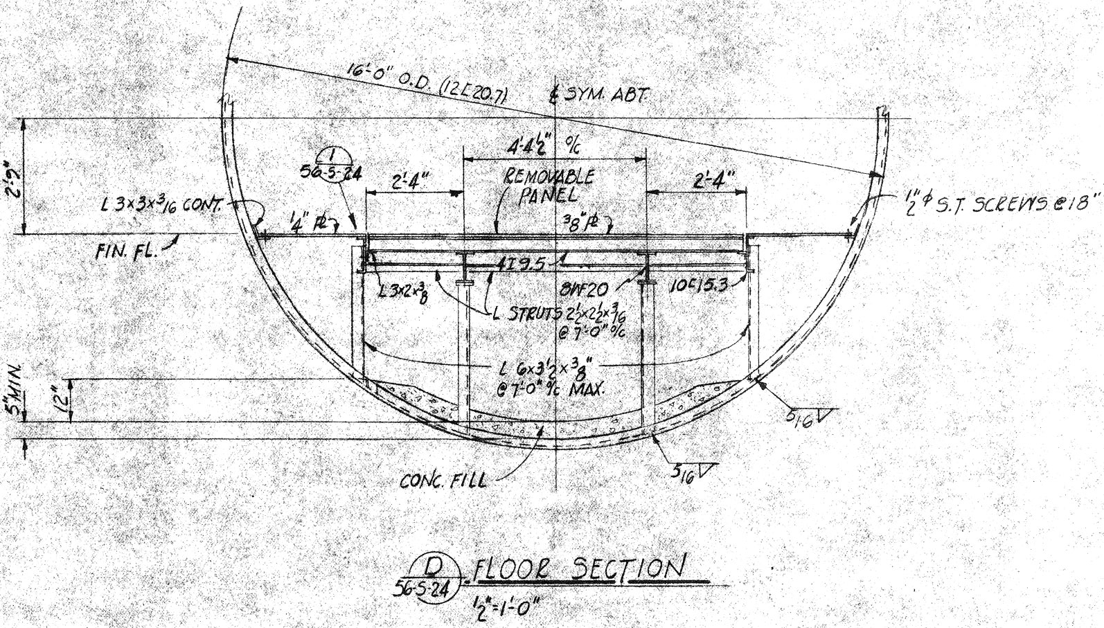
Detail
drawing showing a cross-section of the lower part of the junction just
outside the power house detailing the under floor structure and removable
floor panels. The bottom of the junction is finished with about 5
inches of concrete for better drainage.
|
Personnel tunnels consisting of the standard 9 foot 6 inch corrugated type connect the larger tunnel junction to the other neighboring structures. The interfaces of the smaller tunnels to the tunnel
junction are made by neoprene or rubber water stop seals which not only provided protection from ground
water infiltration at the join, but also allow the two structures some movement without damage--up
to a point. Most of these seals held, but they could (and did, as
you'll read further down) fail with very expensive and disruptive
results.
|
Detail
of the yoke beams that support the intersection of the segments of the
tunnel junction. Beams like these made up the corners where
segments met at 90-degree angles. This drawing shows the
reinforcing yoke beams unique to TJ #10 which had additional support in
the form of columns consisting of welded 4 and 6 inch steel pipe.
None of the other tunnel junctions at the Lowry sites have this added
support and it appears that this feature was peculiar to the Lowry Titan
I sites and is not found outside Colorado.
|
From
TJ #10, a short tunnel leads into the control center door and long tunnels lead off to the launchers and to the antenna terminal; double doors lead to the power
house and the antenna tunnel. The tunnel leading to the launchers has no door for ventilation reasons which allows air from the launcher air facility to flow into the tunnel junction from the
launcher tunnels. An 8'x8' doorway with 2 heavy steel blast doors provides protection from both bomb blasts and physical intrusion and serves as the entrance to the tunnel junction.
The floor
here is comprised of anti-slip checkered steel plating secured to the underlying I-beam framework below.
Underneath the floor, piping to fill the raw water tanks runs from the well pumps in the power house and 12
inch conduits from the raw water tanks directly supply the fire water system in the launcher silos. Hot and cold domestic water lines, sump lines and waste lines join the larger pipes under the flooring in this very busy crawl space. Along the walls and ceiling of the junction, cable trays and numerous conduits conduct electrical and
other services via a stunning quantity of cables. Utility air lines, from small copper tubing to larger steel pipes, run in all directions controlling air vents, valves, temperature and other systems.
Pipes and conduit of all sizes from remote corners of the site join the astounding tangle of services that run
hidden underfoot between the many different and
distant parts of the Titan I complex.
|
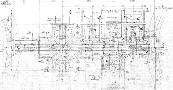
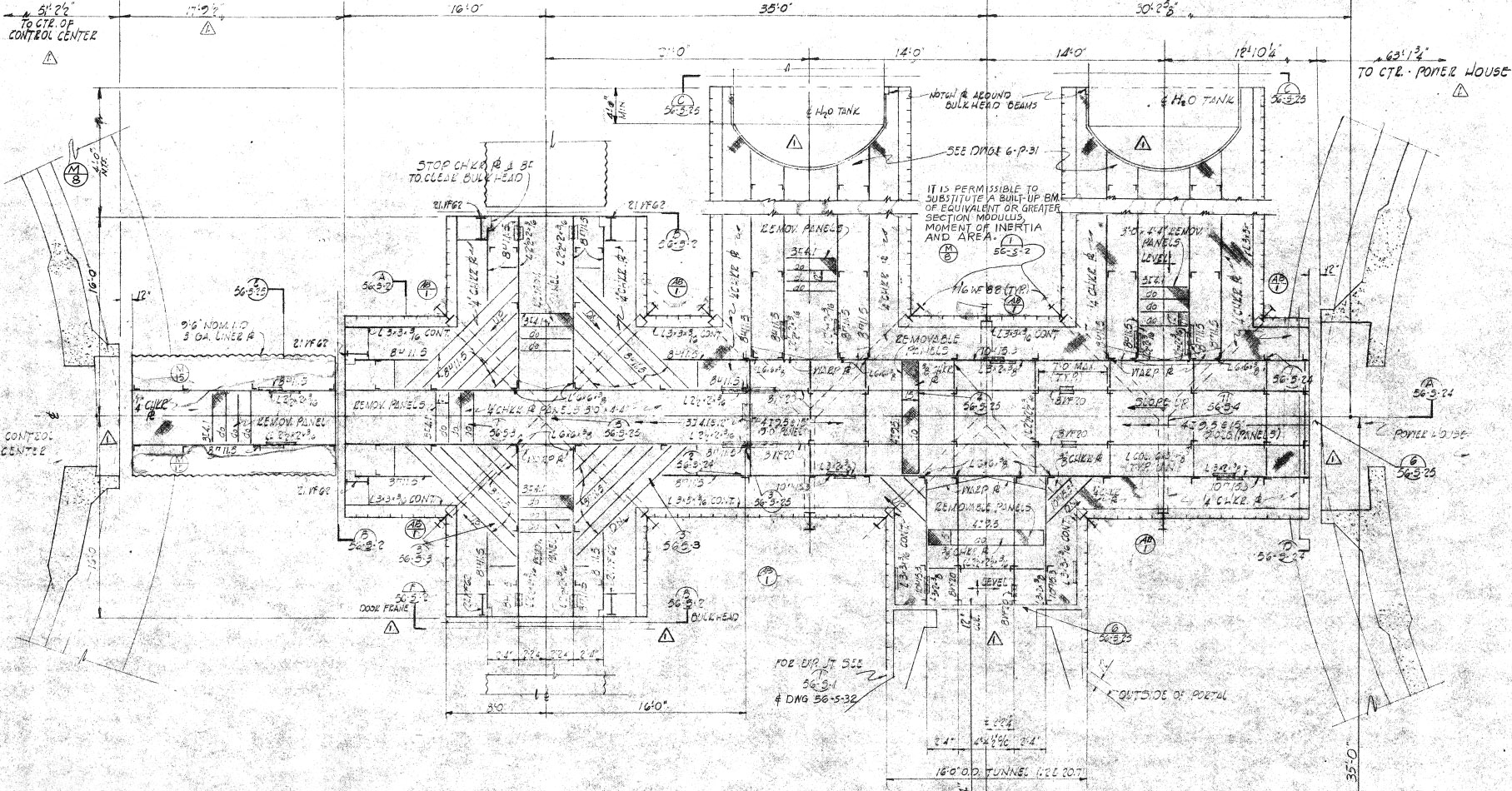
Drawing
showing greater structural detail of the tunnel junction and the
under-floor steel work as well as the way the yoke beams were positioned
to create the different joins between the tunnel sections.
|
Construction
Tunnel junction #10 was constructed in a modular fashion in large sections
at a location offsite. For the Lowry 724th and 725th missile
wings, the sections were fabricated at Buckley Air National Guard Base. The completed hollow sections were then outfitted with structural steel and
reinforcement and then plumbing was added before they were transported to the construction sites by
tractor-trailers and emplaced with cranes and heavy equipment.
Once in place the sections were welded and bolted together to form one large, complex section consisting of 5 branching tunnels and 2 bulkheads for water tanks. The interior
of the completed tunnel junction was 15 feet 6 inches in diameter and 95 feet 7-3/4 inches long from the
control center to the power house and 36 feet wide at the widest point where the raw water tanks enter the tunnel.
|
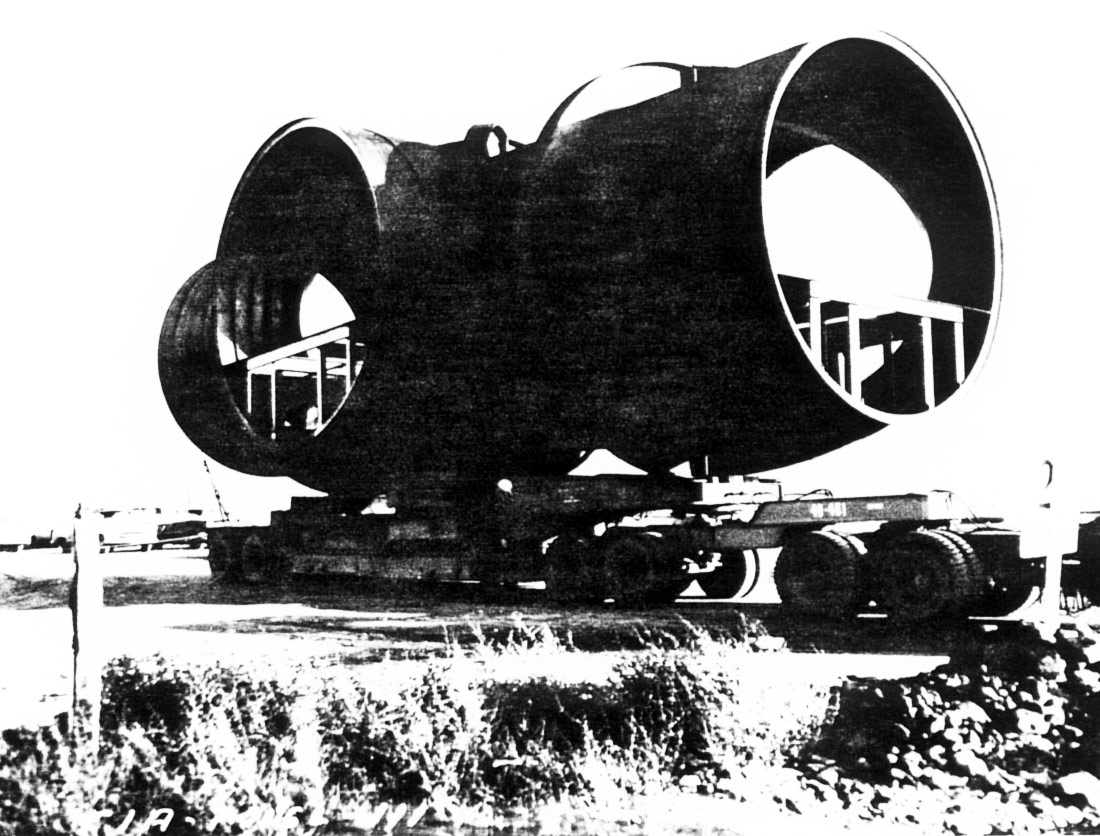
A
section of the tunnel junction prefabricated off-site and loaded on a
trailer for transport to the construction site. You can see the
floor structure which was installed before the section was emplaced and
bolted to its neighbors.
This
particular section appears to be the portion that branched directly off
from the entry portal. The opening on the left of the photo would
lead to the entry portal and the opening on the right led directly into
the power house. On the back side, two more openings would
accommodate the raw water tanks. Another large section like this
would continue off the left side to complete the junction with tunnels
to the antenna tunnel, control center and launcher tunnels.
Photo
courtesy of Fred Epler
|
The main tunnel junction was from an engineering standpoint a very difficult construction project to pull off. The majority of the Titan I complex was built by excavation and backfill-- that is, earth was
removed to the desired depth and then filled back in once construction was
complete. TJ #10 has more adjoining tunnel sections than any other part of the complex, meaning that great care was required so
that they would all meet correctly so they could be joined together.
|
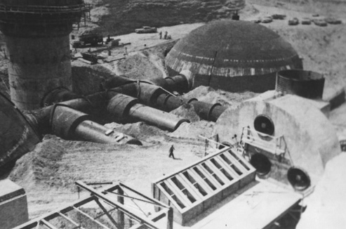
Construction
photo of a Lowry site showing the progress in the open-cut
excavation. This view looks over the partially-constructed power
house air intake facility at tunnel junction #10, the entry portal and
control center. You can see the junction is in place and mated to
the connecting tunnels. You can also see the yoke beams where they
cross over the exterior of the tunnel junction. The entire
structure was water-proofed and the yoke beams were further sealed and
protected by encasing them in concrete.
Photo
courtesy of Fred Epler
|
|
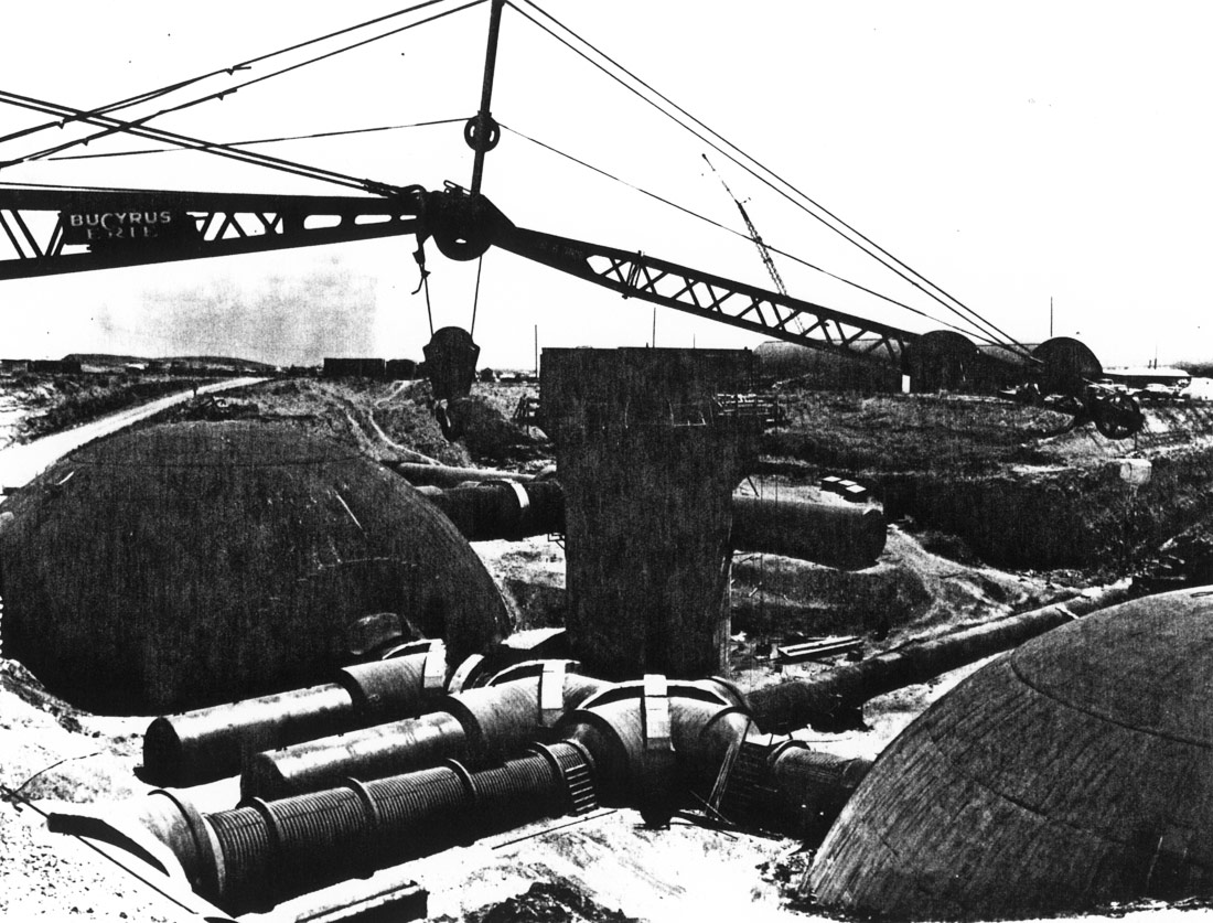
This
is a construction photo of one of the Ellsworth sites. The power
house is on the left and the control center is on the right with the
entry portal in the middle. The yoke beams have been reinforced
with concrete and backfill of the area may be ready to begin soon.
Note
the large Bucyrus-Erie crane in the foreground. Bucyrus steam
shovels were heavily employed in the digging of the Panama Canal and
their excavators and mining equipment are recognized around the world.
Photo
courtesy of Fred Epler
|
Once the placement and welding/bolting of the individual pieces of the junction was accomplished, difficulties arose from settling of the different adjoining tunnel sections.
Over time, this settling caused separation and
damage to some of the the rubber water stop seals at the joins between the tunnels and the
junction. Since the complexes were to be completely buried, infiltration by water in most locations was a fact of
life and in some it was a tremendous problem. One site in particular
(Larson 568-C near Quincy Washington) had grave difficulties when a failed water stop seal resulted in flooding at a rate of 20,000 gallons per
hour!*
*
Per U.S. Army Corps of Engineers report dated Sept. 28, 1962. Read
it here.
When backfilling around construction was begun, more settling occurred and the enormous weight of the soil caused more problems and warped tunnel sections out of shape. The 5 tunnels leading from TJ #10
were a constant source of headaches for contractors resulting in delays and cost overruns.
The
next section takes a much closer look at tunnel junction #10 at several
different sites and sheds light on how they look after their decades of
abandonment. You'll see that some sites have fared far better than
others!
Click the link below to continue investigating TJ #10
or go to the Main
Map to explore elsewhere.
Tunnel
Junction #10 Part II

|
Contact
| Site Map | Links |
Hosted by
InfoBunker