The
antenna silos are two cylindrical concrete structures, 65 feet deep
and 27 feet in diameter with a floor at the personnel access level
approximately 42 feet below grade and a lower service level at the
bottom. The walls of the silos vary in thickness near the cap
where they are heavily reinforced both to withstand blast forces as
well as internal loads from support structures for the door rams and
antenna assembly. Below these reinforced sections the walls are
15 inches thick with heavy steel reinforcement.
The
lower level contains an access ladder and lighting along with a sump
well and sump pump to purge any water that may enter the
terminal. This lower area exists largely to accommodate the very
long (around 4 stories, or ~40 feet!) hydraulic cylinder running up
the very center of each silo upon which the guidance antennas are
raised to the surface.
|
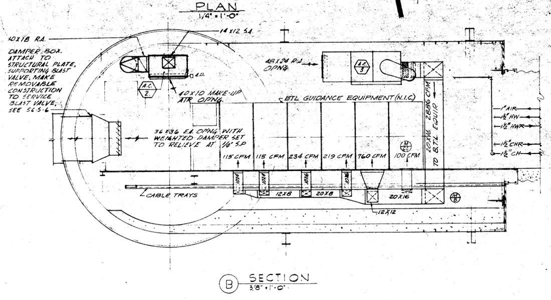
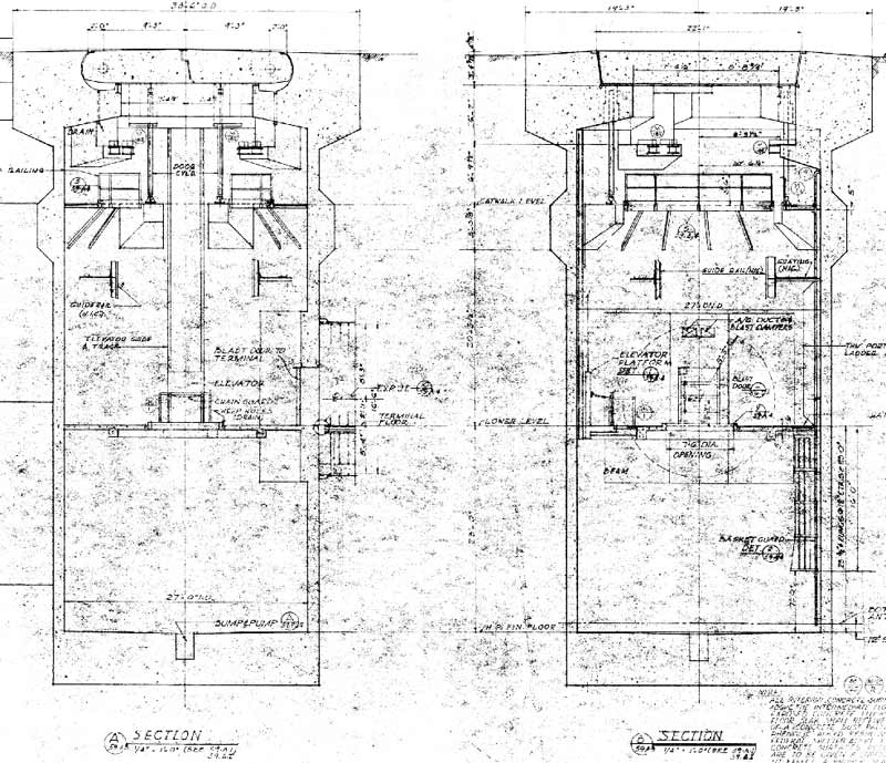
Terminal
room - Side aspect showing floor and HVAC layout. This structure
mated with the vertical antenna silos and antenna tunnel to interconnect
the three areas.
|
|
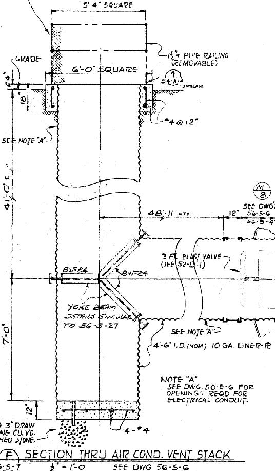
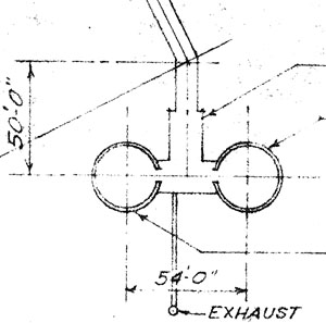
Antenna
terminal exhaust vent stack - Side aspect
|
The
silos are protected by two doors about 3 foot 9 inches thick with an
embedded ethylene glycol system to provide radiant heat to prevent
snow and ice from accumulating on the doors and hindering their
operation.
|
Antenna
silos - Side aspect
|
The
antenna terminal housed support equipment and controls for the silo
doors and antennas as well as racks of equipment, guidance systems and
heating, ventilating and air conditioning systems for the
terminal, silos and equipment racks.
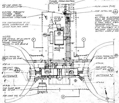
Heating
and cooling units were housed on an upper platform and ductwork was
routed under the floor and up through the bottom of each equipment
cabinet to provide cooling. Ventilation ducting supplied to the
antenna silos has special butterfly-type blast valves to prevent a
blast entering the terminal when the silo doors are open.
|
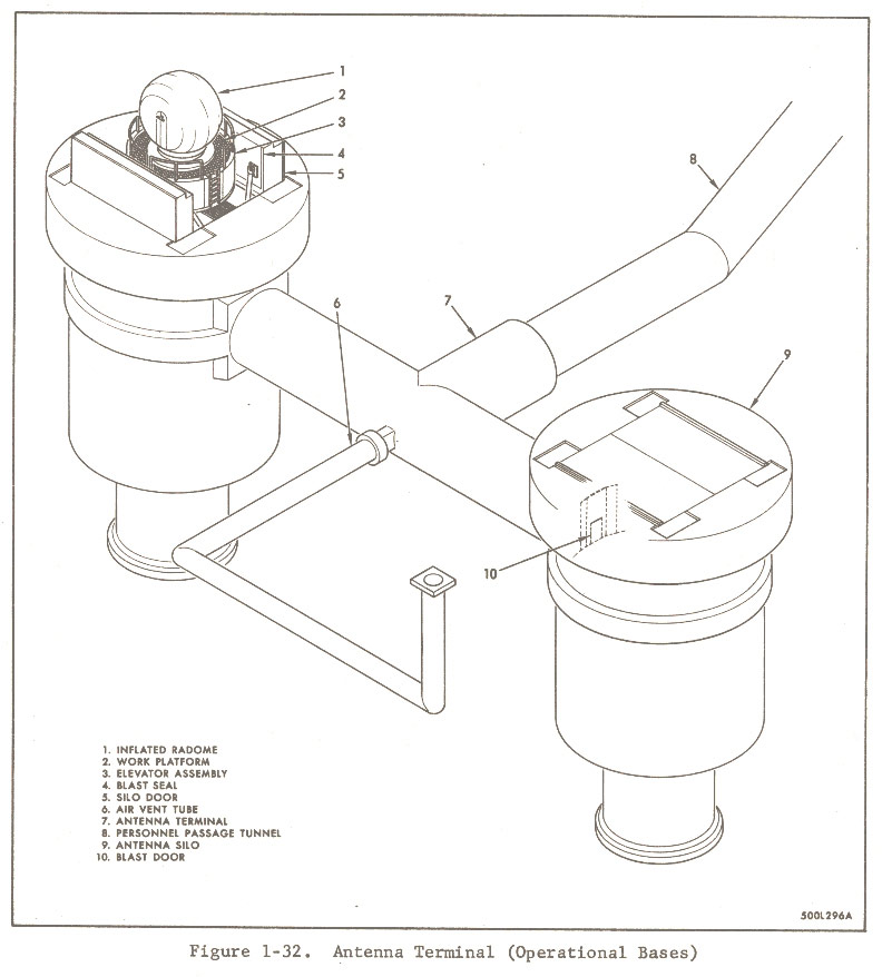
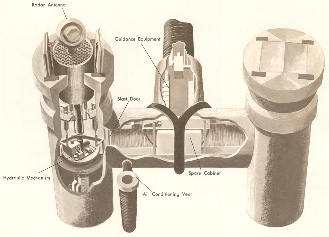
Isometric
diagram of antenna terminal
Note
that this diagram bears many structural deviations from the
"As-built" operational complexes. Two examples shown
here are the smaller bottom sections of the silos and the extra
convolution in the exhaust stack. These were not present in the
Lowry Titan I bases.
|
|
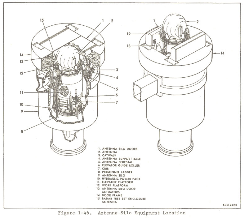
Isometric
Cutaway of Antenna Silo in the lowered and raised positions
|
The
twin antenna silos house the radar dome antennas for tracking and guiding the missile along
its trajectory. There were 2 antennas to provide redundancy in
case of failure since without a guidance antenna the entire site could
be rendered useless without a means to control the missiles. As
an added measure of redundancy the Titan I system had the ability to "hand off" guidance and control of
any missile at any complex in the squadron or wing to allow it to be
guided
remotely.
That
is, if critical failures of say, the guidance antennas of one site
brought it off alert, any other site could use their own Control
Center and antennas to launch and guide the missile so they would not
be left dead in the water.
|
Cutaway
of the antenna terminal - This is a pretty close representation of the
actual Lowry bases' construction though the details are a bit rough.
|
Each silo is
protected by a set of massive two-leaf concrete doors which would
shield the antennas in their hardened state. The antennas
themselves consist of a radome radio dish enclosed within an inflatable canvas
dome which is expanded by a blower (squirrel cage type fan) when in use.
When
needed, an antenna would be raised to the surface hydraulically on its
platform. Only one antenna would be raised at any one time to
prevent both being disabled in an attack. The antenna was raised
on a single hydraulic ram that extended over 20 feet below the floor
level of the silo. The antenna itself and much of it's support
equipment was suspended on a hanging platform that could move and sway to
suppress shock. Hung from 6 six incredibly strong cables with
massive shock-absorbing springs, the whole antenna assembly was
designed to shake and bob a tremendous amount without sustaining damage.
Once
the antenna was raised to the surface, it was locked solidly in place
by a hydraulic mechanism to ensure its accuracy in tracking and
guiding the missiles. When guidance operations are in progress,
a moving radio antenna will simply not do.
|
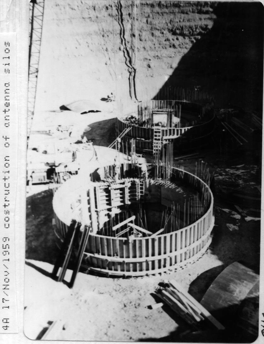
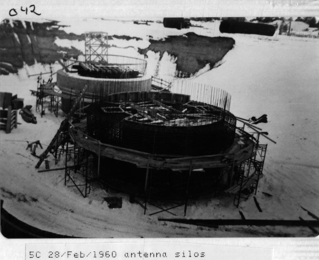
Construction
photo of antenna silos showing the first few pours completed and forms in
place. Note the curved section of form resting at the lower right
and the crane boom visible at the upper left. The crane was used
to position the massive forms and for other heavy lifting.
Photo
courtesy of Fred Epler
|
Construction
The
antenna terminals were constructed using the same method as the rest
of the more shallow silo-type structures like the equipment terminals,
entry portal and propellant terminals. First the whole area was
excavated to a depth of about 48 feet and once the proper depth and
leveling was achieved, the base slab was poured and the remaining
structure built using successive concrete pours and reinforcement
until complete.
Once
a section of concrete was cured and sealed and any interconnecting
tunnels and structures were complete and water-proof expansion joints
were installed, the entire construction was re-buried using the
excavated earth which was then laboriously compacted to prevent
(insofar as was possible-- see the antenna
tunnel section for details on
the perils of backfilling) settling and movement of the soil and
underground structures-- a very undesirable outcome.
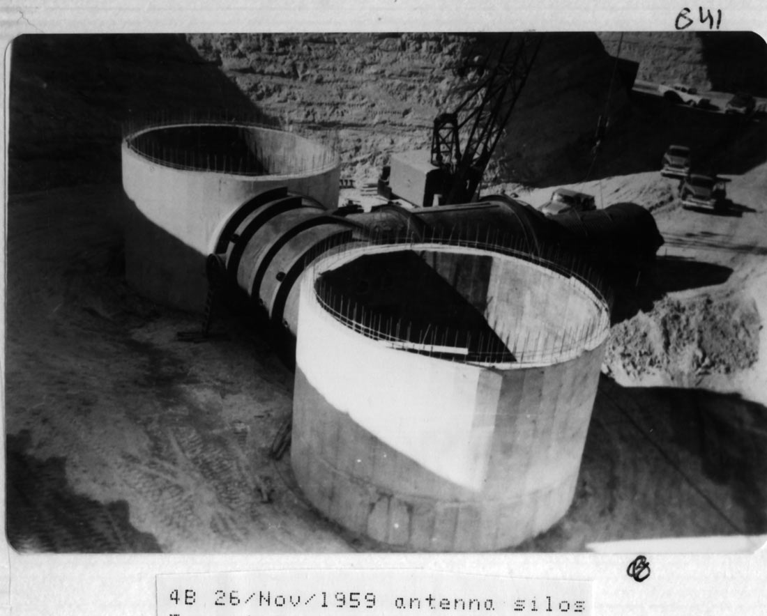
Backfill
was added in a step-wise fashion in most cases where soil was added
and compacted around the newest completed section. The following
photo shows the silos already buried to a depth of about 23 feet.
|
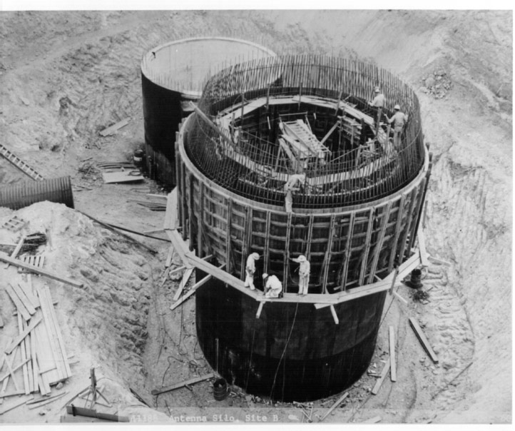
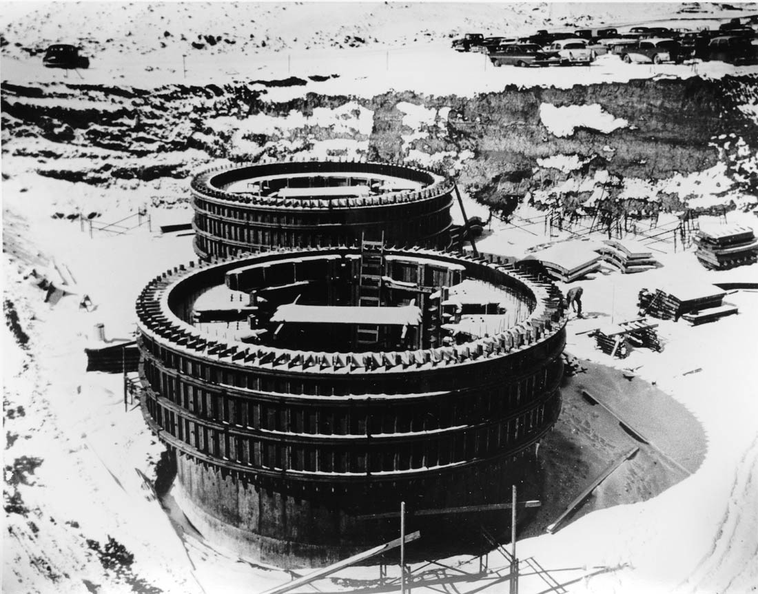
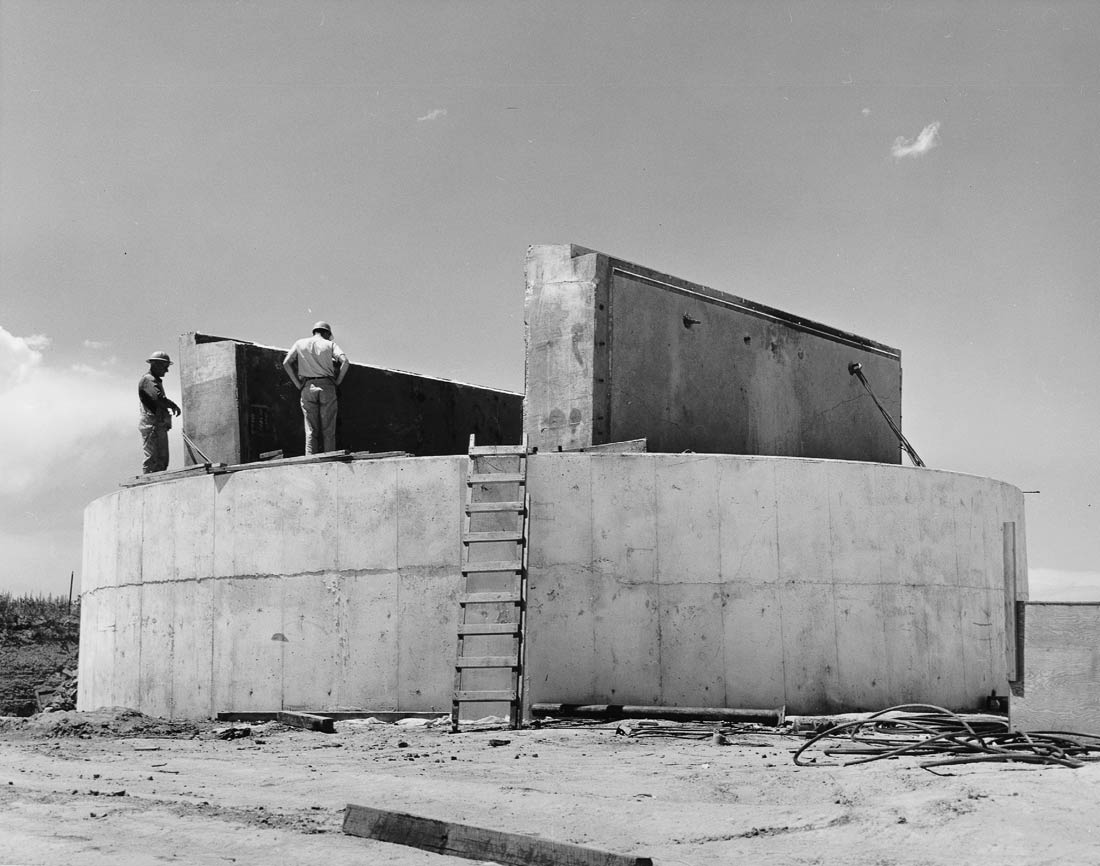
Making
progress - the antenna silos are really taking shape as workers ready
the forms for the next pour. Notice the tunnel liner jutting into
the photo on the left. Later this liner will be mated to the
larger terminal structure and sealed.
|
The
walls were built up using forms in about 8 foot sections to encase
steel reinforcing bars in between. When a section was properly
set, the next section was started, re-bar first, and then the forms
moved to enclose the next pour. In this way the structure grew
upward until the final pour was ready: the doors.
|
Progressing
nicely - this shot of site 724-B shows the terminal structure mated to
the silos and the backfill completed up to level of the personnel
tunnel. There are about 25 feet more to be added to each silo at
this point. The remaining pours will be much thicker and add
structure to support the antenna platforms and rams for the doors.
Photo
courtesy of Fred Epler
|
|
Cold
Colorado weather hinders concrete work at 725-C. Silo A's cap
appears to be complete in this photo (no doors yet, however) but silo B
has at least 1 or 2 more pours before the doors can be added.
Frigid
weather posed major challenges for contractors in states with more
inclement winter weather such as Colorado where concrete had to be
heated prior to pouring and then warmed with diesel heaters while it set to prevent
freezing.
Photo
courtesy of Fred Epler
|
|
Forms
for the final cap pours are in place awaiting either warmer weather or
further preparations for winter concrete work.
|
The
silo doors were rather interesting in their construction. Each
were comprised of a dense mesh of heavy steel reinforcing bars and
high-strength concrete and weighed around 100 tons. As such,
they were not something that could be constructed off-site and
installed in the antenna silos. Instead, each was constructed in
place, right there on top of the silos.
The
massive, solid steel hinge pins and trunnion assemblies (hinge
bearings) were installed, rebar was measured, cut, bent, placed and
welded*
and forms were constructed and positioned on the silo caps. This
also included the installation of piping that snaked back and forth
inside the doors to facilitate radiant heating for snow and ice
removal. Once the forms were complete, concrete was poured right
around the hinge pins, rebar, piping and all.
After
the forms were removed, the two separate leaves of the door were
broken free using hydraulic jacks and opened. After the doors
were opened, the four hydraulic rams were installed and tested.
*In
typical construction, most
steel reinforcement is constructed into a latticework using wire to
tie the bars together. This is fine for most applications, but
the specifications for the Titan I complex called for "continuous
reinforcement" which meant that rebar was welded together instead
of just tied with wire, adding a far greater strength to the concrete
pours as a single large mass.
|
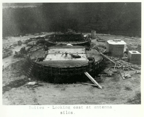
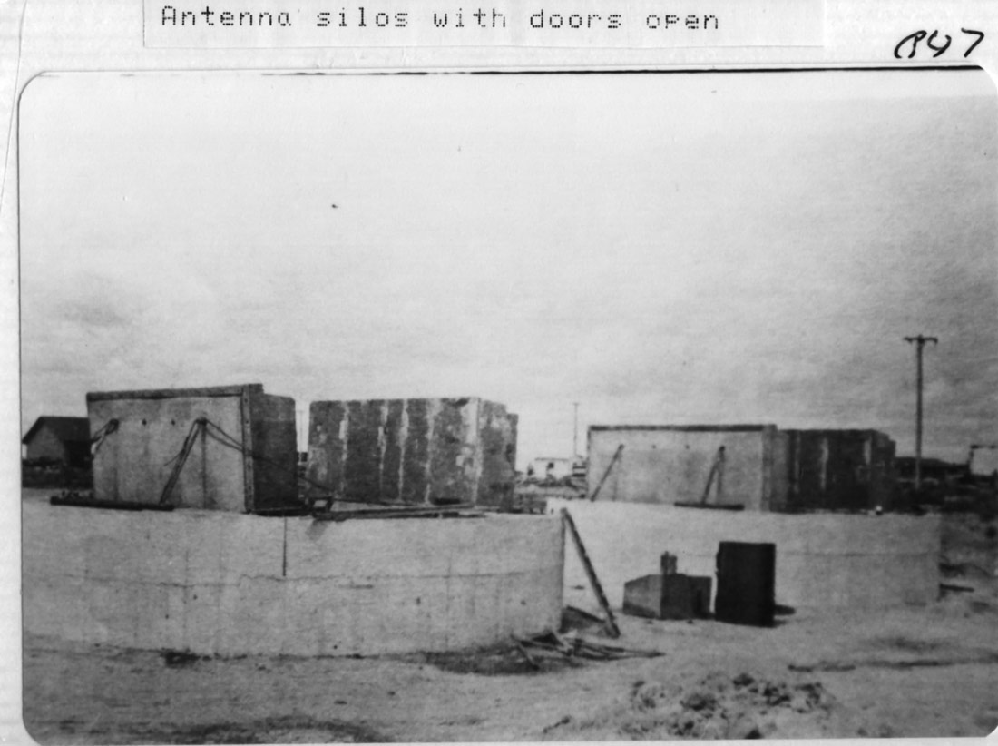
Completed
silos with one set of doors poured. Next, hinge plates will be
installed at the corners of the doors.
|
|
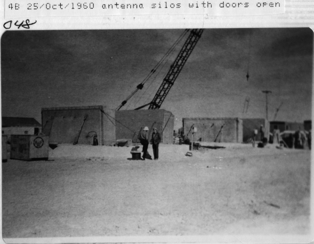
The
silo doors are complete and opened and awaiting installation of the
hydraulic rams while construction work continues inside. Most of
the backfill operation is also complete in this area.
Photo
courtesy of Fred Epler
|
|
A
closer look: Still no rams on the doors and there's still some backfill
to be done at this site
Photo
courtesy of Fred Epler
|
|
Still
awaiting a closing mechanism, the doors are temporarily secured from
accidental closure by steel cables in this photo as work continues.
|
|
A
nearly completed silo with doors closed at Lowry 724-A
Photo
courtesy of Fred Epler
|
|
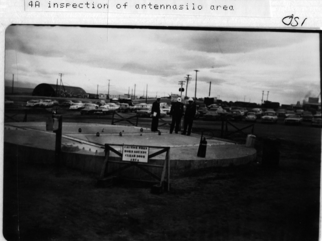
Silo
at 724-B with antenna installed and raised and door rams in place.
Notice the concrete structure in the lower center of the photo.
This is the seal chamber where purged sump water discharges from.
Photo
courtesy of Fred Epler
|
|
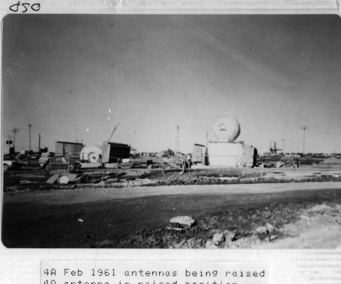
724-A
with silo B antenna raised and silo A on its way up. The rest of
the complex is still in the throes of construction in the background.
Photo
courtesy of Fred Epler
|
Here
you see the focus of the antenna terminal and in fact, the 2nd most
important part of a Titan I complex after the missile itself: The
Western Electric Missile Guidance Set AN/GRW-5. Evolved from
naval guidance systems, the AN/GRW-5 MGS consists of (in the context
of the Titan I weapon system) the guidance set itself, the antenna
protecting and elevating set-- the hardened silos and the hydraulic
platform that raises the antennas to the surface-- a testing and
checkout set to maintain, diagnose and exercise the system and ensure
proper function, a missile guidance computer set and missile-borne
guidance equipment on board each Titan I.
A
very complex system indeed, the antennas pictured here are like the
tip of the iceberg that is the complete Missile Guidance Set developed
by Bell Telephone Laboratories; a radio-inertial missile guidance and
tracking package representing, at the time, some of the very latest in technology
and miniaturization in solid state electronics.
|
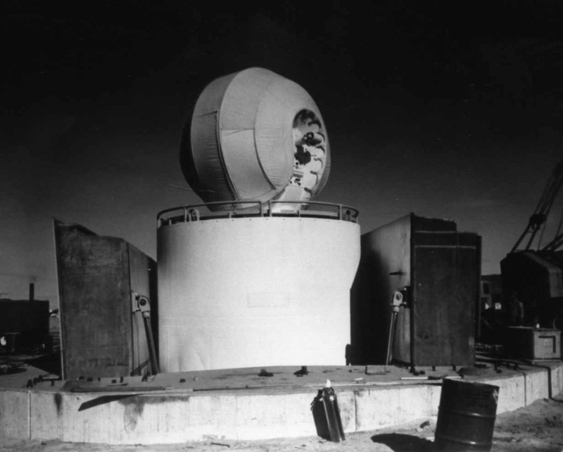
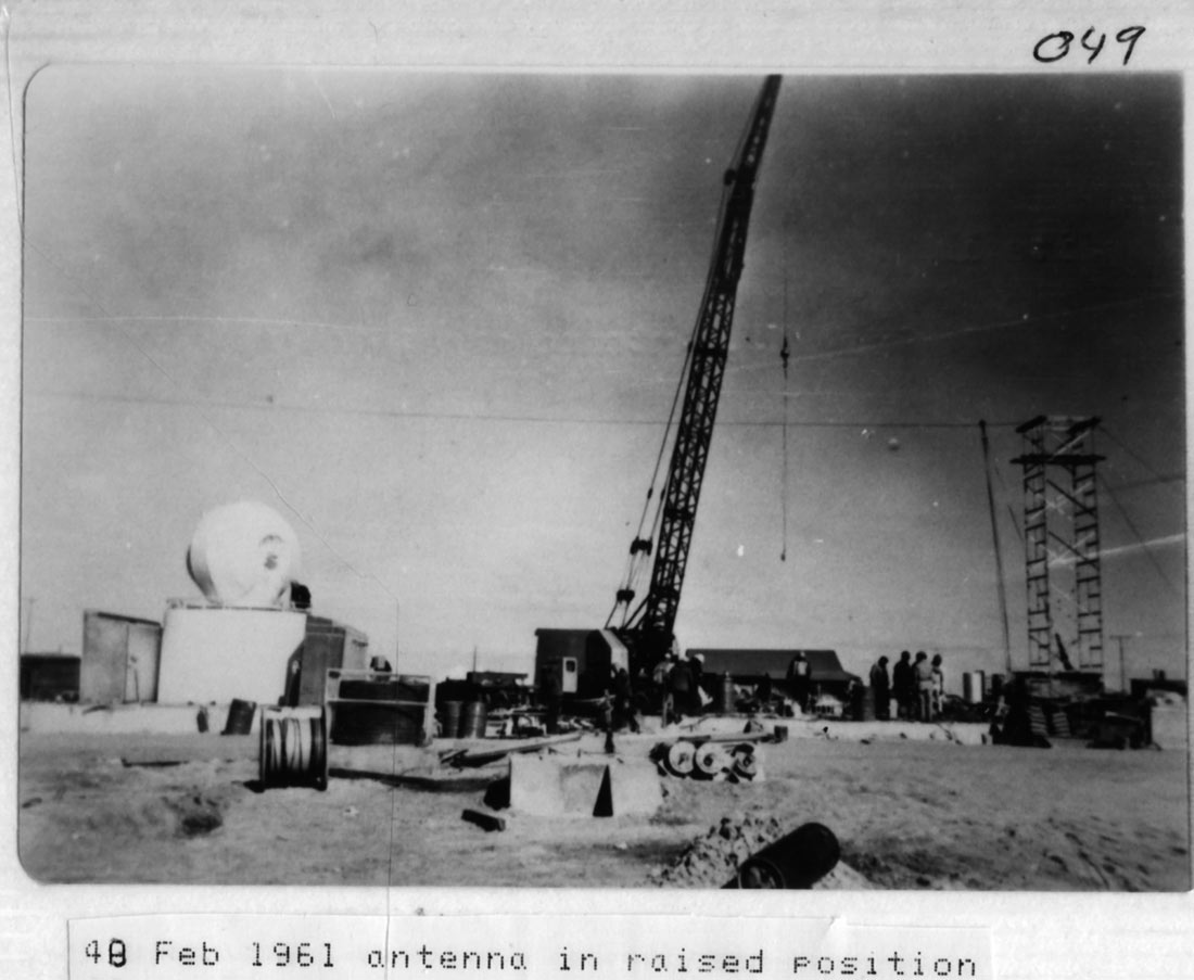
A
closer look at the raised antenna with its inflatable canvas
shroud. A small blower keeps the dome inflated during operation.
For safety, extendable railings ring the antenna platform for use during
maintenance.
|
|
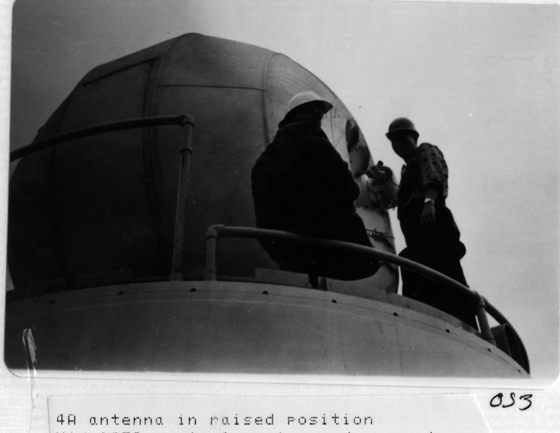
Inside
the radome antenna is a dish-shaped radar receiver/transmitter that
moved about the axes of azimuth and elevation to acquire and maintain
radio contact with the missile or ground-based test set.
|
|
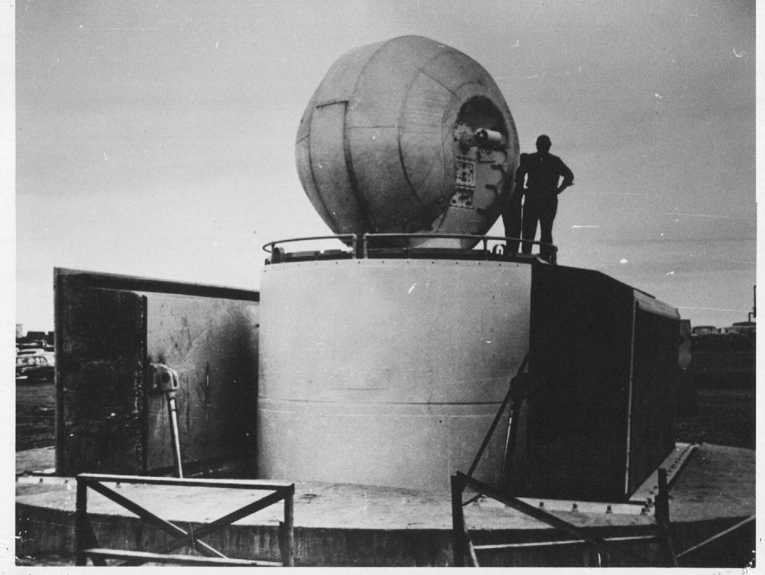
Unknown
persons at 724-A antenna platform, showing the inflatable dome.
Here you can see a section of railing raised in the "working"
position.
Photo
courtesy of Fred Epler
|