|
1999,
Lowry 724-C: My first visit to the catwalk level, I try to make sense of
what I'm seeing, unaware of the mysterious object I would discover
minutes later.
|
I
made my way carefully up the ladder and paused at a lower access
platform below the actual catwalk. This platform was flanked by
a retractable gangway that provides access to the antenna platform
while the antenna is in the silo and allowed for ease of maintenance
and repairs when the silo was "hard", or closed.
|
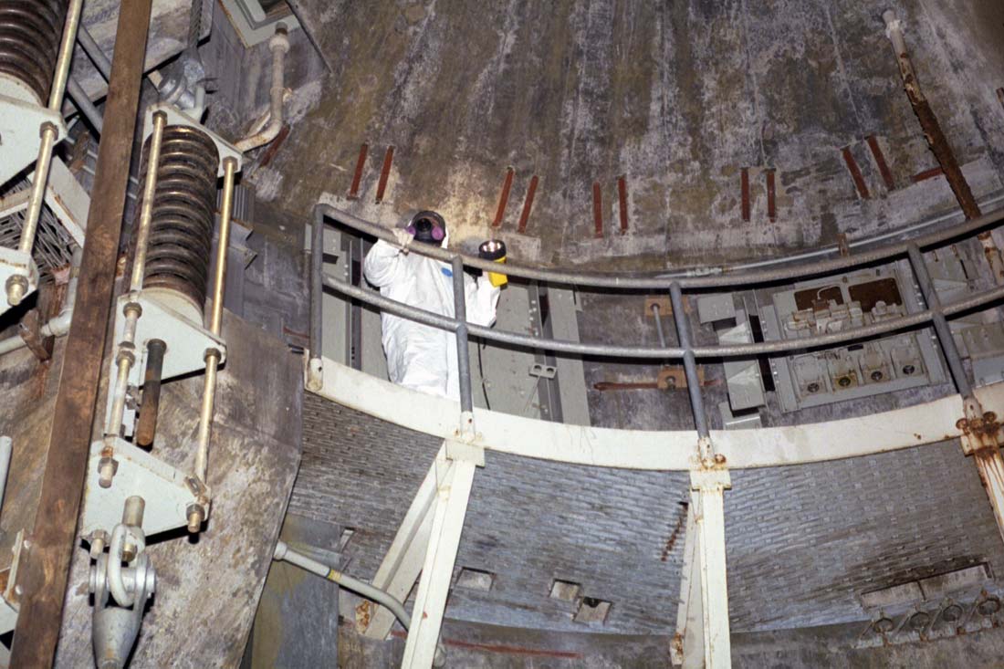
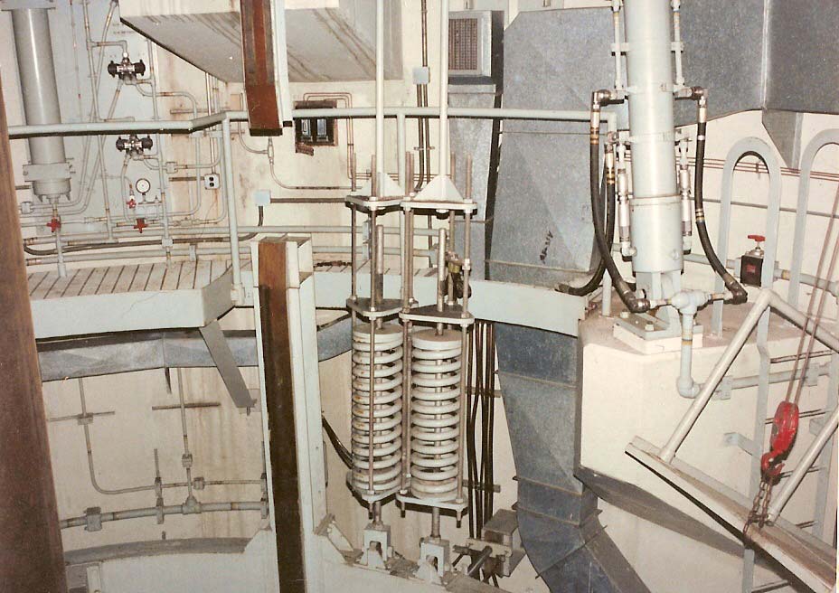
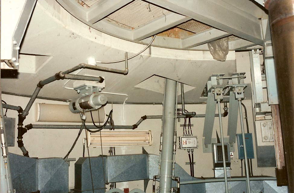
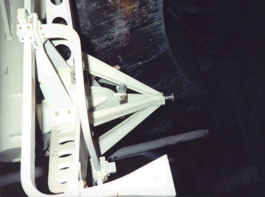
Circa
2002, Lowry 724-C: A small platform below the catwalk. On the left
you can see part of one of the big spring assemblies. Movement of
the spring was detected by the small switch contacting a rod at about 45
degrees. As the springs compressed or expanded, this movement was
detected by these small sensors.
|
From
the platform I got a good look at the spring mounts supporting the
entire antenna platform. There were 6 of these springs
supporting each antenna platform. As I marveled at the obvious
strength and durability of the whole construction, I found a laminated
tag affixed to the steel cable with a piece of wire. I took the
liberty of liberating that tag:
|
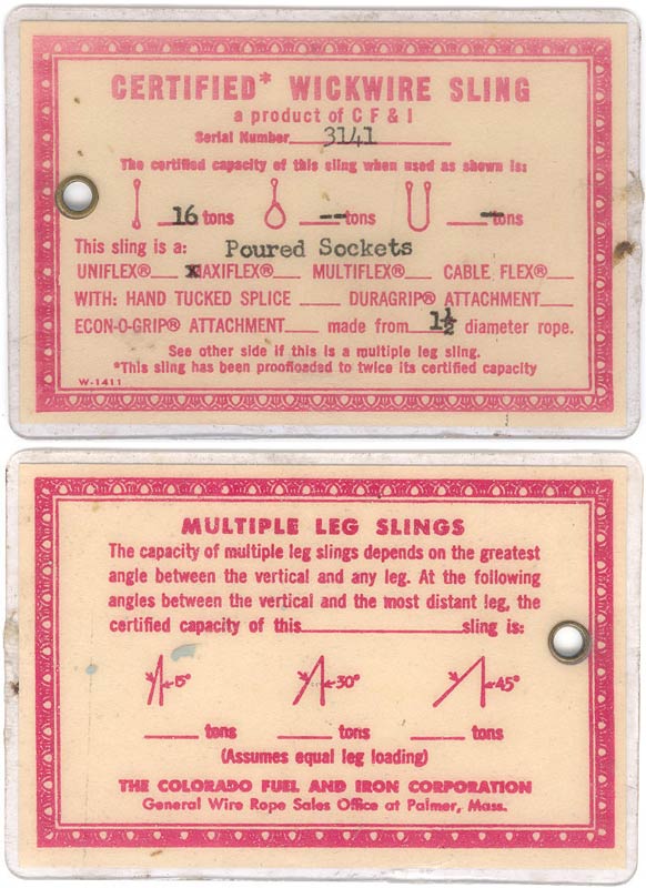
Certification
tag for the steel cable supporting the antenna platform. Some
pretty stout stuff I think you'll agree.
|
Looking
at this tag, it shows that the certified capacity of each of the 6
cables supporting the antenna platform was 16 tons each for a total
capacity of 96 tons! Further inspection reveals that these
cables were really capable of an absolute maximum of 192 tons or
more!
|
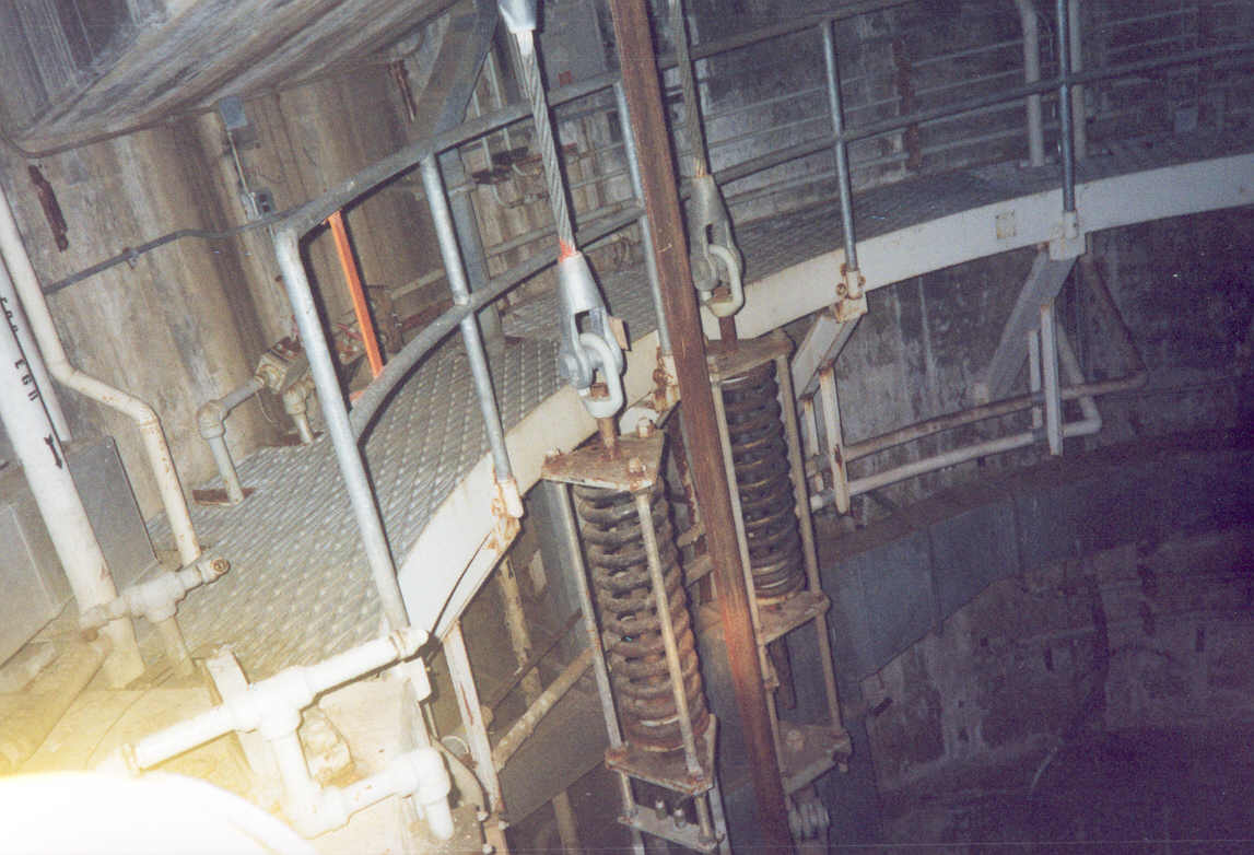
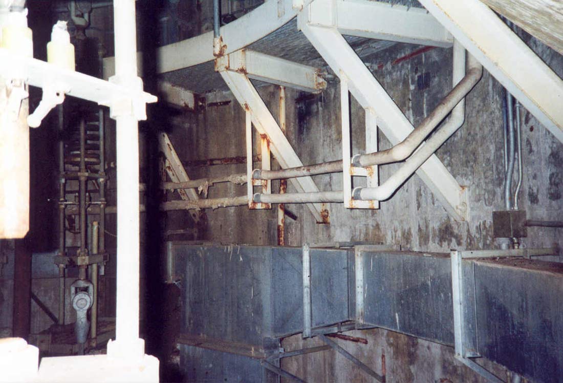
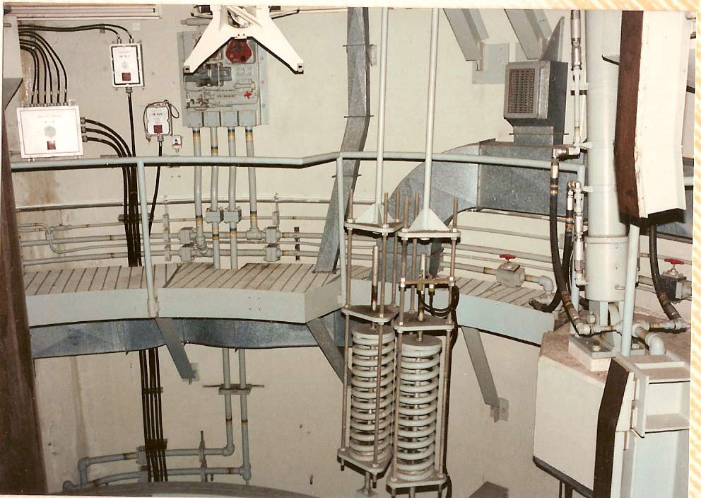
A
better view of the massive springs supporting the antenna. If you
look very closely you can see the tag pictured above still attached to
the cable near the top of the closest spring.
|
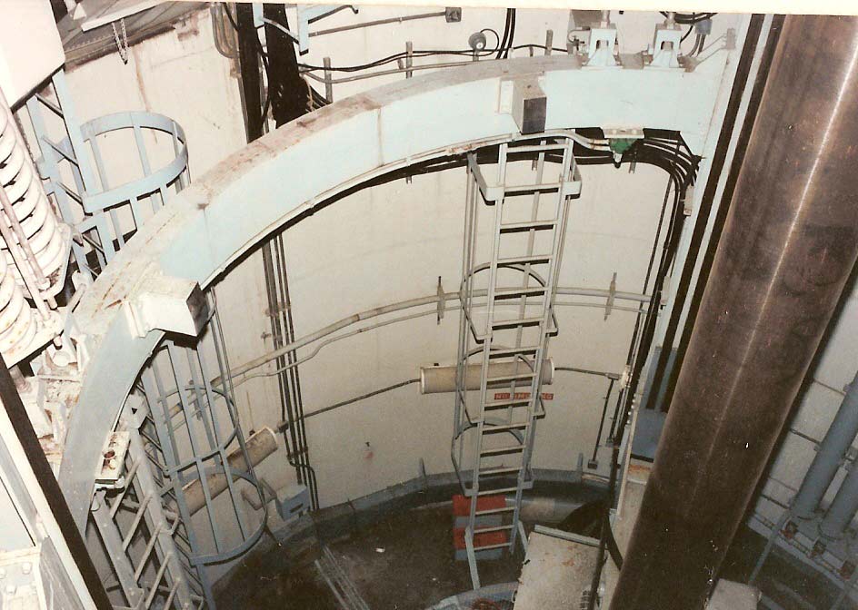
Climbing
up the last 10 feet or so, I arrived at the catwalk level of the
antenna silos. There were lots of pipes and other head-hazards
to look out for above and plenty of trip hazards protruding up from
below through the deck, making for moderate treachery.
Hydraulic
lines for the antenna up-locks and silo doors ran hither and yon along
the walls, sprouting from control panels and branching everywhere
competing with electrical conduit, heated glycol lines and other
plumbing for space along the silo walls.
|
1999,
Lowry 724-C: Gaps in the railings like this one were once protected by safety
chains and the presence of the antenna platform which had occupied the
empty space where now one could easily plummet some 25-30 feet to the
unforgiving floor below.
|
Dodging
these obstacles, I made my way around the catwalk while doing my best
to describe what I was seeing to the folks below who opted not to
experience the "ladder of questionable integrity".
|
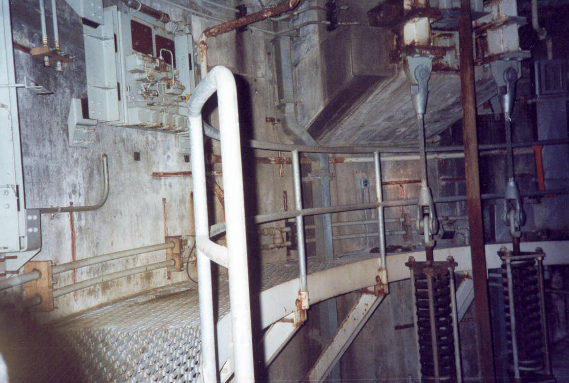
OSTF:
While there are many differences between the operational sites and the
OSTF, fundamentally, the two are constructed almost the same. Here
you can see one big difference where the access to the antenna silo was
actually at the catwalk level via a smaller tunnel. The
retractable gangway you see here covers the personnel tunnel when fully
retracted.
Image
courtesy of Fred Epler, photo by Lance Wright
|
|
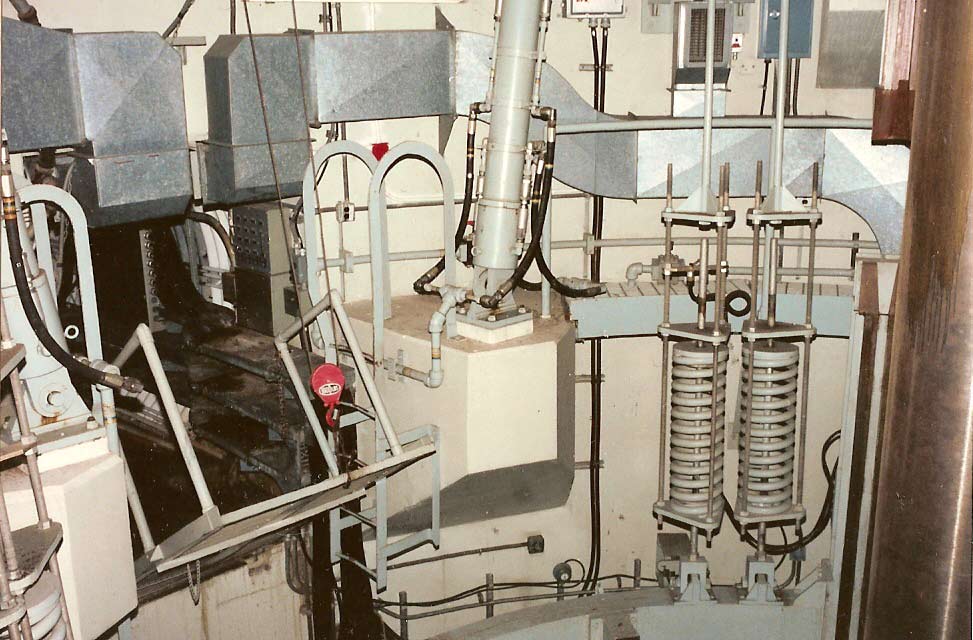
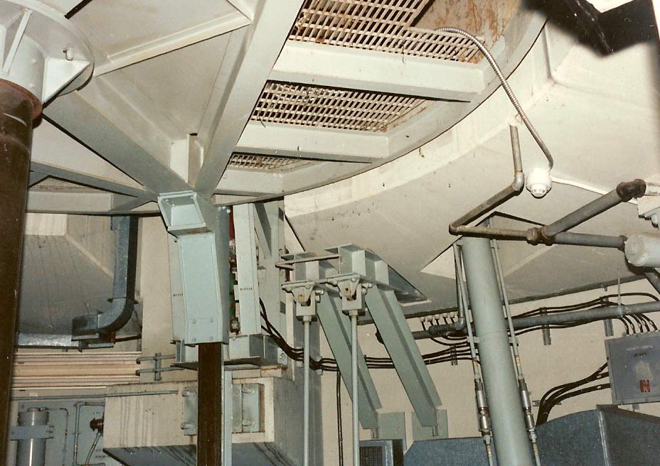
OSTF:
Door rams like these were rare as ball lightning in the salvaged
sites. I can recall seeing photos of them only once before on one
of the launchers out west. I am thrilled to see these pictures and
I have to marvel at how clean and new everything looks.
Image
courtesy of Fred Epler, photo by Lance Wright
|
|
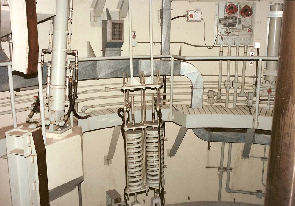
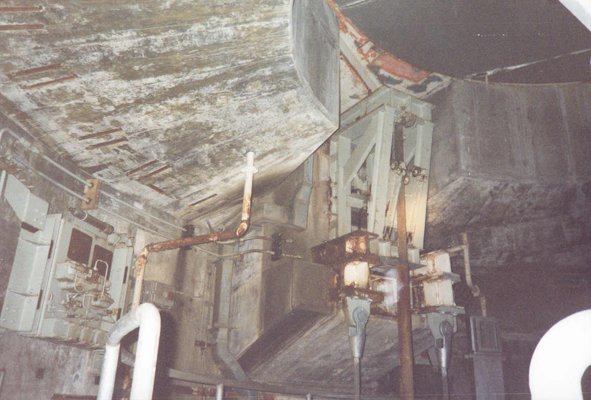
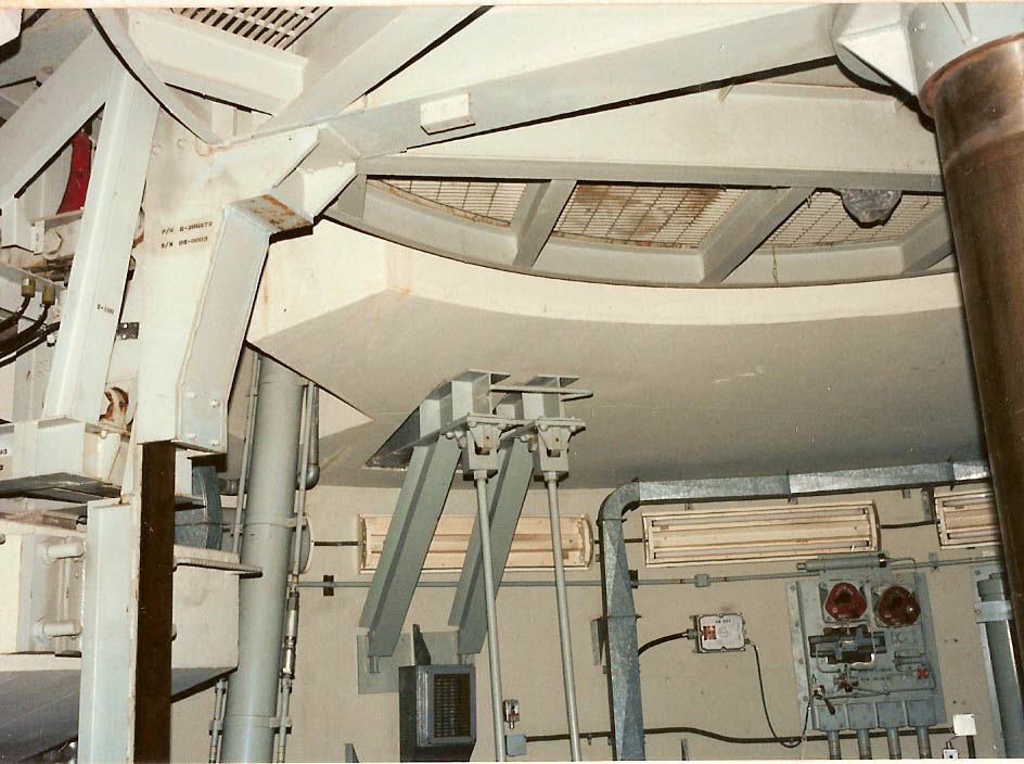
OSTF:
On inspection, you will notice that the shock assemblies in the OSTF
silos use solid steel rods for support and not the cables or wire ropes
you see at 724-C.
Image
courtesy of Fred Epler, photo by Lance Wright
|
|
1999,
Lowry 724-C: Catwalk level
|
A
Discovery on the Catwalk
My
first visit to the catwalk level of an antenna silo was interesting
and befuddling. Like most of the details in the complex, these
new features were strange and mysterious to me. I had only a
rudimentary idea of what the objects about me were for and this
newly-discovered area was just one more set of riddles for me to
solve.
Over
time, most of these puzzles would be laid bare until nearly all of it
made sense. All of it* save for one thing. This thing:
*
Okay, that's a lie.
Not all of it, but most of it.
|
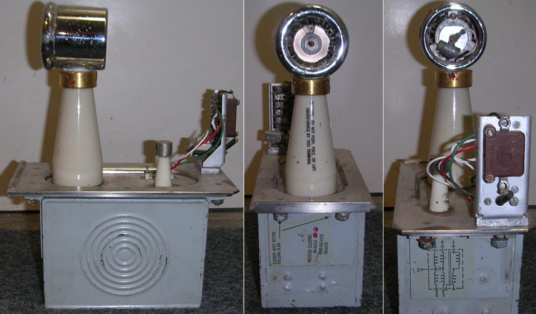
Side,
front and rear views. I tried to find someone who could tell me
what this is around 2002 when I posted some really lousy, blurry photos
of it that were so bad it's no wonder no one could help.
The
large terminal has a really strange-looking connector that looks like it
accepted some sort of plug or cable. You can see other details
better if
you enlarge the image by clicking on it.
|
This
mysterious object was discovered in 1999 on the catwalk level of
antenna silo B at Lowry 724-C. It is 12 inches tall, just over 4
inches wide and has 2 large terminals on the top with ceramic
isolators. It weighs about 12-15 pounds and when shaken makes a
sound as though it is filled with oil and ball bearings. It is
made by Western Electric which makes me think it is associated with
the antenna test equipment somehow but I cannot be certain if it is
original Titan I equipment.
I
absconded with the mysterious object but have been unable to divine
its purpose all these years. I simply have no idea what the hell
it is. What to do?
I'll
put out a world-wide call for help, that's what I'll do!
|
Side,
front and rear views. I tried to find someone who could tell me
what this is around 2002 when I posted some really lousy, blurry photos
of it that were so bad it's no wonder no one could help.
|
Take
the "What the Hell is That?"
challenge!
***
(UPDATE - Challenge has ended) Thanks to those who participated! ***
Be the
first to identify this strange object and its purpose and provide
concrete evidence (e.g.: a document, link or some source naming the
object and explaining its purpose and I will send you a small token of
my appreciation for your efforts: an actual piece of a Titan I missile
complex.
You heard right! I will send you this handsome
shock zone certification tag-- a real live Titan I artifact-- yours to admire and to pass on from
generation to generation as proof of your grand achievement.

Roughly
Actual Size!
Telling
me that it is a transformer will not suffice as it even says that it
is a transformer right on it, so you'll have to be more specific than
that. Good luck!!
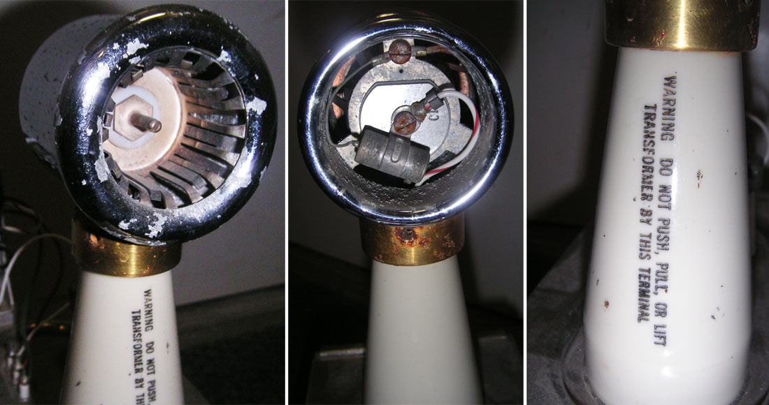
Here
are a few more photos to aid in its identification:
|
More
shots of the top, bottom, sides, etc. What the hell is that
thing?!
|
The
winner will have his or her prize shipped directly to them by mail
free of charge!
Yes,
all this can be yours! Do you have what it takes? Do you
have some useless knowledge of esoteric gadgetry? Can you answer
the question: "What the Hell is That?" Well can you?
If
you think you have the answer, contact
me with your astounding
evidence supporting your claim to be the first person to tell me
"What the Hell is That?"
and receive your awesome*
prize!
*
Awesomeness of
prize is subjective, no actual awesomeness guaranteed.
Individual perception of "awesome" may vary widely and
qualitative property of awesomeness may
in fact not be present at all either in or about the prize.
***
(UPDATE - Challenge has ended) ***
The
Results of the "What the Hell is That?"
Challenge:
For
those of you out there kept in suspense by the answer to this challenge,
I would be remiss if I allowed the mystery to torture you further, so
here is the winner of the What the Hell is That?
Challenge and the firstest and bestest answer to this oh-so-tantalizing
question.
The
Winner(s): Herein known only as
"Lefty" and "Smoke"--
yes, it was a collective effort-- they were the first to respond with
the correct answer and indisputable supporting evidence of that
answer.
Lefty's
hidden lair is rumored to be somewhere in the Tennessee hills, and Smoke's
underground fortress is said to be ensconced deep within the bedrock
beneath Michigan.
Congratulations
Lefty and Smoke!
I hope you can find an acceptable way to split the prize-- perhaps by
time-sharing or laser bisection.
Identity
and purpose of the Mystery Item:
A Pulse Transformer. Lefty's email described it thusly: a "transformer
to[sic] designed
to transfer pulses of non-sinusoidal wave forms between circuits without
basically changing the wave forms". Okay, I
thought. I am going to have to learn a bit more about radar and
the function of such a transformer before I can make sense of
that entirely..
Here's
what I came up with-- please folks, if I get something wrong here, don't
hesitate to correct me. Radar is not my forté so I implore
anyone who should see me engaging in misinformation here to let
me know
immediately!
Function
of the Pulse Transformer in the Titan I Guidance Antenna:
Hang
on, this can get a bit windy. Here goes:
The
Titan I missile uses a coded pulse to communicate with the missile to
both relay steering commands and to make corrections to the missile's
trajectory by timing the receipt of a beacon signal transmitted from the
missile-borne guidance package. The missile's beacon signal is
omni-directional and allows the guidance antenna to properly track the
missile and stay trained on its signal.
Transformers
typically perform two basic functions using the property of inductance
to "step up" or "step down" voltage using conductive
coils of wire with differing numbers of windings in the coils.
Inside
a transformer there are two coils-- a primary and secondary
coil in close proximity so that any current in the first coil will
create an electro-magnetic effect in the second coil; current on the
primary coil will induce a current in the secondary coil proportional to
the windings in the two coils.
A
primary coil will induce a greater output current in a secondary
coil with more windings and a lesser current in a
secondary coil with fewer windings than the primary. This
is precisely how residential power is "stepped down" from high
voltage mains at the power pole before it is routed to a home.
|
Dash-1
rudimentary diagram illustrating missile guidance. I added a few
labels as you can see. The pulse transformer was located inside
the antenna dome.
*
Regarding my little joke on the missile: I would like to point out that
I strongly regret the adversarial climate that emerged between Russia
and the US after WWII and which persists today. I truly hope that
any visitors to this site from the Russian Federation would not get the
impression that it celebrates nuclear weaponry or fosters any misgivings
between our nations. I sincerely continue to hope that peace and
diplomacy will one day make both countries wonder how such animosity
ever came about. I can dream can't I?
|
The
pulse transformer is so called because it produces very rapid, very
brief periods of high and low voltages-- pulses-- at precise power and
frequencies. These alternating high and low voltages produce the
rectangular "non-sinusoidal" wave form used by the guidance
system.
The
coded pulse used by the antenna is greatly amplified by the pulse
transformer for transmission with minimal distortion. The
"non-sinusoidal wave forms" described above refers to a
rectangular wave form (as opposed to a sine wave) which is well suited
to radar applications due to its distinctive nature.
Amplifying
the signal without changing the waveform (very much) is important
because a specific amplitude and frequency are required by the
missile-borne guidance package. If the wave form is too distorted,
the missile's guidance package will not recognize the signal and will
ignore it.
The
transformer was needed to increase the signal strength so it would be
capable of the range needed to communicate with a missile many miles
above the Earth as it raced toward apogee, at which time all guidance
ceased and the re-entry vehicle separated and continued to the target
using only gravity.
This
pulse transformer was apparently removed from the guidance antenna
before its removal from the antenna silo, perhaps with the intention of
being kept as a souvenir by someone on the salvage crew, but it looks as
though it was left behind.
Lefty
and Smoke sent me this
link, which provided the
objective evidence of their claim, which shows all three part numbers
(shown in the earlier photos above) positively identifying it and also
showing that one can apparently still purchase such a transformer!
A little follow-up reveals that you can buy your own GA-52814 Pulse
Transformer for around $3000-$4000 US dollars.
My
thanks to all those who responded!
***
(Challenge has ended) ***
|
1999,
Lowry 724-C: Catwalk level looking at one of the 3 guide rails and
up-lock assemblies.
|
In
the above photo, the light gray painted steel apparatus near the top
center is part of the up-lock mechanism. Arranged around the
perimeter of the silo mouth at 120-degree intervals are 3 locking
mechanisms that engage and lock the raised antenna platform in place
to maintain absolute stability during missile acquisition, guidance
and tracking.
For
accurate guidance it was imperative that the antenna, given ample
freedom of movement when the silo doors were closed, not be able to
move one iota while guidance operations were underway. The
up-lock mechanisms made certain that this stability was assured.
Once
up and locked in place, the antenna platform itself effectively acted
as a weather-proof and blast-resistant seal for the mouth of the silo
while the antenna was in use.
Of
course, I knew none of this in 1999 as I stood on the catwalk's steel
decking and concocted haphazard theories about the valves and
equipment surrounding me.
|
1999,
Lowry 724-C: This is a favorite of mine. Proof that surprises
await you at every turn in a disused missile complex. If
you look closely at this picture you will find a beer bottle setting on
a ledge near the lower left of the image.
Hmmm... This area is a good 30 feet above the floor with no stable
access anymore so I have a few ideas of how it came to be there:
-
Years
after the site was closed, some adventurous soul climbed up that
rickety ladder carrying one or more bottles of beer along and
pondered the function of what he saw in the dim beam of a flashlight
while enjoying a lukewarm
libation.
-
This
bottle was left by one of the salvage workers, probably after the
antenna was removed and while the doors were still open.
-
Working
in the operational Titan I sites was way more relaxed than I have been led to
believe.
I
think option #3 is the least likely. What
you really see pictured here is part of the heated glycol snow
melt/defroster system for the silo doors. This take-up reel kept
the glycol hose properly stowed, letting out line and moving as the
doors opened and then reeling the hose back up when they were closed
closed again. This same system was also installed at the entry
portal's heavy doors. The
missile silo doors actually used a different system of
"break-away" hydraulic rams to "nudge" the doors
slightly to break the grip of any accumulated frost, ice or any sticking
between the door surfaces so the main rams wouldn't be overloaded when
opening the doors.
|
|
OSTF:
A very clean and well-maintained look and fresh-looking paint for a
place built 5 decades ago. The OSTF had the luxury of a powered
winch for the gangway platform seen here. The Lowry sites had a
hand operated winch instead. You can see the door ram at center
and the large elevator platform ram on the right.
Image
courtesy of Fred Epler, photo by Lance Wright
|
|
OSTF:
Catwalk level showing the bottom of the antenna platform. The
antenna has been removed here allowing the platform to be in the up and
locked position even though the doors are closed.
Image
courtesy of Fred Epler, photo by Lance Wright
|
|
OSTF:
Platform again with one of the door rams and guide rails.
Image
courtesy of Fred Epler, photo by Lance Wright
|
|
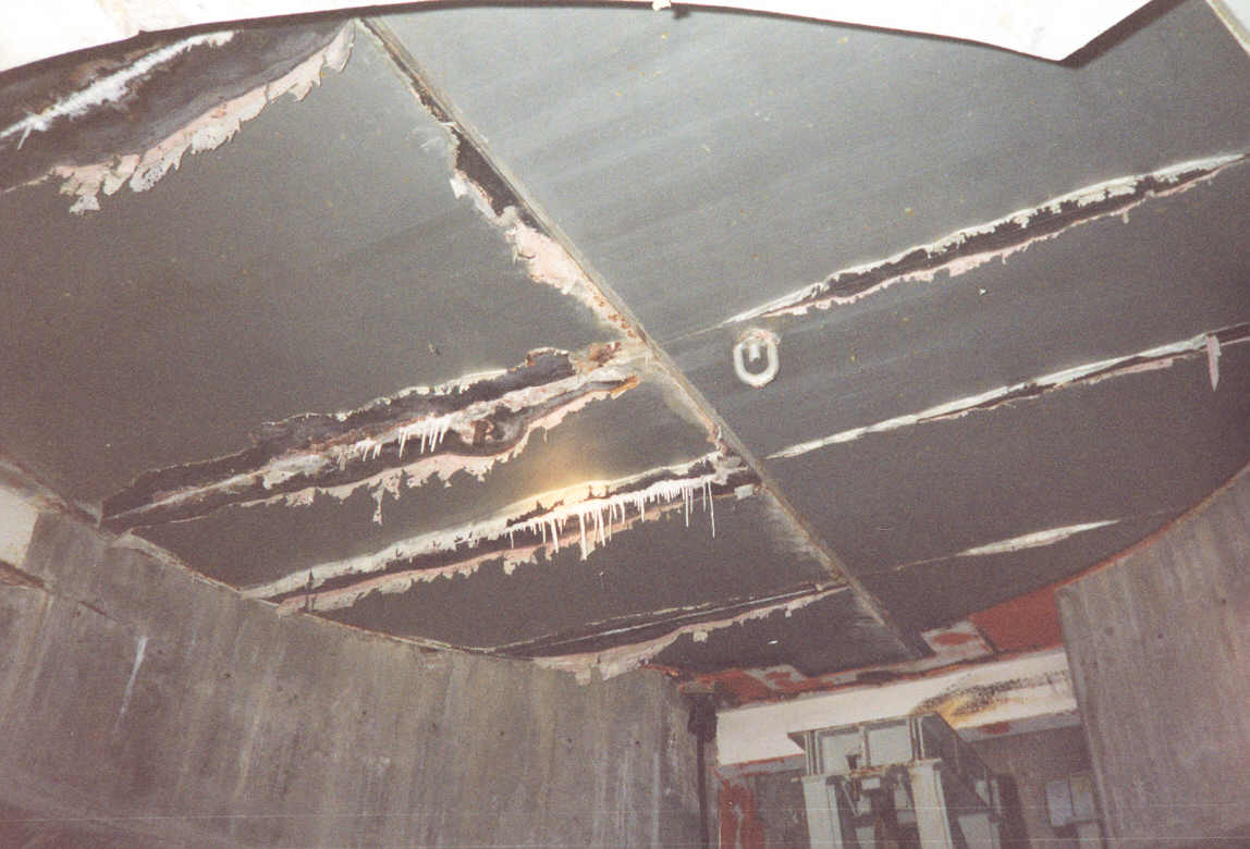
1999,
Lowry 724-C: Looking at the inside of the silo doors. Water has
been leaking in for so long there are soda straw stalactites forming on
the doors. Part of the up-lock mechanism can be seen in the
background.
|
All
things considered, the doors look pretty good after decades of
neglect, a bit of sanding and a new coat of paint and I think they
would look new from the inside. The outside is another matter as
the concrete has cracked and spalled and may have been damaged during
salvage operations if they were allowed to slam shut as in the case of
the missile silo doors.
The
rest of the interior, though dirty and cluttered with junk would clean
up quite nicely. Oddly enough, there was a mummified rabbit carcass
on the antenna crib platform in one of the silos. I really can't
figure out how it got in there as there are no visible openings to the
surface.
|
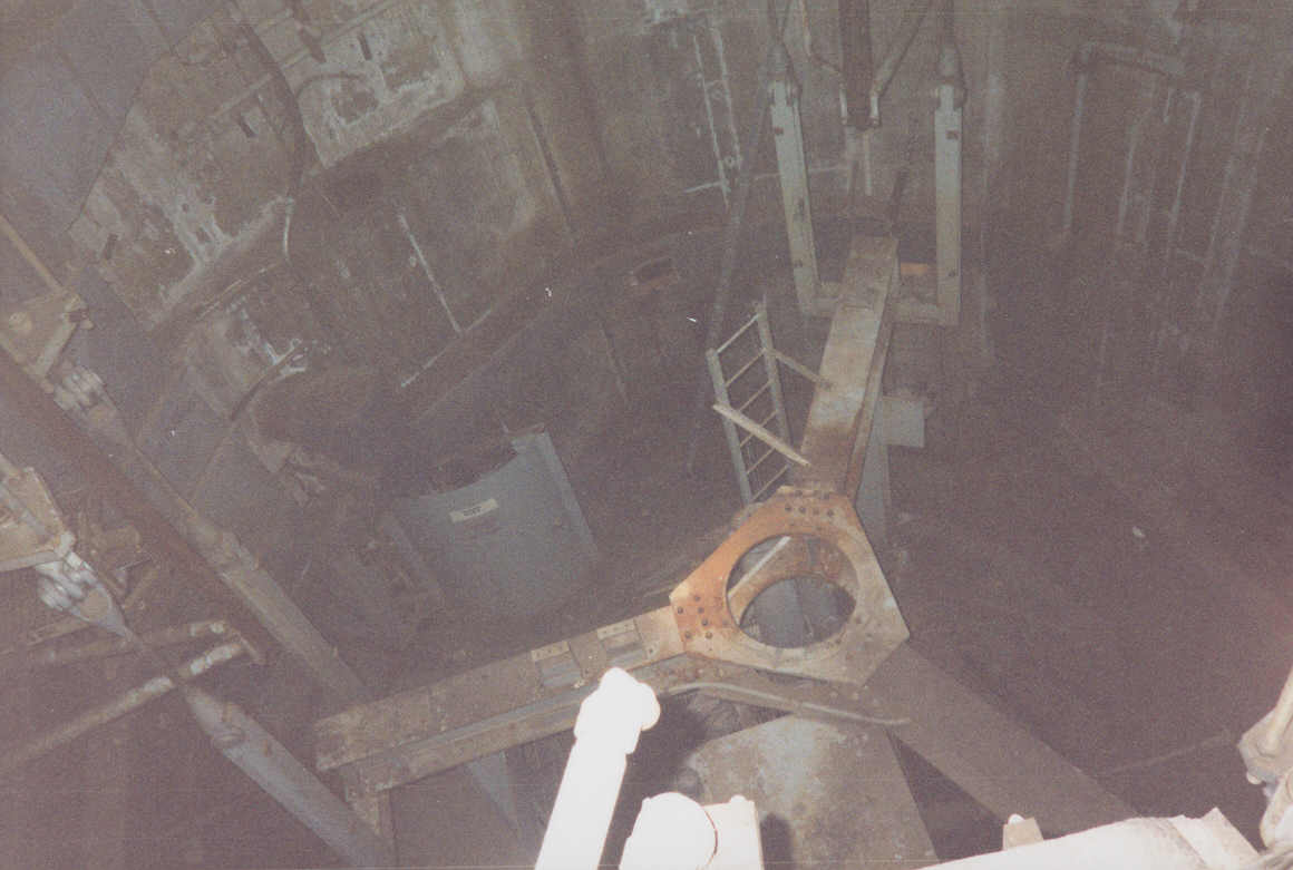
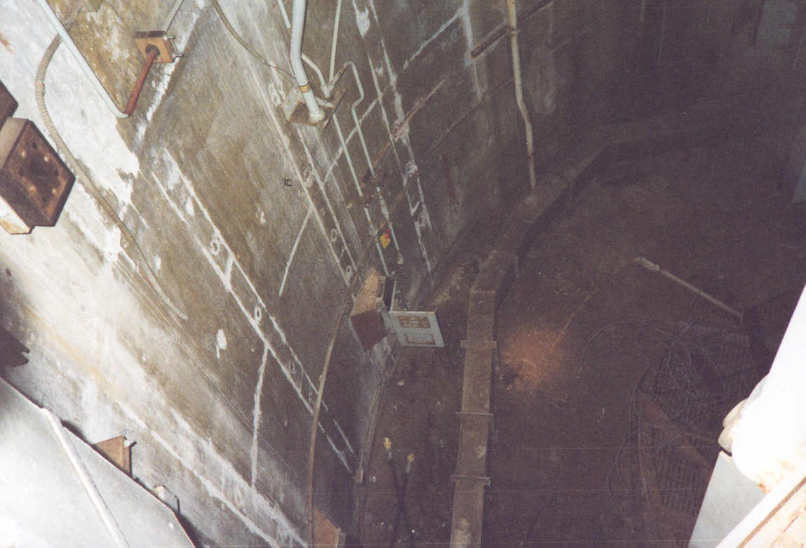
1999,
Lowry 724-C: Looking down into the silo from the catwalk level at the
the cribwork
|
|
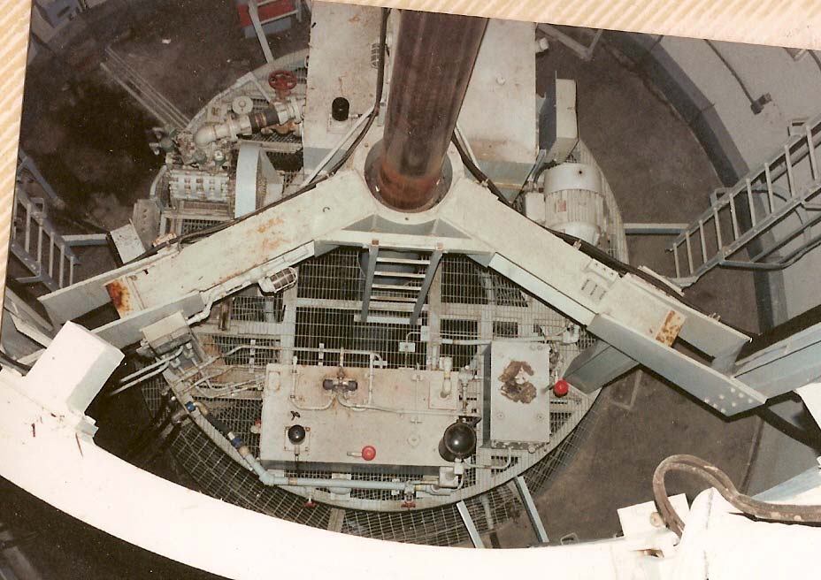
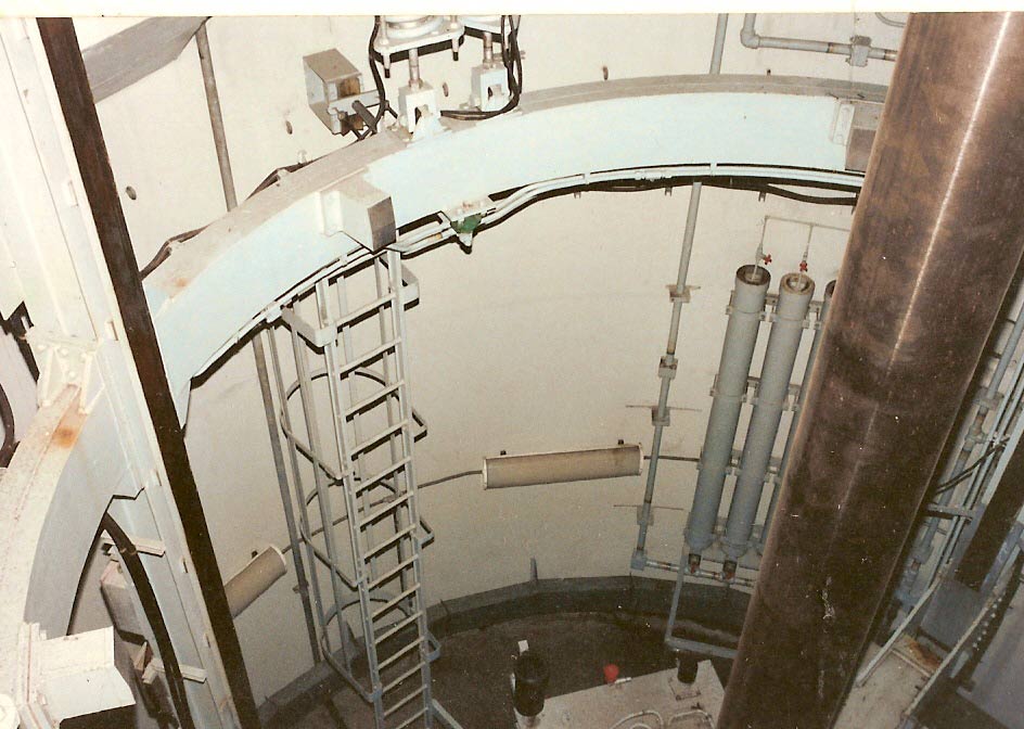
OSTF:
Looking down into the silo from the catwalk level. This gives a
good picture of just how much is missing from the Lowry picture above as
well as the often subtle differences in construction and placement of
equipment.
It
also underscores how lousy my camera flash was in my dark, underexposed
photos.
Image
courtesy of Fred Epler, photo by Lance Wright
|
|
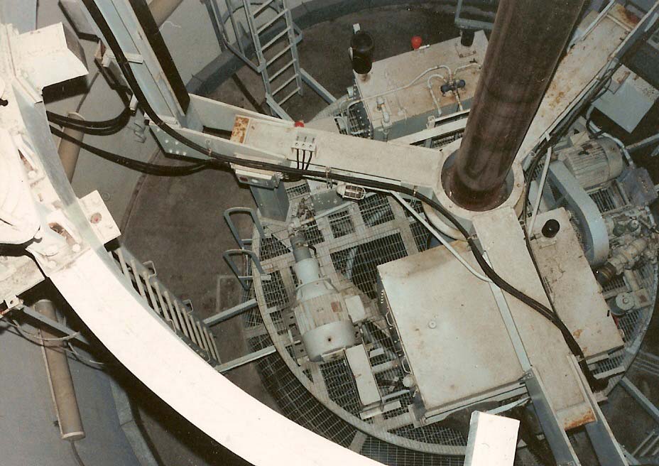
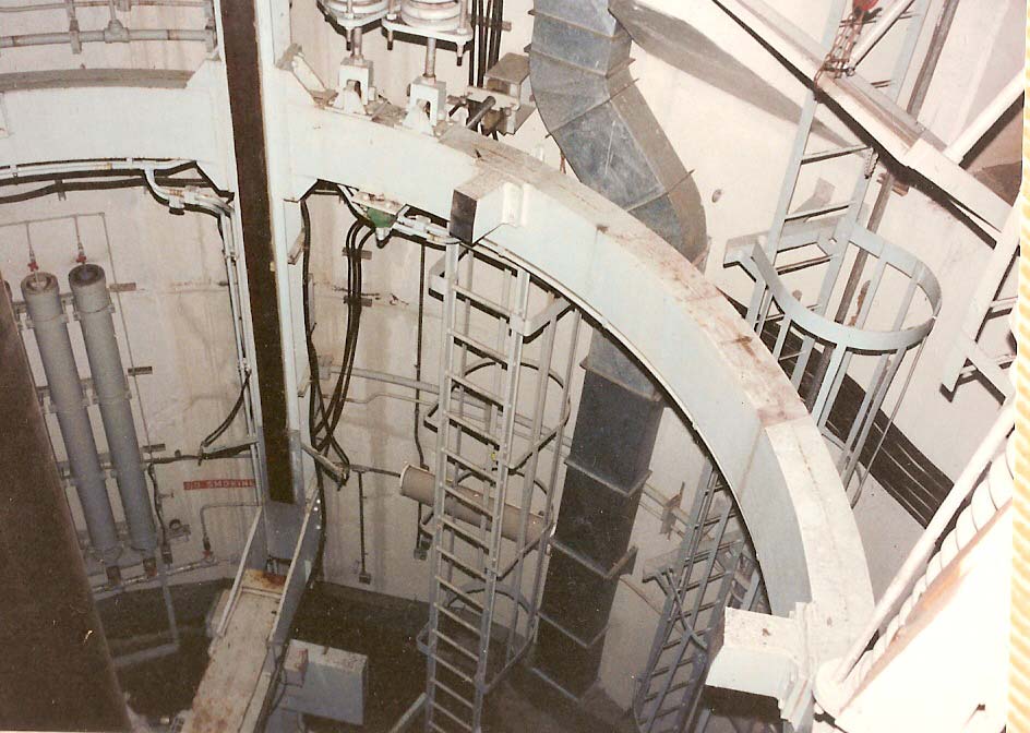
OSTF:
Another view of the silo from the catwalk level. This shot better
shows the ring structure used at the OSTF which can be seen arcing
through the photo.
Image
courtesy of Fred Epler, photo by Lance Wright
|
|
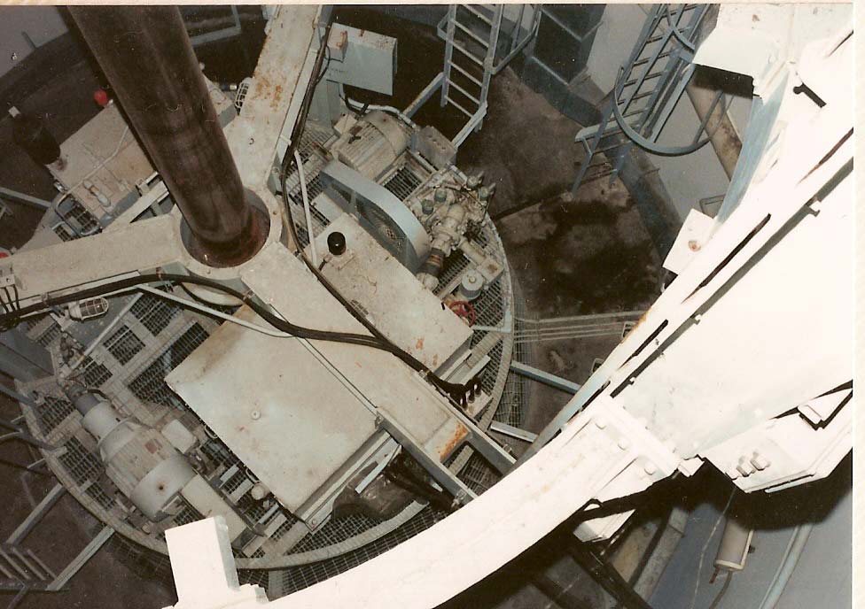
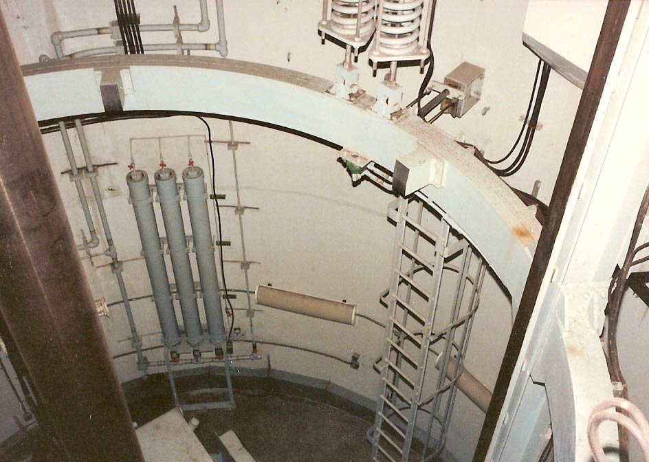
OSTF:
View from the catwalk
Image
courtesy of Fred Epler, photo by Lance Wright
|
|
1999,
Lowery 724-C: Another contrasting shot showing just how stripped out the
silos are
|
|
OSTF:
View from the catwalk
Image
courtesy of Fred Epler, photo by Lance Wright
|
|
OSTF:
View from the catwalk
Image
courtesy of Fred Epler, photo by Lance Wright
|
|
OSTF:
View from the catwalk
Image
courtesy of Fred Epler, photo by Lance Wright
|
|
OSTF:
View from the catwalk
Image
courtesy of Fred Epler, photo by Lance Wright
|
For
all the talk of uncertainty concerning a given piece of equipment's
function, the item in this next photo seemed to generate the most
speculation. It is a rather sinister-looking bit of apparatus,
like a cross between a fiendish death ray device and an air raid
klaxon.
|
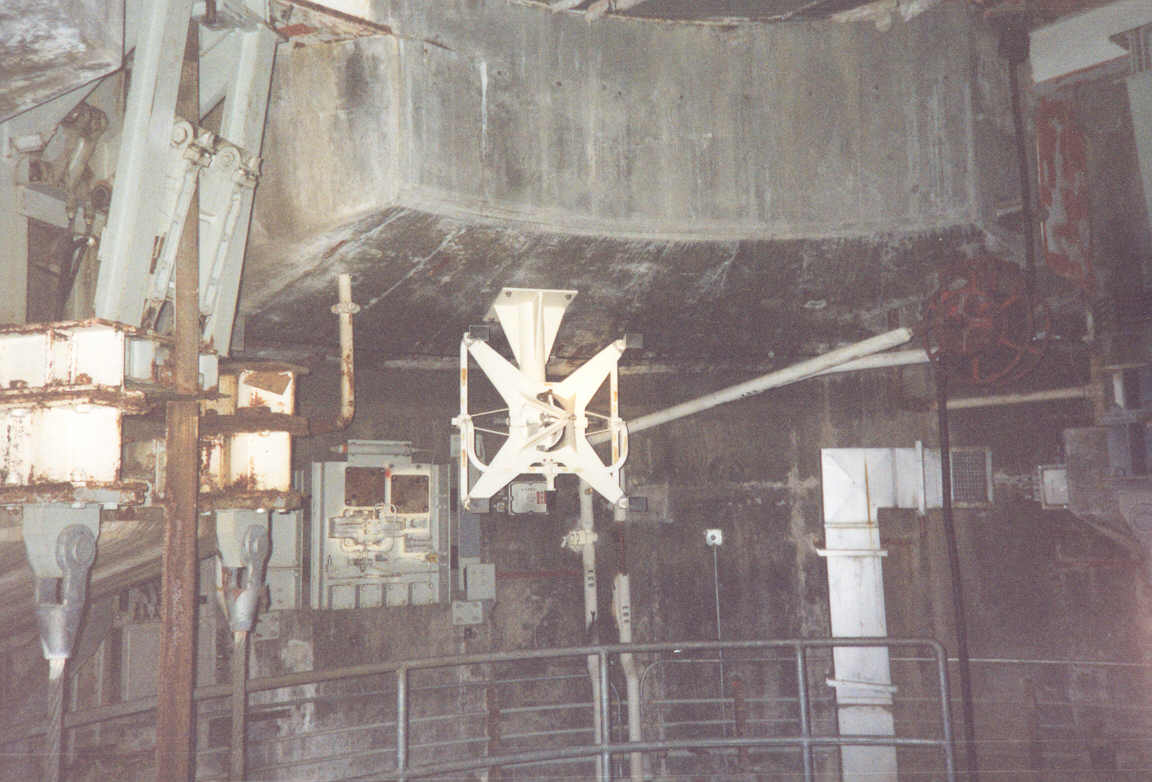
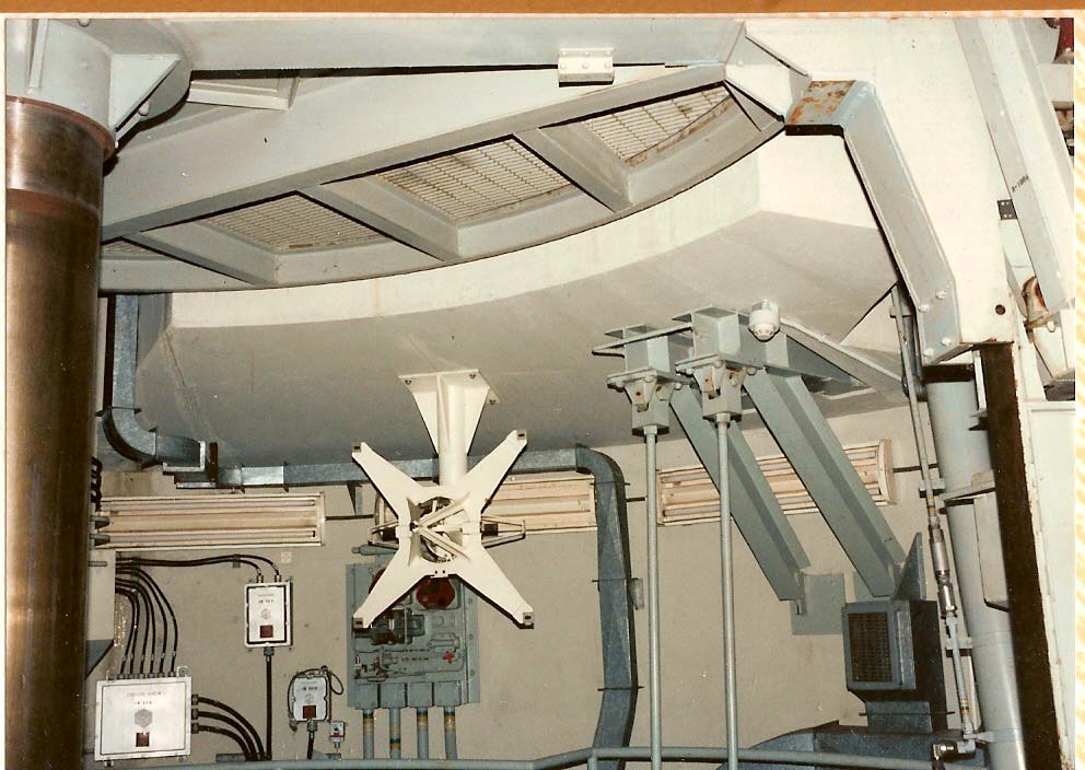
1999,
Lowry 724-C: The often misunderstood Feedhorn Assembly. What is
that thing?
|
Indeed,
we truly thought it was an alarm annunciator at first, but on closer
inspection discovered that it was supplied some kind of radio signal
via wave guide channels. Still, it seemed an odd appliance to
have down in the silo, but it was clearly a precision instrument as it
had finely calibrated scales for precise positioning in 3 axes.
There
are one of these assemblies in each of the antenna silos mounted
overhead at the catwalk level and directed toward the center of the
silo.
|
1999,
Lowry 724-C: A closer look at the enigmatic feedhorn assembly.
Here you can see some of the waveguide channels that split and route
microwave signals to a horn at each of the corners of the assembly.
|
So
what is this feedhorn assembly for you may well ask?
Well, I had my suspicions years back, but no way to confirm them until
years later. I will go into greater detail on this in a section
on the Titan I guidance system where I will cover its components and
workings.
For
now I will say that this instrument was part of the guidance system's
exercise and test set which allowed the guidance system to be tested
while the antenna silos were in the hard condition. The antenna
itself would interface directly with the feedhorn to run testing and
diagnostics by sending guidance signals back and forth.
|
OSTF:
The feedhorn assembly here has obviously been scavenged-- possibly for
replacement parts, but more likely for souvenirs. The 4
transmission horns at each corner are missing along with the waveguides
that carried signals to and from them.
Image
courtesy of Fred Epler, photo by Lance Wright
|
|
OSTF:
Another view of the feedhorn. Also visible here are the platform
hangers, made of solid steel instead of cables as they were at the Lowry
sites. Behind the feedhorn is the Lid Drive Panel (lid refers to
the silos doors in this case), which is a hydraulic transfer panel that
supplies one leaf of the silo's doors. There is an identical panel
on the other side of the silo to operate the 2nd leaf.
Image
courtesy of Fred Epler, photo by Lance Wright
|
|
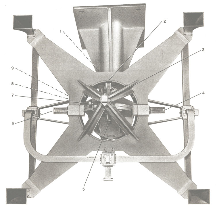
Feedhorn
Assembly G-332541
|
To
wrap up this section, just a couple more photos at the entrance to
antenna silo A.
|
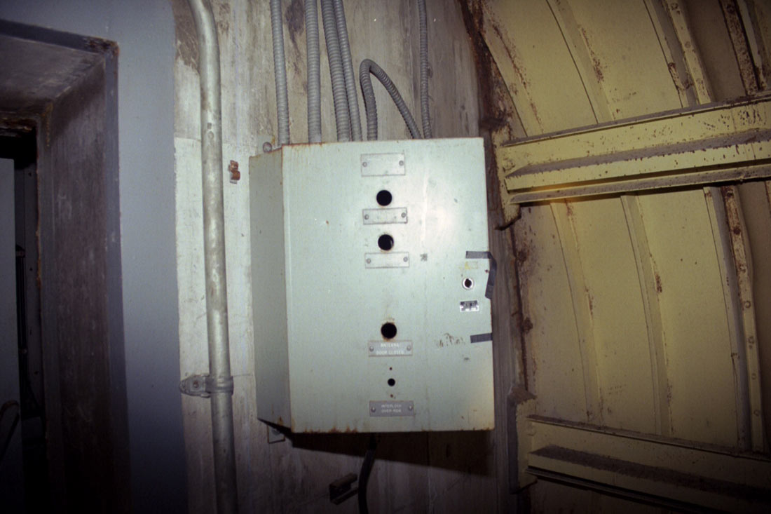
2005,
Lowry 724-C: The indicator panel for antenna silo A
|
|
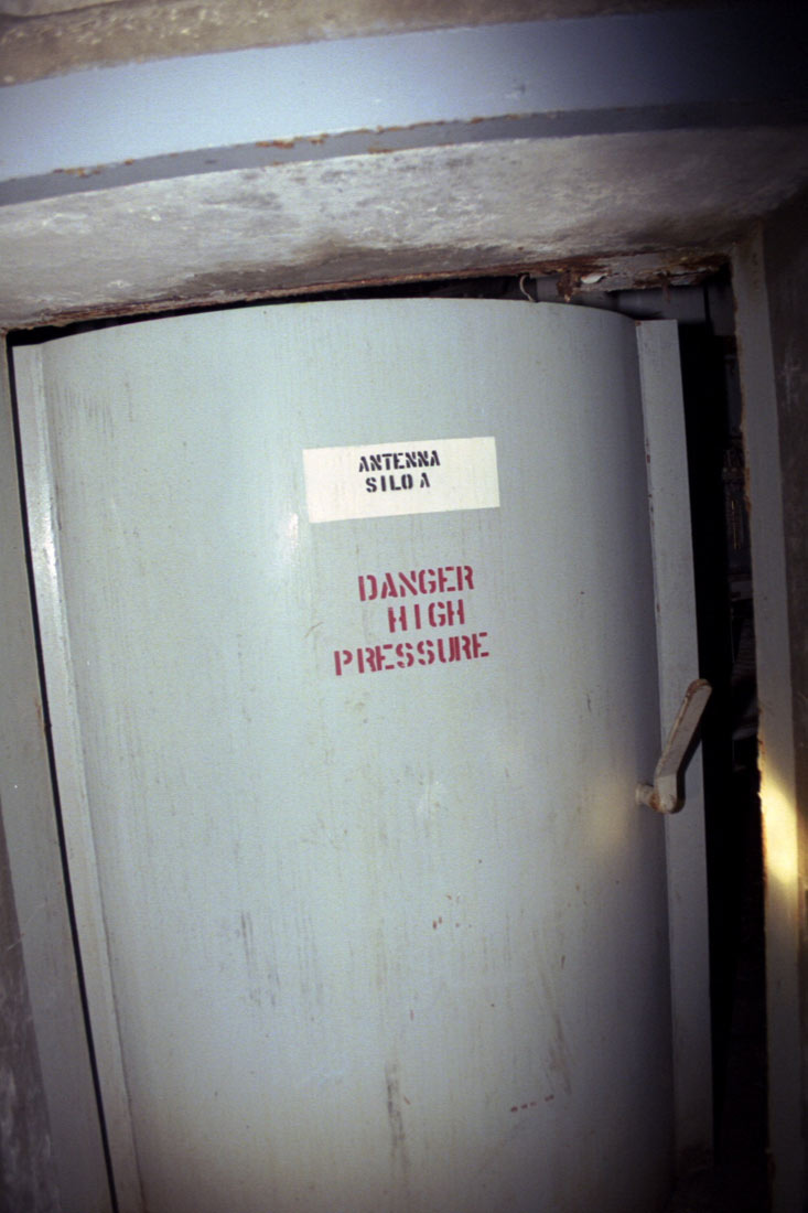
1999,
Lowry 724-C: Blast door for silo A. Looking at this vestibule
gives you a good look at the reinforcement around the doors where the
concrete was in excess of 2 feet thick to protect against blast
transmission into the tunnels.
|
The
antenna terminals were a dark and mysterious place when I first
trundled up the long personnel tunnel and lacerated my head on a
jagged pipe as I leaned in for a closer look at something. I
hope these sections have shed some light on the subject for the casual
visitor and the history enthusiast alike-- without the head wounds!
In
the next section there will be a pictorial explanation of the Titan I
guidance system, greatly (I hope) demystifying its components,
function and operations.
Antenna
Terminal Cont. (forthcoming,
please be patient)
|
Contact
| Site Map | Links |
Hosted by
InfoBunker