For
all the cost of research and development, for all the defense dollars
and planning, for all the labor, ingenuity and commitment by thousands
of men and women working together toward a common goal of security,
defense and deterrence, the focus of all this "energy" falls
directly on the missile silo and the weapon within.
|
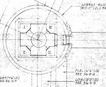
Another
lousy-quality blueprint showing the launcher silo and its quadrants.
When referring to a piece of equipment in the silo, its location was
generally specified by what quadrant (or Face: A, B, C or D) and service platform level it
resided on: e.g.: Face A, level #4.
|
All
the massive resources and an absolutely mind-boggling quantity of
man-hours spent realizing and creating this weapon, from the facility
that houses and protects it, to the factories that built the airframe
and the systems that make it work, to the crews and command centers
and myriad other supporting infrastructures to make it possible,
all exist around one comparatively small device: the warhead.
|
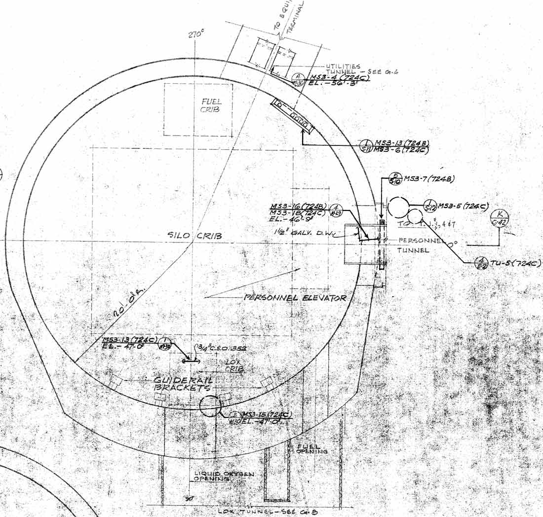
A
Slightly more detailed view of the launcher silo showing tunnel
entrances and locations of some main structures
|
It
is important after seeing all this technology, time, money and effort
expended, not to lose sight of the fact that it all exists, solely for
the purpose of transporting accurately, a piece of machinery about the
size of an automobile to a point on the Earth several thousand
nautical miles distant, as quickly as possible. It must do so
given only minutes to determine its destination and it must do so with
a high degree of success, landing within a fraction of a mile of the
coordinates provided to it.
|
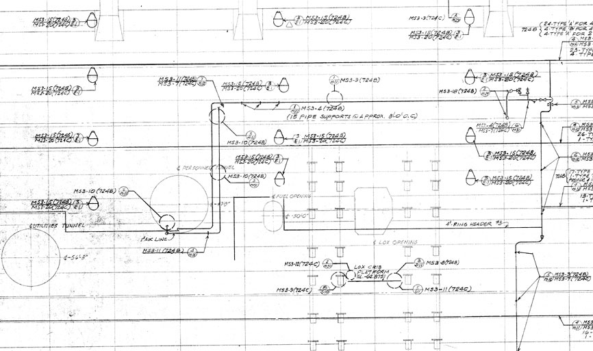
A
"roll out" view of the upper portion of the launcher silo
showing the many tunnels entering the silo in the upper 60 feet of the
structure.
|
Without
this small bit of machinery, all of this, the Titan Complex, its crew,
support equipment, command structure and the massive support base
built to make it possible would be completely useless.
Wasted. Ineffectual.
It
is for this reason that the silos, for most people, harbor the most
mystery and fascination over all other aspects of the Titan I weapon
system. Consequently, I felt justified in devoting the largest
amount of photos provided on any one section of the complex to the
silos.
|
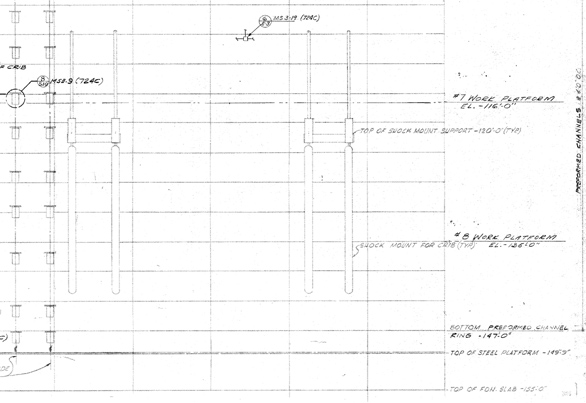
A
"roll out" view of the lower portion of the launcher silo
showing shock mounts, counterweight guide rails and locations of work
platforms 7-8.
|
Detailed
information on some parts of the silos is difficult to come by.
In particular, the cribwork as labeled in most blueprints is
represented by a box with NIC (Not In Contract) printed inside it as
the launcher elevator, cribwork and associated equipment were built
chiefly by AMF
(now QubicaAMF
as of 2005) and not The Martin Company.
The
bowlers out there will recognize AMF as the manufacturer of automatic
pin-setters at bowling alleys throughout the world. Desperate to
get more details on the cribwork, of which I had not seen so much as a
sketch back in 2001, I tried contacting AMF by phone to see if they
might have retained some information in a library or historical
archive. After all, AMF was a major defense contractor, a
manufacturer of very large, heavy equipment and as a result surely had
a lot of history behind it. AMF is in fact an abbreviation for
American Machine and Foundry.
When I contacted AMF, I got handed
off several times and finally to some bewildered rep who was neither
prepared nor inclined to assist me with my inquiry, which surprised me
very little but you have to try. He told me that AMF had nothing
related to missile silos, having devoted their efforts to peaceful
leisure activities such as bowling, golf and the like, as well as
competing with the Brunswick
company. He went on to tell me
that in place of "American Machine and Foundry" the company
had recently assigned to the abbreviated name the rather limp-wristed
slogan "Always Means Fun".
Looking
further I found that AMF's industrial divisions had been sold off so
clearly I was barking up the wrong tree. This was no longer the
same AMF that once manufactured nuclear power plants and military
hardware and it seemed they wanted to distance themselves from any
perception of ever having done so in the past. I did manage to
locate some product materials on the Launcher Elevator System and a
few other less interesting items, but never found actual plans for the
cribwork for the Titan I missile. If any readers out there have
had more luck finding such resources I would love to hear from them!
|
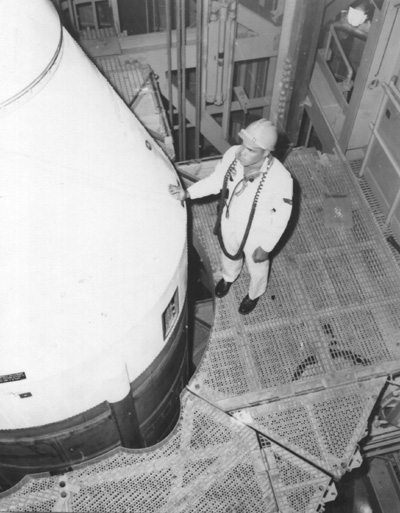
A1C
Brannon at silo level 1 inspecting the missile. Below him there
are 100 feet of missile, cribwork and a massive amount of conduit, wire,
piping, ductwork and heavily reinforced concrete.
|
The
WS-107A-2 launcher silo is an intensely hardened protective container,
40' in diameter and 155' deep, constructed from specially formulated concrete
and tons of reinforcing steel rods, some of which are well over an inch
thick.
|
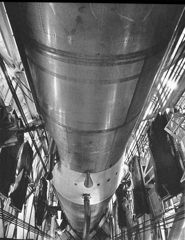
Looking
down the silo from the launcher elevator motor platform. An airman
is indicated by the arrow, standing at the base of the missile.
You can see the large, flexible LOX vent and relief line connecting to the 1st stage
near the center of the photo. This line allowed gaseous oxygen to
be vented as it boiled off during missile loading and standby.
|
The
missile is protected within the silo by 2 silo doors, each weighing
around 115 tons and opened and closed hydraulically by 2 pistons
that control movement in both directions. Within this steel and
concrete chrysalis, the missile rests atop its launcher platform,
ensconced within a massive steel cribwork comprising the launcher
system where it waits for the orders that will transform it from a
mass of inert metals and propellants into a weapon of terrible power.
|
Maintenance
at the base of the missile in another great shot of the cribwork. I
am sorry I don't know the names of the men shown in some of these
pictures performing missile inspection and/or maintenance. If
anyone can name these airmen, please contact me so I can give them due
credit.
|
The
missile platform is the actual elevator that raises the weapon to the
surface to launch and this platform is surrounded by a steel framework
over 12 stories tall and suspended on shock damping springs while in
the lowered position. This suspension protects the missile from
shocks (read: "nearby nuclear explosions from Russian
ICBMs") which might otherwise be transmitted to it through the silo
structure which is designed to carry shock loads down into the
surrounding earth without damaging the weapon.
Beneath
the missile platform there is a scoop-shaped structure called the
"flame deflector" or "flame bucket" constructed of
heavy steel and lined with a thick layer of heat resistant concrete
which would redirect the rocket exhaust out to the side of the
launcher and away from the silo. Special platforms would seal
the mouth of the silo to keep the heat and flame from damaging the
launcher and the whole platform was sprayed down with a deluge of
water to cool and protect it.
Voice
of Experience - A Titan I Engineer
Tells The Tale of the Flame Deflector
Recently
I was fortunate enough to be contacted by a man who worked on the
Titan I project--one of very few I have corresponded with. An
engineer for AMF, he worked on what may seem like a minor system of
the Titan launcher, but was actually a critical component and
engineering challenge upon which the final specifications and design
of the launcher silo itself were hinged. Here in his own words
are his account of the flame deflectors' operational development and
design:
A Memoir for An Epitaph
The Titan 1 Silo Lift Launcher Flame Deflector
Early in 1958 I transferred from the Nuclear Engineering Division of American Machine and Foundry for a special assignment in the then top secret Titan 1 Silo Lift Launcher
Project. Managers of that project were particularly concerned about the design of a so-called dry (uncooled) flame deflector which was to be part of the elevator structure.
It was clear that the size and configuration of the deflector would determine the size and configuration of the elevator and, indeed, the diameter and depth of the silo as well as design details of the
silo. Accordingly I was told to develop a design concept as rapidly as possible that had a high probability of success.
The task did seem formidable:
1. There was no design precedent. Ground based deflectors for Titan engines were massive concrete structures using massive water deluge during firing.
2. The forces and thermal impact were severe: 300,000 pounds of engine thrust to be turned 90 degrees with temperature exceeding 3000 degrees F and exhaust velocities probably above Mach 2.
3. Spray cooling of the deflector was required after either an abort or launch to enable lowering the structure into the silo.
4. A refurbishable structure was required but no fragmentation of the deflector was permitted which could damage the
missile, and, no flames were permitted to enter the silo during firing.
In about six weeks I had developed a design I was reasonably confident would work.
It consisted of a 90 degree rectangular cross section "elbow", 12 feet high x12 feet wide x12 feet deep.
It was to be constructed of steel plate approximately 3/4 inch thick, suitably reinforced with structural members, with the back plate (the impingement area) sloped at about 30 or 40 degrees to the vertical (I don't remember exactly).
The key question was what to use to protect the back plate from being destroyed by the impingement of engine exhaust.
I calculated that steel would start to melt in about 1 second at these conditions but copper (yes! copper!) would not melt for 5 or 6 seconds which was the time that the rising missile exhaust cone would be in contact with the deflector.
Copper acts as a heat sink to soak up and diffuse the heat of the blast.
Commercially available material approximately 1 inch thick was selected. I will leave the type and style to the imagination rather than reveal any "know how".
This design survived a detailed technical review by Ramo Wooldridge, technical advisors to the Air Force.
The concept also passed, quite successfully, scale model tests under Nike engines at Aerojet's test facilities in Azusa, California and a full scale test on a half width deflector (one engine) at Aerojet's test facility in Sacramento, California.
At that test, a technician asked me, probably not in jest, where did I want all the pieces sent after the test.
This was an understandable reaction since the deflector was slung up near the top of the 30 or 40 foot high concrete (w/deluge) deflector and appeared poised for obliteration under a 30 inch diameter engine.
I am pleased to say the deflector survived with only heat staining of the copper surface and no buckling or warpage with the water spray cooling after the 6 second firing.
Back in Greenwich, CT, the managers seemed to breath a bit easier.
At the full scale firing, I noticed that the concrete deflector used for hold down firings and concrete encased steel members in the vicinity had been hit by engine exhaust in the many test firings conducted.
While pock-marked,the concrete seemed to survive. Accordingly, I asked Aerojet to remove the copper and tack weld expanded metal to the back of the deflector and "gunite" a 3 to 4 inch layer of concrete.
When suitably cured, this was fired on and, while significant melting had occurred in the center of impingement, no penetration occurred and no cracking even with the water spray after firing.
I recommended that the concrete lined deflector could be used even if not quite as elegant as the copper faced unit.
No refurbishing was needed of the latter while the concrete would have to be refurbished between firings (that procedure was tested and worked ok
). Evidently the concrete lined deflector was used. I left AMF in October 1958, shortly after these tests (for a better career opportunity) and didn't find out how things turned out until I recently probed the Internet for information.
Details are abundant regarding the Titan 1 program and all indications are that these silo lift launchers were successfully made operational (see
http://www.designation-systems.net/dusrm/m-25.html).
Incidentally, many skilled engineers worked on this silo lift launcher under strong mandates from project managers regarding the urgency of the mission.
Cost was probably not optimized but evidently an important deterrent was operational in a timely way.
When it was proven that missiles could be launched from within a silo if the exhaust chutes were properly designed, the silo lift launchers and the Titan 1 became obsolete.
I am proud to have been a part of the team that developed the silo lift launcher.
PNR 10/1/08
My
thanks to the author for sharing his story and further enriching the
history of this site. He would later write another memoir
to supplement the first, providing further details about his work with AMF,
early US ICBM weapon systems development and the Silo-Lift
Launcher Flame Deflector engineering challenge. I am pleased to
present his memoir to you:
Memoir #2
The Silo-Lift Launcher Project at American Machine & Foundry
(ca 1958)
In 1957 I accepted an offer to work as a Senior Heat Transfer Engineer with the Nuclear Engineering Division of American Machine and Foundry in Greenwich, CT. Eisenhower had announced his
"Atoms for Peace" program and this offer from AMF seemed a perfect utilization of my background. I had about ten years of experience in heat transfer projects in Oil Refineries, Chemical Plants and Power Plants and at the time, I was an Assistant Professor in the N.Y. State University System teaching engineering and doing consulting work in Heat Transfer.
My assignment at AMF was to analyze the heat transfer aspects of a nuclear reactor core for a project to build a power reactor at Elk River, MN. The work was of great interest to me and quite challenging. The reactor was to be one of the earliest boiling water power reactors, generating enough power for a rural cooperative power association (22MW); small by today's measures but quite significant then.
When my analysis work was essentially complete (in conjunction with the physicists on the project), we were sent to present our designs to a Dr. Walter Zinn. He had been hired as a consultant to AMF and was one of the
"fathers" of Atomic Energy; a co-worker with Fermi at the first demonstrated chain reaction. He had also headed Argonne National Lab, spearheading atomic energy power applications.
At our meeting, I presented all the heat transfer and fluid flow analysis I had done on the reactor core. The work was received favorably by Zinn but he asked if we had taken into account a so-called
"water-metal" reaction that might occur in the event of a nuclear fuel melting. We had not-- our physicists considered it a highly unlikely event. However, we were asked to do so and to design a containment structure that could withstand such energy release. The result was a containment cost increase which resulted in a fall-out on price between the AEC and AMF. The project was canceled at AMF and I suddenly found myself with little or no work. It was at this point that I got a call from a manager in the General Engineering Division of AMF who headed up a part of the design of the Silo Lift Launcher. He needed someone to design a so-called dry (uncooled) flame deflector for a missile launcher project. Needless to say, I accepted the invitation. Next day I was escorted to a room apart from the area where the launcher project work was being done (actually I found out later it was in a proposal stage). I needed to get a secret clearance; my nuclear Q clearance was not enough. This was rushed through and in a bit over a week I was formally a part of the project team. In the interim I had been given unclassified missile launcher histories, none of which made much sense to me in my
"limbo" situation. When I was introduced to the manager of the Elevator Design Section, things began to clear up. I quickly grasped the nature of the task and set about developing a design. AMF had adopted a rather formal and well conceived procedure for the management of such complex projects. The project was subdivided into various systems, subsystems and components. Each responsible engineer was required to develop:
1. A DCL (Design Concept Layout)
2. A DDL (Design Detail Layout)
and work to coordinate these with any interfacing parts of the project. My
"Memoir" on the development of the Flame Deflector, covers the high points of the program although there are interesting
"side-bars" I can recount.
Our design group was almost entirely housed in a building on Steamboat Road in Greenwich, CT which was used in WW2 to build P.T. Boats. It had a
"tin" roof, was poorly air conditioned with some window units and was generally uncomfortable.
As noted in memoir #1, I had to review my design with Ramo Wooldridge Co, technical advisors to the Air Force. They were housed in splendid conditions in Los Angeles. The lobby alone was awesome: potted palms, leather couches and a receptionist who must have been a beauty queen. Quite a contrast to the Steamboat Rd facilities in Greenwich, CT.
My design review with Ramo Wooldridge was initially met with some unspoken skepticism. After reviewing my detailed transient heat transfer calculations showing the high likelihood that a copper faced deflector would survive a launch, the RW engineer and I became drinking buddies that evening.
When I got back to Greenwich, I was told to make a visit to AVCO in Massachusetts. This particular division of AVCO was working on the design of the nose cone for atmospheric re-entry with the war-head. Evidently they had established a copper nose cone as
their reference design. That was news to me. Evidently I had unknowingly pursued the same technical path as AVCO; the conditions (thermal & velocity) of re-entry are very similar to the thermal conditions of missile exhausts. I established a 'need to
know" and went to AVCO in Massachusetts. I found they had spent over $10 million in experimental work to determine the efficacy of a beryllium-copper nose cone. I was now even more confident my copper faced design would work.
In memoir #1, I left "to the imagination" what I used to line the back plate (impingement area) of the deflector. I used commercially available copper electrical bus bars 5
7/8" wide, 1" or 1.5" thick (I don't remember which; I analyzed both) by about 20 feet long; 24 of them across the back of the deflectors. These were mounted on steel channel irons with studs through slotted holes; the channels were in turn secured to the deflector's back. It was this design that was tested at Aerojet in Sacramento in a full-scale test under one engine (½ a deflector). When I arrived at Aerojet's office in Sacramento to witness the test, an engineer came up to me and, with German accent, said
"Ah you are the designer of the copper deflectors? At Peenemuende* we used green
logs!!" I thought about that and wondered how often they might have to be changed in a silo stand-by situation.
* Germany's rocket development facility under Von Braun during
WW2.
You will note that the AMF document "Titan WS107A-2 Launcher System" dated July 1958 shows a copper colored deflector. You should include this document up front in your web site even though it is in your document library. It formed the basis of AMF getting the go-ahead on this project. The rest of the story is partly in memoir #1. Now for some of the people and organization highlights at AMF.
George G. was manager of the Elevator Platform Group. He was a seasoned mechanical engineer, kept us focused and on-schedule. He respected the abilities of the individuals in his group and by occasional questions satisfied himself as to the progress and competence of his people. I'm sure this was the case in other groups.
One engineer in particular stands out in my memory. He was responsible for the design of the locks needed to secure the elevator to the crib. In turn the crib was locked to the silo wall. This rigidization was critical for a successful launch. The locks had to withstand the forces imparted to the deflector by the engines at launch
(300,000 lbs horizontal & vertical due to turning 90 deg.) and other weight effects plus wind effects. A tough design job! The engineer involved seemed deep in thought for many days until finally, activity developed in earnest. I'm sure he came up with a great solution. Web site information clearly indicates the efficacy of the designs.
I had a Japanese draftsman working for me in laying out my DCL and DDL. I believe he thought I was a bit crazy at first but
"came around" as tests proved my approach.
One day in mid 1958, a member of our group came into the office and said
"Secret project? -- What secret; Aviation Week has a story about it." I didn't see the article (have contacted Aviation Week to se if their archives have it) but the Internet commentaries on the Titan 1 mention that we (the U.S.) made the Soviet Union aware that we had deployed a large number of missiles in hardened underground silos. This was evidently done about 1961-62; about the time of the Cuban Missile Crisis. In fact, at that time we apparently had both the Titan 1 and the Atlas in Silo-Lift operational sites: approximately 126!! It is commented that the Soviet Union backed-down in Cuba when this information reached them (or they understood the full import of it). In short, the massive efforts in building the Silo-Lift launchers paid off as a true deterrent.
Those of us who lived through the Cold War years of the early 60's remember well debating if we should build bomb shelters in our basements. In the end, only our strength made peace possible.
Many of the people in AMF's Nuclear and General Engineering Divisions drifted away as projects dwindled and AMF lost commitment in these areas. My supervisor in the nuclear work, a brilliant engineer, went into the printing business and became a leading authority on lithographic printing, published a book and many technical papers on the subject. Others went with companies such as Perkin-Elmer on the Hubble Telescope project, Combustion Engineering in Nuclear etc. I eventually joined Rockwell International in a senior technical position with their industrial group and interfaced with the Aerospace Group on occasion thus able to see the advances in that technology again.
In summary, I am pleased that some of my work was helpful in the defense of our country.
PNR 5/29/09
Pete
followed with a third memoir detailing the ongoing evolution of the
unassuming flame deflector following the design of the Titan I
launcher system and its influence on later launcher design. It
may not seem like it, but as he illustrates, the deflector's design
had far-reaching cost implications on other major parts of the
launcher system:
Memoir #3:
The Titan I Flame Deflector
"The
rest of the story"
Since writing Memoir #2 (see
above) I have investigated the history of the Titan I flame deflector
in regard to actual performance in Silo-Lift installations to see if
the performance was as good as predicted in scale model and full-scale
tests during the design phase.
The first Titan I launch was on
an OSTF (Operational Silo Test Facility) at Vandenberg AFB on
September 22, 1961. It was vividly described by Bob Considine a
well-known news reporter of the time. A brief quote:
"The white Titan rose from
its 165 foot deep silo... engines started... a blinding rush
of flame... it sat there two maybe three seconds... and lifted itself
with regal leisure."
Other successful test firings
were implemented. The flame deflector performed successfully, as
predicted. This, it should be emphasized, was an important milestone
in "dry" (uncooled) flame deflector design. Prior flame
deflectors used for hold down tests used massive water deluge on the
deflector surface; an impractical design for the Silo-Lift launchers.
In 1960, the Army Ballistic
Missile Team, under Von Braun, was designing a launcher system for the
first of the Saturn rockets. At first the deflector design used a 10°
impingement angle (this is also the slope angle to the vertical).
However, this results in a very high deflector; as much as 40 or 50
feet. That height makes for a very expensive launcher platform height
to say nothing about the expense of the deflector itself. The Saturn
ground support system design was delayed for 6 months when the
designers probably came upon information regarding the successful
design of the Titan I deflector with a 35° impingement angle.
The design of the launcher for
the Saturn was revised to a 30° impingement!
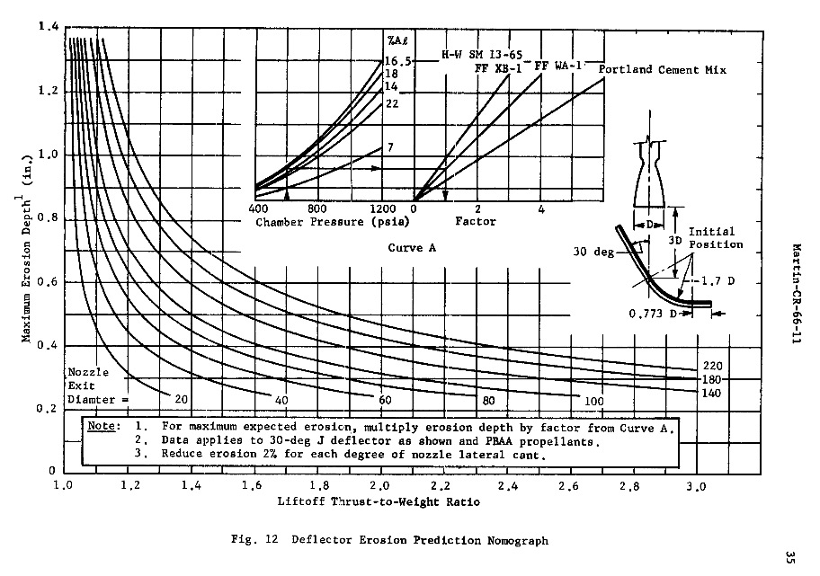
While I was investigating these
developments, I came upon a publication by Martin Marietta, dated
March 1968, entitled "Design
Handbook for Protection of Launch Complexes from Solid Propellant
Exhaust."* That publication essentially confirmed my
Titan I design. In Figure
12, they show a 30° angle deflector with one of the design
lines for Portland cement. When this chart is used for low or zero
alumina (alumina is found in solid propellant engine exhausts), it
essentially confirms the erosion experienced by the Titan I Portland
cement lined deflector for liquid fuels.
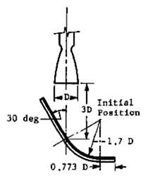
fig.
12 (detail)
While making these
investigations, I contacted the Association of Air Force Missileers.
They were helpful in providing much background. The Director of that
organization, Charlie Simpson, Colonel U.S. Air Force retired, put me
and a young ground support engineer at the Kennedy Space Center, into
contact. The latter was seeking information on the Titan I launcher
design. He and I have corresponded and had telephone conversations
regarding my deflector design. He is to be commended for tracing back
to the Titan I design since he recognized it played an important role
in almost all subsequent launcher deflector designs.
With the operational readiness
of 126 Silo Lift Launchers (54 Titan I and 72 Atlas F) during the
Cuban missile crisis, perhaps nuclear war was averted.
P. N. R. September 2012
1
AA FM, Vol 3, No 4, October 1995
2
Moonport: A History of Apollo Launch Facilities and Operations, Ch.
2-7.
P.S. My design used a 35°
impingement and all pre-construction tests were satisfactory.
Aerojet, in report No. 1457, indicted some (minor) improvement might
be possible using a 30° impingement. AMF decided to retain the 35°
but subsequent investigators chose the 30°.
Note that the Atlas F
Silo-Lift deflectors were patterned after the Titan I although they
had to be somewhat wider to accommodate a three-engine
configuration. AAFM, Vol. 3, No 4, October 1995.
* I
have linked the cited document from NASA's web site but noticed that
it can have problems loading fully.
In January 2015, I heard from Pete once again; Pete had been giving serious thought about the current Space Program, in particular the Space Launch System or SLS, with its mission to replace the discontinued Space Shuttle program to take payloads and astronauts into orbit. As an engineer tasked with developing the flame deflector for the Titan I, and resultantly, a design that has been established as the standard configuration employed over the ensuing decades, Pete felt this latest iteration of space launch system with its flame deflector configuration could benefit from additional consideration and talks about the evolution of flame deflector technology and expands on his experience working in the Titan I program.
Memoir #4 - Epilog
"From Titan I to the SLS (Space Launch System)"
This epilog is written to review the advances in Flame Deflector Technology since the development of the Titan I Flame Deflector as described in the three memoirs above, to amend or correct those memoirs as required retrospectively and to acknowledge the importance of this website, Titan I Epitaph, as a valuable focal point for information collection on this historic program.
The Titan I website has been instrumental in connecting people involved with the design, operation and technical history of the Silo-Lift launcher. It's collection of photos, documents and commentary will preserve the valuable information on this first operational missile deterrent of the Cold War.
When I joined the Titan I Silo-Lift Launcher group at AMF, with the assignment to develop a dry (uncooled) flame deflector, I arranged to visit Reaction Motors' Test Facility in Denville, N.J. to get some idea of Flame Deflector Technology. I was escorted to the test site, and observed a rather massive deflector (from a distance), blackened by test firings that looked like a concrete emplacement in the hillside and with ports for water deluge. I was probably mistaken; the deflector was more likely of steel construction. Probably others of that era, such as Aerojet in California were also steel with water deluige. So much for corrections.
The evolution of flame deflector technology from Titan I to the requierements of the SLS (Space Launch System) is outlined in this epilog.
The Titan I Silo-Lift Launcher required a compact, uncooled (no water deluge) deflector. The profile developed for that project, a so-called "J" deflector, has been adopted by all major launch facilities for subsequent rockets. Even today, the profile for the SLS which is noted to be very similar to that for Apollo is virtually identical to the Titan I Silo-Lift deflector, albeit much larger.
The deflector for the Titan I Silo-Lift used a gunited protective refactory-like surface on the steel backing. My instructions to Aerojet was simply to call in a contractor to gunite a 3 or 4 inch layer on expanded metal tack-welded to the back of the deflector. The gunite, to expand on what is described in the memoirs, was probably the contractor's standard formulation which is sand, cement and water and very little or no aggregate. Aggregate would not be helpful in this application for a variety of reasons. That prodecure, follwed in this proposal stage of the AMF work, was probably carried through into the contract stage.
With the development of the solid rocket propellants which have much more severe erosive characteristics, simple gunite is not quite adequate, particularly for multiple firings. Accordingly Martin Marietta undertook the study noted in the above memoir #3. That report (it should be dated 1966 not 1968) is no longer available on the internet but it was instrumental in qualifying a refractory called Fondue Fyre for use in surface protection of flame deflectors. That refractory has served well, but over the many years of use on KSC deflectors, subject to multiple firings, very hostile environment (salt-air), coupled with solid rocket exhausts containing hydrochloric acid, erosive alumina particles and massive water deluges, the years have deteriorated the refractory prompting NASA to seek improvements.
Extensive literature searches for commercial-off-the-shelf refractors (COTS) have not found any "Panacea". In addition, NASA has implemented a highly analytical mathematical program employing powerful computer hardware and so-called "computational fluid dynamics" (CFD) to analyze protective materials for flame deflector use.
It is this writer's opinion that the "Panacea" refractory being sought will be very elusive, if it exists at all. The combination of the factors that have to be dealt with are likely to be overwhelming.
By comparison to what launcher deflectors exposed to the elements and tough launch conditions have to deal with, the Titan I Silo-Lift deflector was in a benign environment, protected from the elements and for liquid fueled engines, a gunited cement was quite sufficient as noted. But a copper bar, heat-sink protective surface was also developed, as described in the above memoirs which would probably deal effectively with all of the aforementioned problems refractories deal with poorly, including resistance to hydrochloric acid!
Accordingly, I believe an investigation of such protective configurations using the tools of CFD and scale model tests would be well worth-while. Note that candidate materials would include copper, beryllium, carbon steel and alloy steels. The beryllium-copper is suggested because of its outstanding properties for such an application and not least of all that it was the early reference design for the "nose-cone" of the Titan I missile and much data might be available at AVCO on their tests as referenced in memoir #2.
While the cost of a metal bar deflector surface using high alloy steels or beryllium-copper might appear prohibitive, they would represent a miniscule part of the $18 billion development cost for the SLS through 2017 of which $2 billion is for launch pad upgrade, as reported by NASA to congress. Thus these materials are worth considering, particularly for severe service regions of the deflector. Alternatvely, a carbon-steel bar surface, considered as a a sacrificial surface, should also be considered. Titan I pre-contract observation of carbon steel side plate performance suggested this and scale model studies during the contract phase supported that possibility.
As can be seen from the above review of the flame deflector history, much has been done and much remains to be done but this old and somewhat tired engineer can only wish current investigators the best of luck.
-PNR 1/18/2015
-Beam me up, Scotty
To
me, these brief windows into history are enthralling and provide a
barometer for the climate back in the neonatal Nuclear Age. I am
too young to recall those days of back-yard bomb shelters and Civil
Defense preparedness, but accounts like these bring the urgency of
early missile defense into sharper focus. The tensions of the
1980's were scary, but I suspect that the 1950s and 1960s-- way before
my time-- were far more frightening. The resulting drama
that unfolded is quite a story indeed.
|
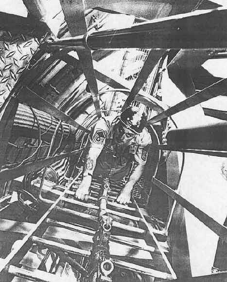
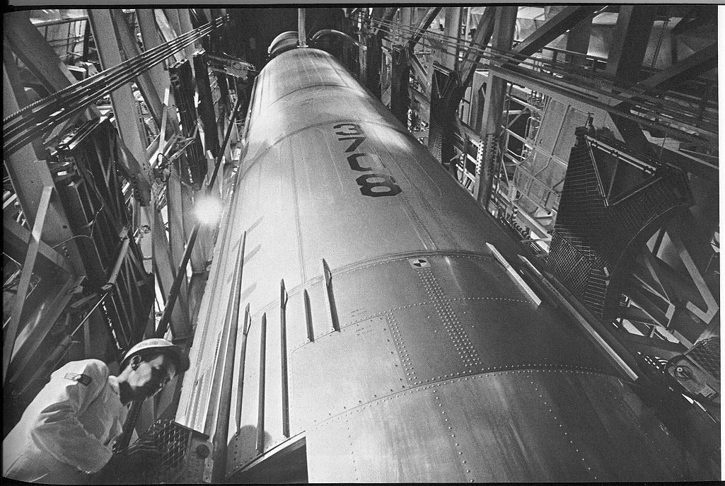
A
sergeant scales a personnel ladder on the missile cribwork. Note
the very large stainless steel wire mesh-wrapped flexible connections
routed through the cribwork at left. You won't find those at your
local plumbing or builders supply retailer.
|
Next
to the missile on the missile platform stands the umbilical
tower. This tower supports and supplies to the missile services it receives from the complex. This includes
power, gases such as nitrogen and helium and
data via microwave channels, all of which were routed through
quick-release connected lines that were severed as explosive bolts
retracted the umbilical tower just prior to lift off.
The
cribwork is a supporting structure much like a cradle and has
maintenance platforms at 8 levels along its vertical length to permit
crew access. A personnel elevator and emergency ladder provide
access to all levels of the cribwork.
|
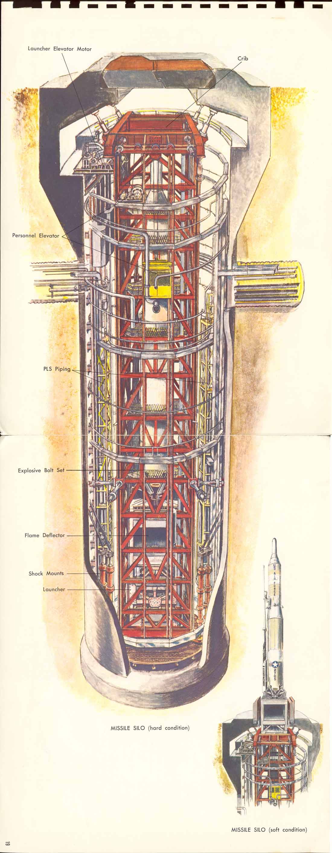
An
excellent cutaway rendering showing most of the features such as
cribwork, launcher and personnel elevators and other equipment now long
gone from most sites. The operational design had evolved a bit
after this picture was created, but it remains a fairly accurate
representation of Lowry Titan sites.
Image
provided by F. Epler.
|
The
launcher elevator system was a cantankerous beast and a source of
continuous consternation for the airmen who manned the Titans.
Manufactured by AMF (American Machine and Foundry) it was said to be
referred to as the "Automatic Mother F*****" among other
choice titles by some of the crews who struggled at times to complete
their exercises with the moody giant. Sometimes it would refuse
to raise the missile to the surface, and others it would refuse to
lower once raised, resulting in a "Popsicle" where the LOX
would have to be boiled off in huge clouds of vapor. Frost would
coat the missile as the terrifically cold LOX rapidly expanded inside
the missile as its temperature rose. As the temperature of the
LOX rose it changed from a liquid back to a gas-- a state requiring
far more space than in liquid form. To prevent bursting the
tanks, valves were opened to allow the gaseous oxygen to escape
safely.
At
other times the launcher system was absolutely dangerous: In the most
spectacular incident a fully loaded missile was being lowered after an
exercise and the braking mechanism of the elevator
system failed (see
page 6 of the linked document)
allowing the missile to crash to the bottom of the silo where it
exploded destroying the missile and the silo and sending one massive
concrete door flying hundreds of feet away and destroying the other
completely. The re-entry vehicle, which I believe contained a
dummy warhead was found in a nearby drainage ditch. No one was
killed or seriously injured in the blast however. I would be
very curious to know if AMF or any other contractors were held liable
for this incident.
The
missile Silos section continues in the next section. Click
below.
Missile
Silos Part II

| Contact
|
Site Map | Links
|
Hosted by
InfoBunker
