|
|
|
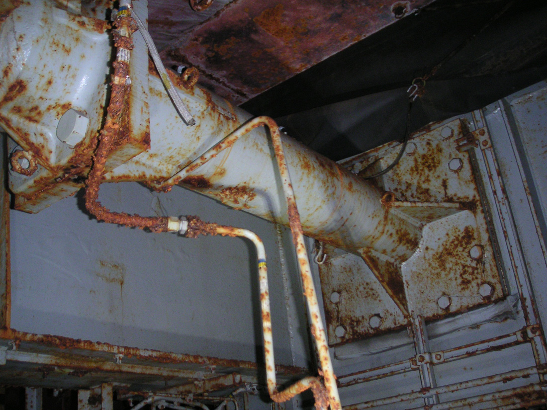
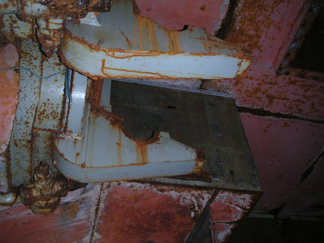
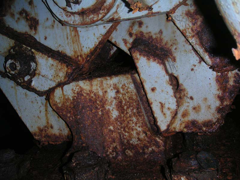
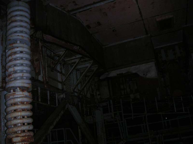
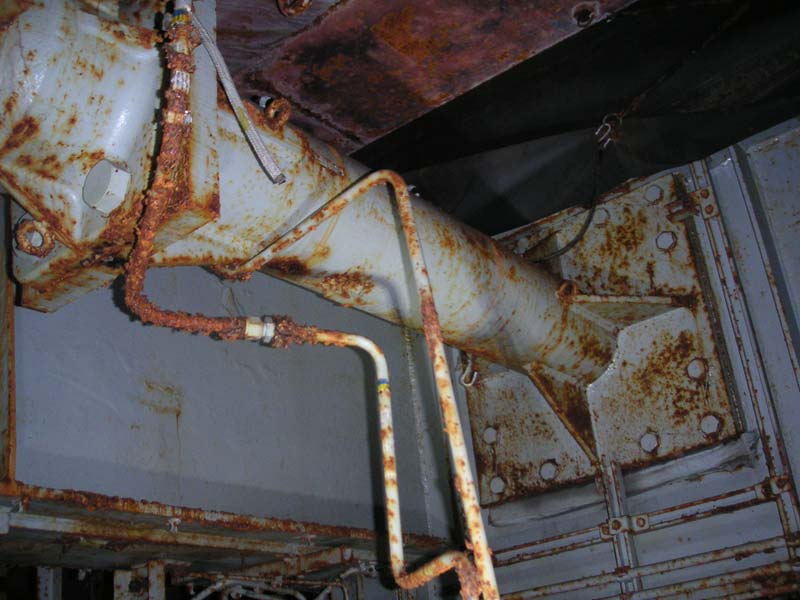
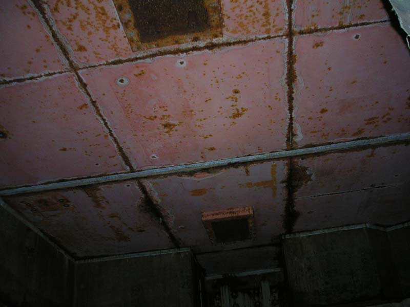
The
curious locking/pivoting mechanism underneath the
elevator motor platform.
|
|
Down
below, hunched over and crab-walking, I saw some strange sights. I
say strange because I couldn't explain it exactly. Under the
platform, I saw this very heavy business that appeared to grip the silo
like some mythical roc with its huge steel talons.
|
|
|
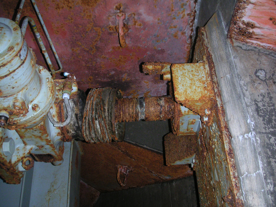
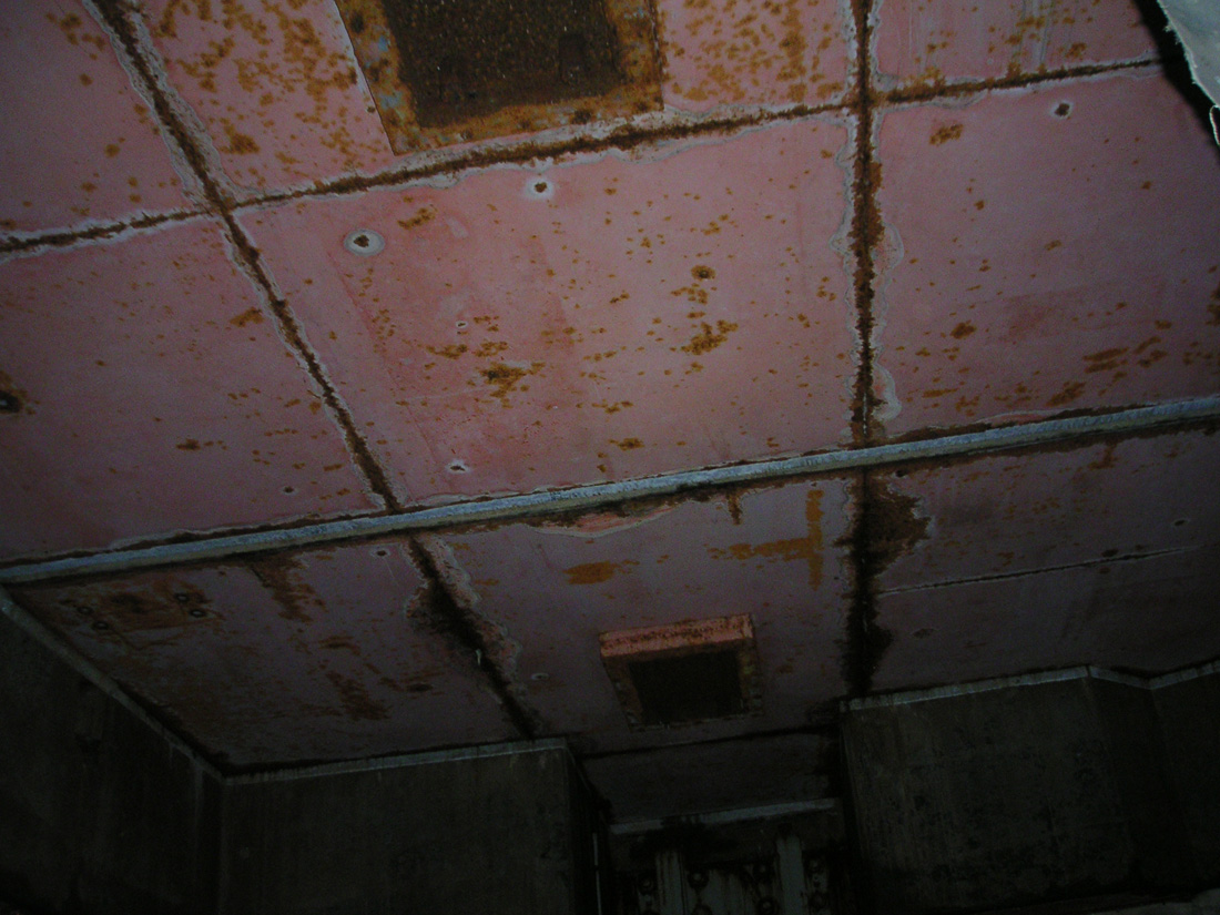
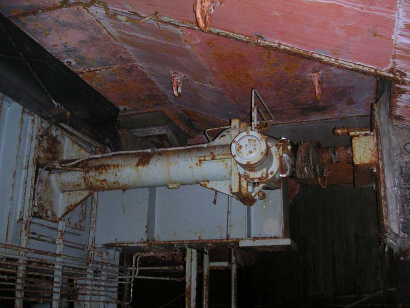
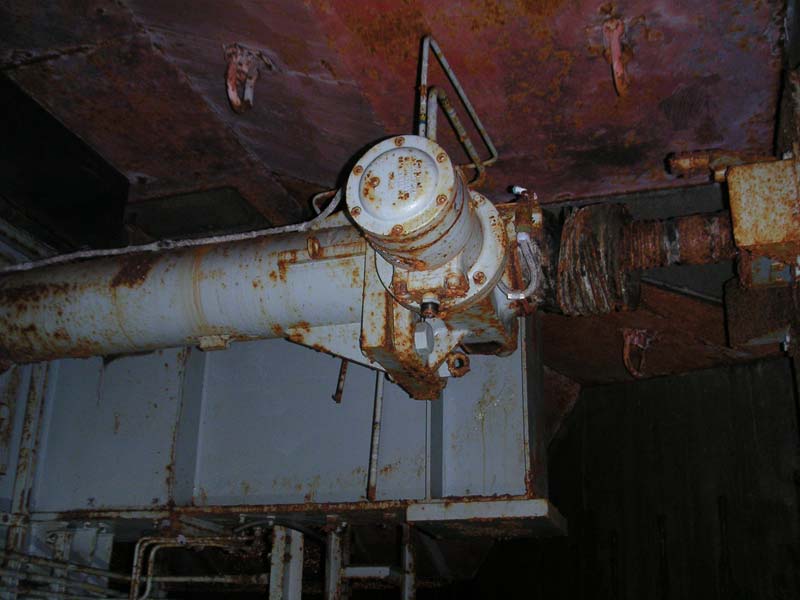
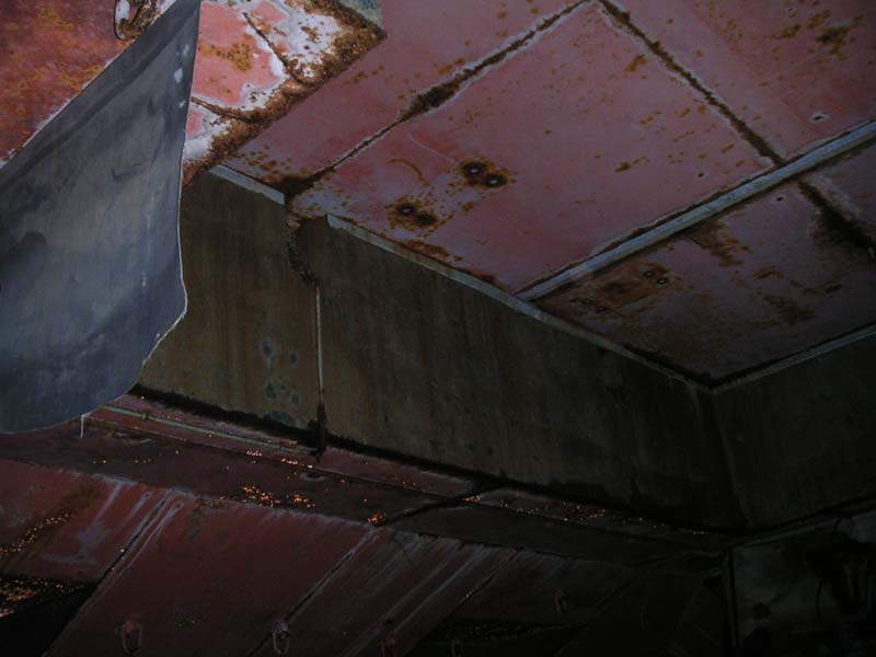
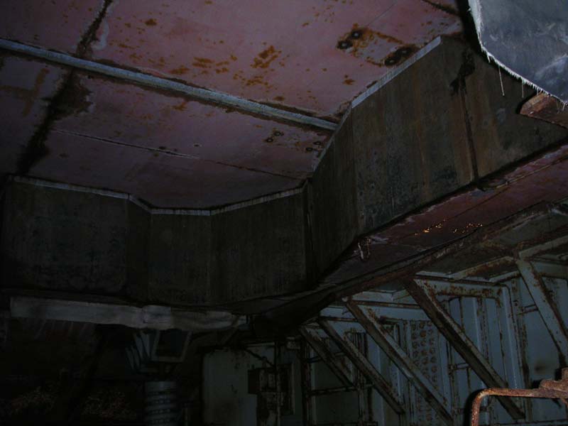
Like
most everything in the Titan I complex, this is also
massive and constructed of very heavy steel.
|
|
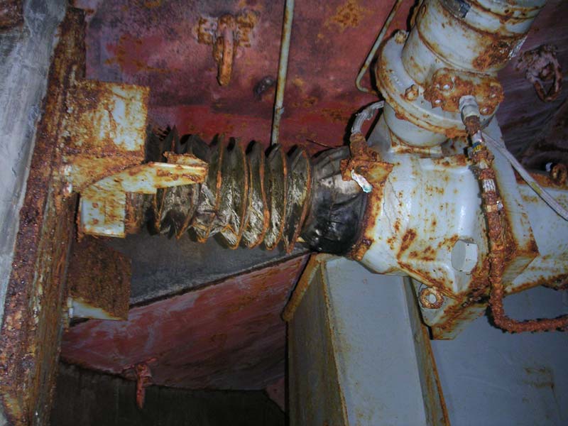
This
set of steel "jaws" or "talons" gripped the silo
very firmly and in fact the entire platform seemed to be held in place
by this odd-looking set of "jaws" that clamped onto (via some
substantial steel mounting points) the
concrete of the silo.
We
had no idea what to call these things that looked like a set of strange locking hinges for the elevator motor platform. We couldn't figure
out why it was designed the way it was. Did the platform
disengage from the silo in the hard condition? (Yes, it turns out.
It did.)
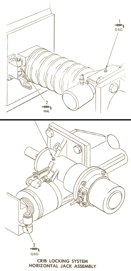
Ever
the curious one, I went hunting through my documents to see if I could
find out what they were called and what their function might be
exactly. Luckily, I dredged up the image below up from my Tech Orders
(T.O.
21M-HGM25A-6-1WC-1PE, Section II - Lubrication Requirements)
which allowed me to at least put a name to these things.
|

|
|
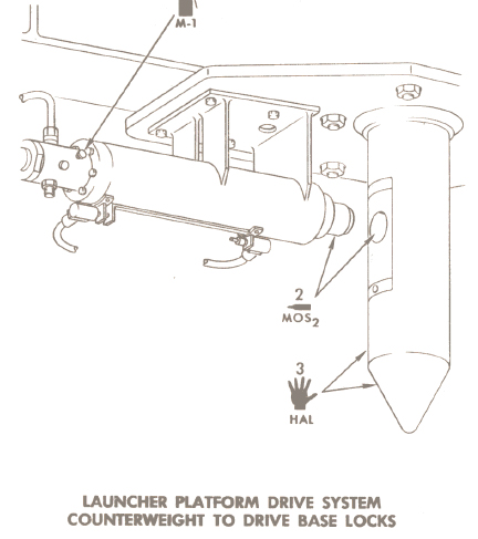
So
there it is, the Launcher Platform Drive System Drive
Base to Silo Wall Rear Locks. I knew that.
Now
what exactly does this thing do?
|
|
Looking
at the diagram I found, there appears to be a linear actuator that locks
the jaws on this thing down tight on the big steel mount on each side
under the platform. My best guess is that before the missile is
elevated, these things bite down and hold the otherwise
"mobile" platform in place as the platform springs provide
some give on the front side while the weight of the missile pulls down on
them. This allows the spring-suspended platform to flex under the
weight of the missile as it is raised or lowered while the locks hold
the pivoting platform securely to the silo.
If
anyone knows better how this system worked, please contact
me and let me know how this complicated mechanism really performed.
We
found some other interesting and curious features under the
platform. There was a lot going on down there!
|
|
|
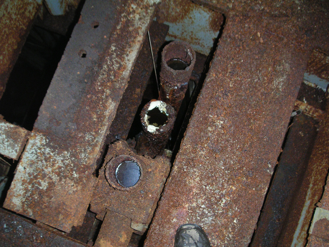
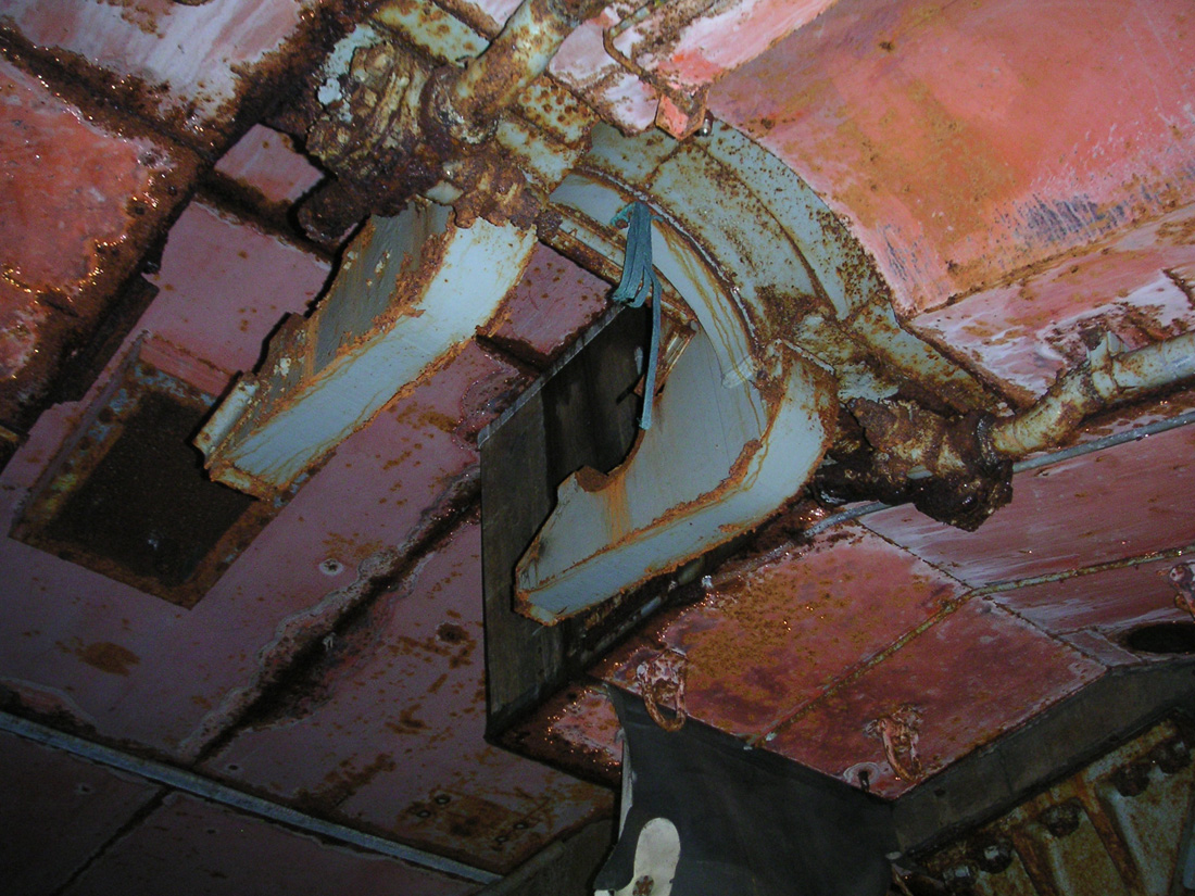
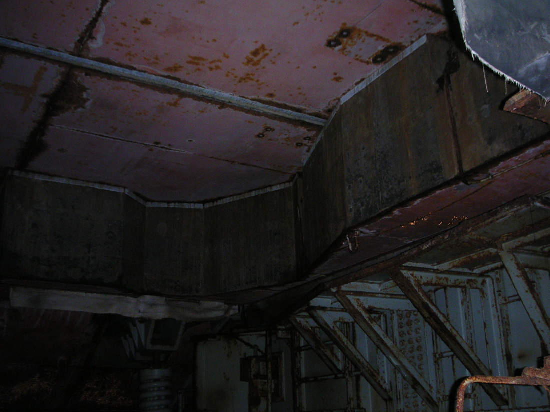
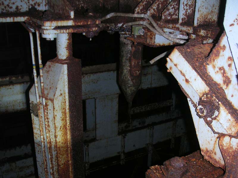
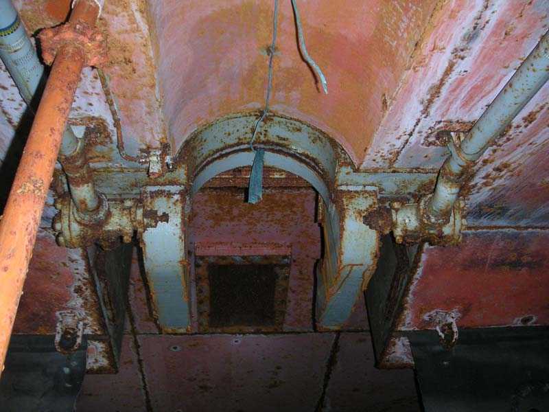
Other
peculiar features under the elevator motor platform, this
huge steel guide pin interfaces with the
top of the counterweights in their fully raised
position.
Left
of the pin is the 3rd object that had us guessing.
What could it be?
|
|
Walter,
having disappeared under the platform before me, brought to my attention
this mysterious trinity of industrial oddities you see above. We
had already arrived at some theories regarding the giant Grippatrons
holding the platform in place, but now these other two items inspired
lively debate.
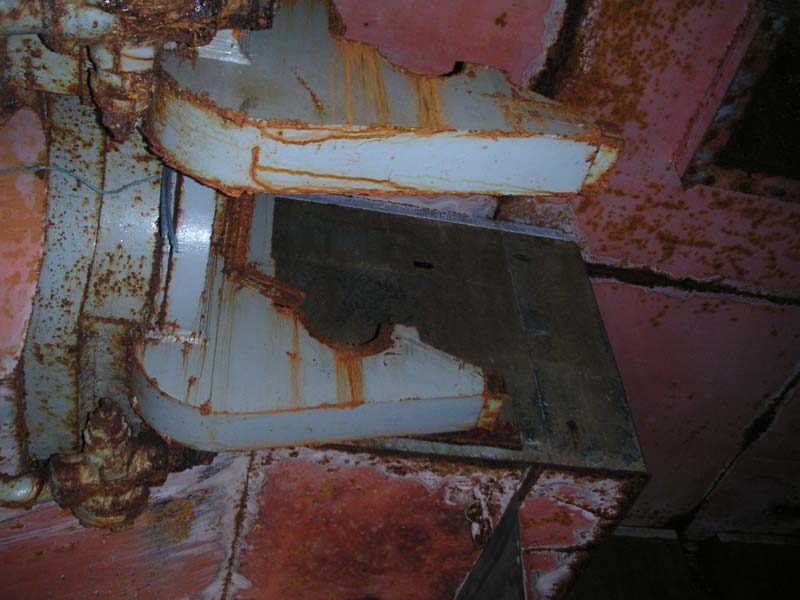
Just
under the overhang created by the platform on which we'd both been
standing was a large and menacing-looking spike (one of two actually) perhaps 4 inches in
diameter. Next to this was a rather monolithic piece of solid
steel that extended up from the counterweight rail to the bottom of the
elevator motor platform.
There
were in fact two of these large spikes and each looked as though each of
the
counterweights would connect to them when they were at the top of the
rail extensions (with the missile lowered in the "hard" silo condition). A
hole in the pins looked to be part of a locking mechanism, though it
appeared parts of the locking apparatus were missing.
|
|
|
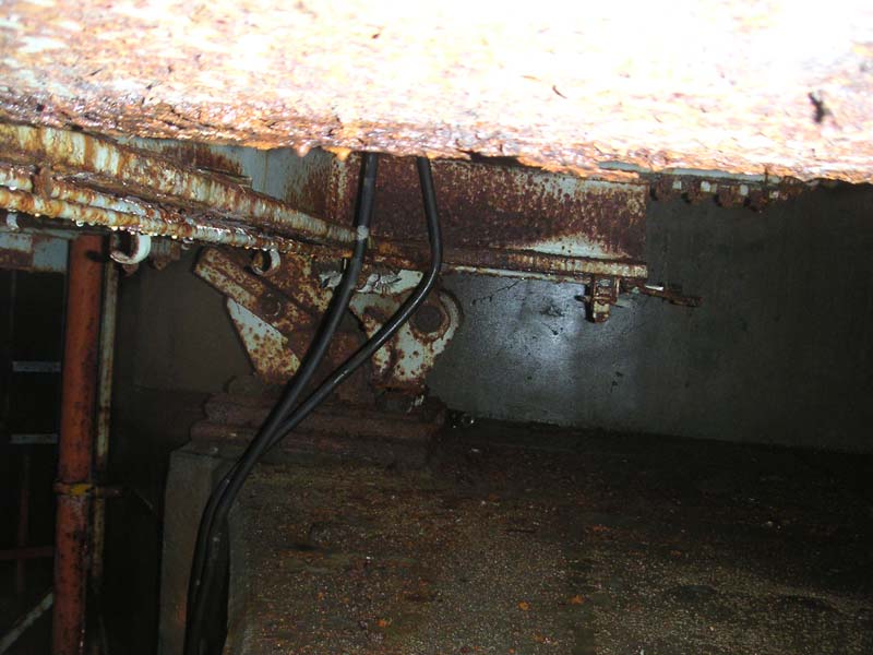
Another
peculiar feature under the elevator motor platform, a
pair of these huge steel guide pins interface with the
top of the counterweights in their fully raised position
and then locks them in place to the motor platform.
|
|
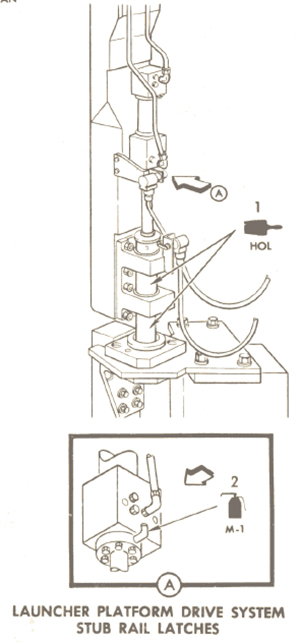
Looking
further at the counterweight rails, we found that this top section of the counterweight
guide rails that had some freedom of movement, perhaps providing a bit
of shock absorption at the top end. Identified as "stub rail
latches" in the T.O. linked above.
In
fact, the entire section was designed to be isolated and supported by
the massive springs of the motor elevator platform in the silo hard
condition.
|
|
|
The
stub rail latches engaged and disengaged the
counterweight rails with a pneumatic pin that extended
to connect the two rail sections. The pin
indicated by 2 arrows in the diagram above extended to
make the physical connection when the missile was ready
to be raised.
|
|
The
illustration above shows how the stub rails interface to the top of the
static guide rails on the silo wall, allowing the counterweights to
travel up onto the shock isolated section which would then disengage
pneumatically leaving the counterweights locked and isolated to protect
the system. Interesting!
The
secrets of the cribwork were being laid bare, piece by piece. I
was never able to make the connections as to how some of the system
worked or was constructed, even though I'd seen pictures or drawings of
some of the parts. Without context or reference, it had all been
very difficult to make sense of.
Now,
things were becoming clear and the fog was lifting. In my mind I
could see how some parts of this huge silo-lift system-- though gone, or
partially gone-- were supposed to function.
|

|
|
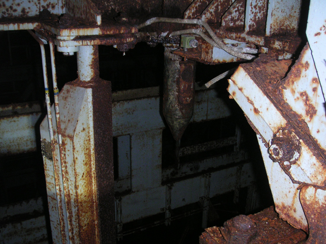
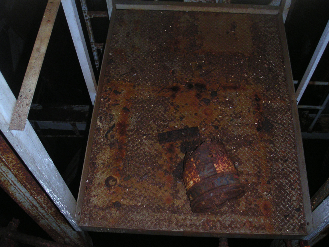
The
precarious platform that hangs in open silo-space
beneath the elevator motor platform. I'd bet money
that rusted little container once held heavy grease for
application under the platform.
|
|
Above
it All
Underneath
the platform, there was a small ladder leading down to a very small
maintenance platform that hung straight down over open air offering an
exhilarating view of the 40 foot drop to the water below. This
platform was there for the express purpose of working on the guide pins,
stub rails and locking mechanism we had just discovered. Standing
on the slightly swaying platform certainly made us alert. I'm
certain nothing we did could have made it budge, but no matter, fear
doesn't rationalize that way.
As
the platform was tiny, Walter and I had to take turns being frightened
by it. There was just enough room to turn around really. I
imagined an airmen in his coveralls on that little platform, grease gun
in hand, suspended in mid-air as he works down the maintenance checklist
with his grease pencil, checking off the list as the platform creaks and
sways slightly with his every move. Just one of many interesting areas
the crews would find themselves working with the Titans.
|
|
|
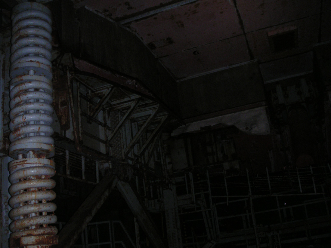
Looking
from the motor platform toward the top of the cribwork
and silo doors overhead.
|
|
Climbing
back up onto the motor platform with its large gaps felt far safer with the
springs' reassuring strength holding me up.
|
|
|
One
of four lateral locking jacks that stabilize the
cribwork for raising the missile and launching.
|
|
The
voyage of discovery continued back at the catwalk that encircled the cribwork at
the very top. There the lateral jacks were just overhead allowing a
close inspection of those monsters which were largely intact, though a bit worse
for wear.
|
|
|
Diagram
of the horizontal jacks. Top shows the jack
extended toward the steel plate on the silo. The end of
the jack had a roller system and the plate used guide
wedges to keep proper alignment.
Bottom
shows the retracted "shoe" with its guide
rollers on the left. A hydraulically-driven worm
gear assembly powered the jacks.
|
|
I'd
only seen these in photos before and it was interesting to note that
they were still extended (and present at all). It makes sense that
they would be extended but the absence of the vertical jacks suggests
that the entire cribwork structure now rests solely on the
gargantuan springs assemblies far below and beneath the water some 100
feet down.
|
|
|
Moving
in for a closer look at the horizontal locking
jack. The structure behind the horizontal jack was
the interfacing support for the vertical jack at this
corner (vertical jack has been removed).
|
|
The
long arms of the lateral jacks reached out overhead to the silo walls at
each corner where the clusters of the three different jacks had once stabilized
the entire cribwork structure.
|
|
|
Closer
view showing the lateral jack base on the cribwork side.
|
|
|
|
|
Large
guide brackets on the silo side where the jack secured
the cribwork against the silo structure.
|
|
|

|
|
The
protective sleeve on this jack has been damaged exposing
the worm drive underneath.
|
|
After
some considerable time (I don't know how much, it's impossible to judge such
things as time in such a place) we neared the end of all that was launcher silo
#3-- at least, what wasn't under water anyway.
Most
of what I saw around the catwalk was familiar from my visits to the
catwalks of the Lowry 724-C launchers. Alas, once again, the silo
door hydraulic rams were gone; most disappointing, but by no means
surprising.
|
|
|
A
semi-circular channel in the very top of the silo cap
where one of the two hydraulic door rams once nestled
when the doors were closed.
|
|
The
mounts for the hydraulic cylinders are just another bit of hardware that
is difficult to appreciate without taking in the sheer mass of the
thing. Each of these "forks" protruding in the photos
are really just the bottom half of the hardware which is a very large
chunk of solid steel, inches thick and capable of supporting tremendous
weight.
|

|
|
Here
you can see at the end of the channel, part of the door
hydraulic ram pivoting assembly projecting outward like
a pair of arms, palms up. The top half that
secured the VERY LARGE ram in place has been removed
allowing the valuable salvage to be hoisted out and
hauled away.
|
|
You
could literally hang a couple passenger vehicles (with passengers!) from these
things like a giant mobile and it would remain unmoved in the slightest.
|
|
|
The
arms-- ever-beckoning for their stolen
hydraulics.
When
all is silent in the dark silo, if you listen closely
you can sometimes hear a faint and ghostly voice calling
for their return:
"Puuuuut
thooose baaack daaammmit!"
Spooky...
|
|
Scurrying
around the last few areas of the catwalk level, it was clear that we'd seen
pretty much all there was to see and now it remained for us to descend the
cribwork and do our best to re-board the kayak without taking a bath.
|
|
|
Looking
up at the inside of the silo doors. You can easily
make out where the terminal ends of the hydraulics were
bolted in place.
|
|
Walter
was first to brave The Kayak Challenge, the plan being that once he'd given the
kayak a bit of draft, I would be less likely to take a camera-killing plunge as
I tried to board.
I
managed to stave off disaster and took my damp seat on the kayak just as
my trousers had dried off somewhat. As the chill seeped into my
undergarments once more, we cast off from the rusted "pier"
and charted a course back to the entrance.
|
|
|
Another
view of the inside of the doors showing the torn
environmental seal, made of a very tough rubberized
fabric, hanging at the left of the picture.
|
|
Back
on the surface, we caught some much-needed warmth in the sun, gulped some much-needed
water and had a few more chocolate donuts that had remained disturbingly
un-melted after hours in the heat of the car.
My
camera, though drier, remained disappointingly destroyed, though I still
held out hope it could be revived.
|
|
|
One
last peek at the silo doors, looking toward the
irregular-shaped portion of the silo opening that made
room the umbilical tower when the missile was raised to
the surface.
|
|
We
soaked up the warm sun like two lizards and then trundled back to the
underground kayak landing. We had another silo to explore!
Tune
in soon for the next installment: