|
|
|
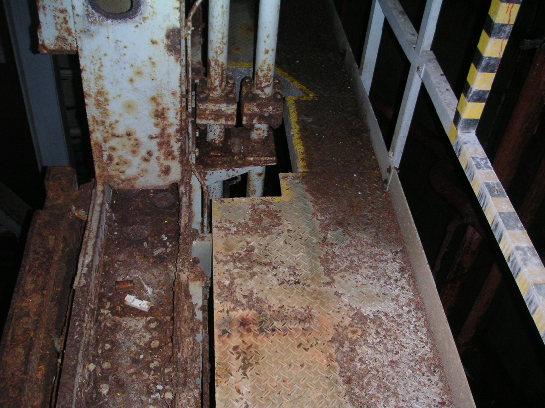
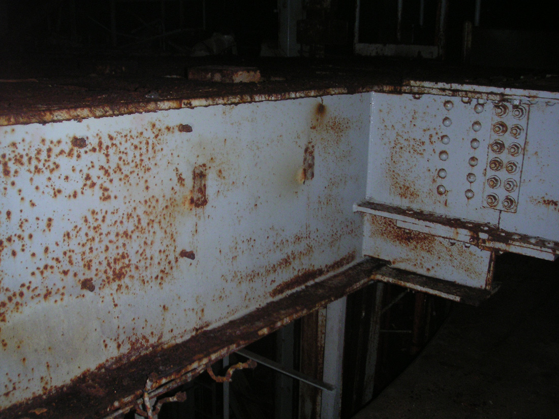
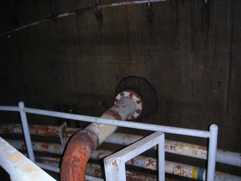
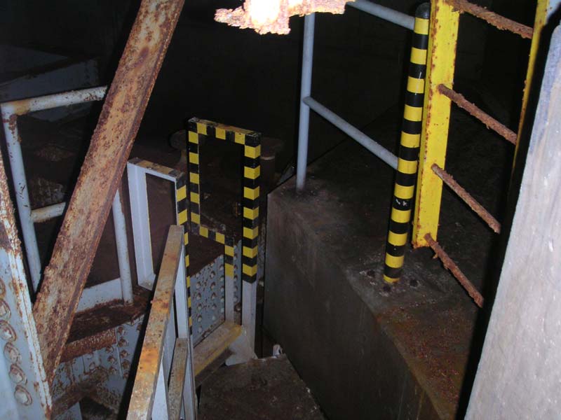
Looking
down at the spot shown in the previous photo from the
catwalk level of the silo.
|
|
The
Upper Regions
Scaling
further, we reached the final series of catwalks and access ladders
where the landscape became far more conducive to traipsing about without
the uneasy feeling that death lurked uncomfortably close at hand,
sharpening his scythe.
|
|
|
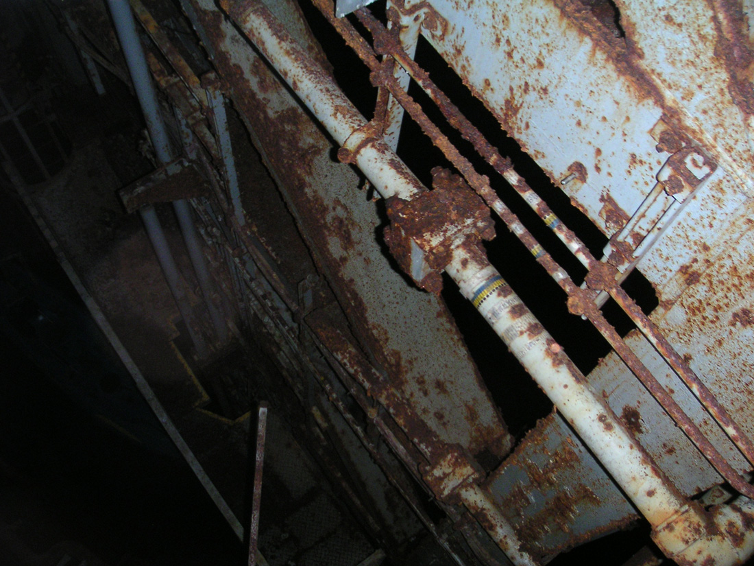
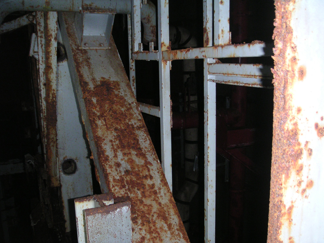
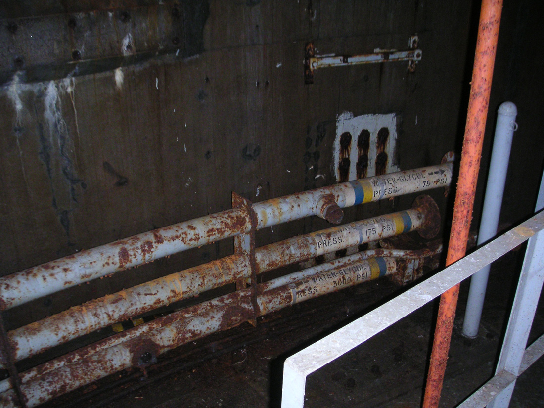
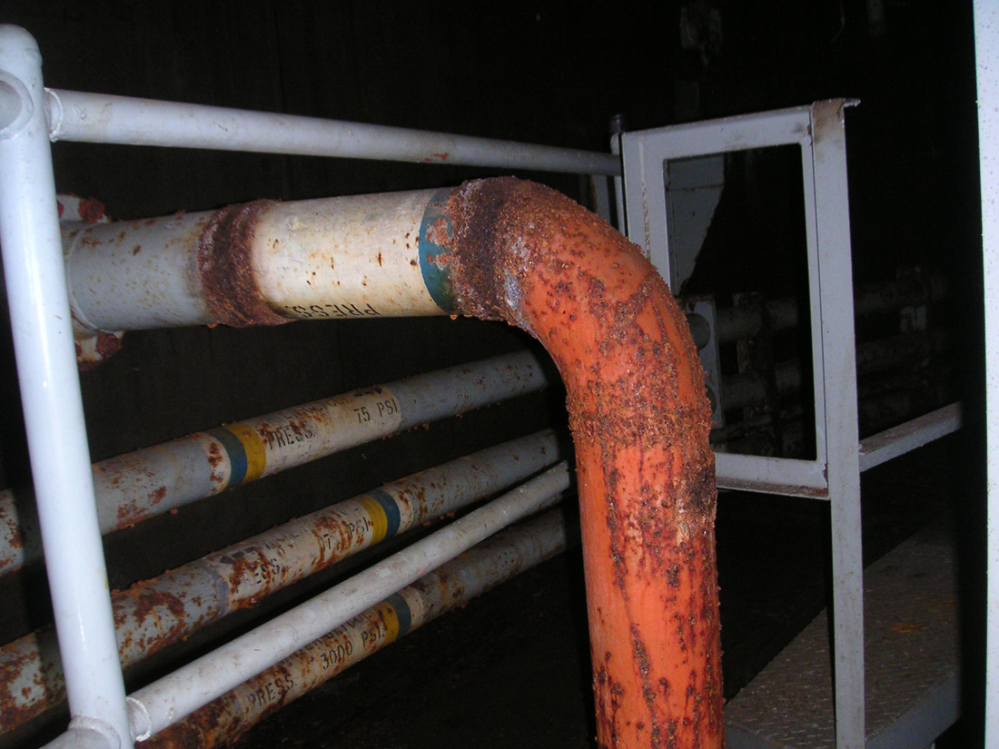
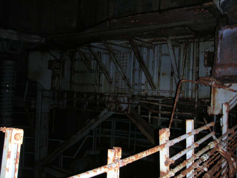
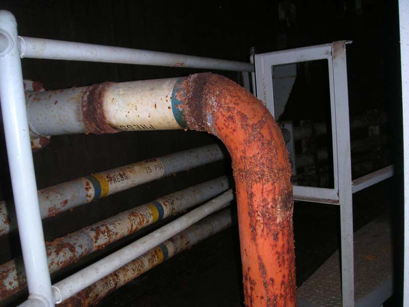
Walkways
and hydraulic lines abound at this face of the cribwork
near the very top. The small lines pre- sumably
supplied power to the folding mainten- ance platforms
and crib locks.
|
|
Here,
the world became very hydraulic as the large pipes split, teed and
reduced to thin capillaries that perfused the many fluid-powered work
platforms, jacks, valves, locks and other mechanical assemblies rife in
the area.
To
look at all the hydraulics alone, the amount of man-hours that it must
have taken to install just those services was daunting and one
imagines months of labor being done by crews in the cramped and
restrictive spaces of the silo cribwork.
|
|
|
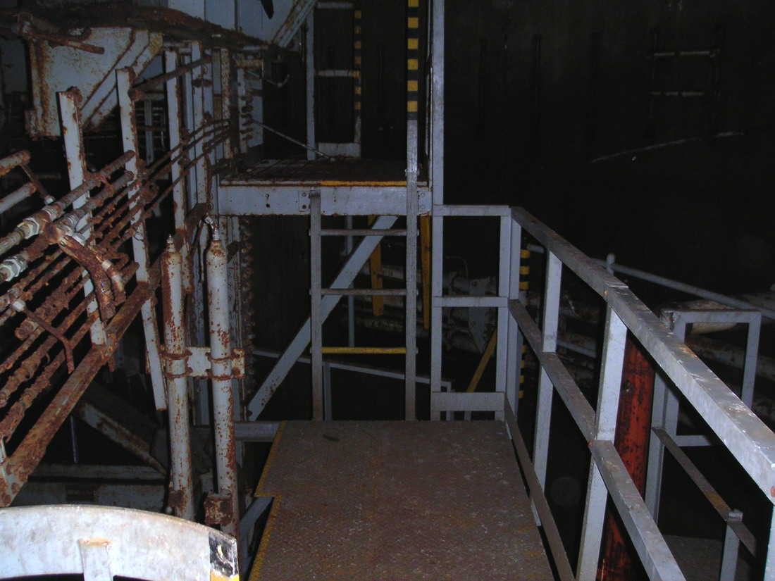
Looking
through a huge gap cut through insanely- heavy
steel and out over the open silo at the steel
structure across the void.
|
|
These
little pipes were the purview of just one of the many trade disciplines
called upon to complete work in this area. Coordinating all of them so
that they had room to move must certainly have been a challenge.
|

|
|
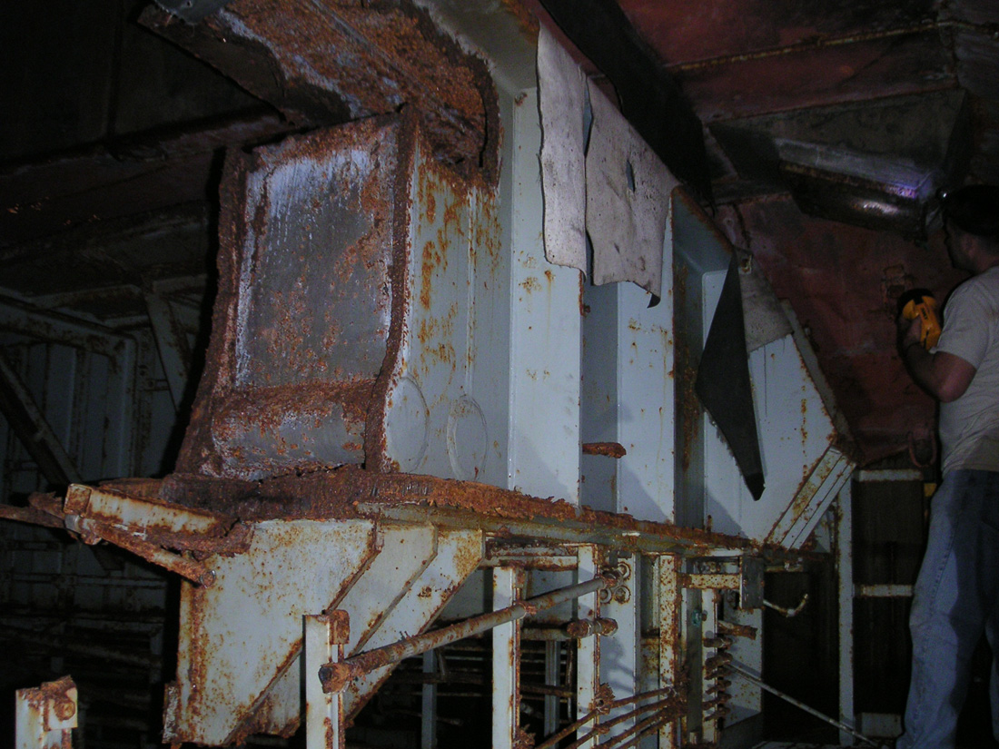
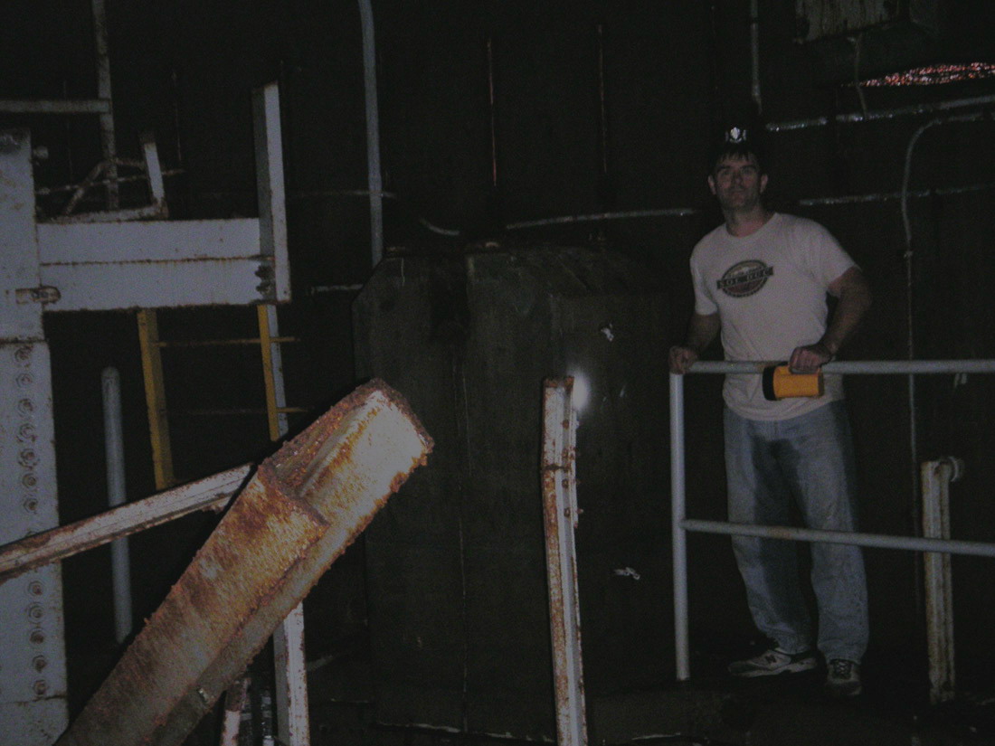
Here
you can see the gap mentioned in the previous caption
where a heavy cutting torch has taken a Godzilla-sized
bite out of the heaviest and topmost structure of the
cribwork. I can only assume this was done to make
salvage possible, but I can't fig- ure out what was
removed here that required such an effort. That's
Walter there inspecting one of the stabilization
assemblies.
|
|
The
last time I had been in the silo cap area was way back in 2003 when I scaled
the walls of 2 silos at 724-C without the benefit of any cribwork or
sensible safety gear. (not recommended, really)
Back
at 724-C there had been no cribwork of course and what remained in the
silo left a lot to the imagination. Still, there was a lot to see
and since it was all new to my eyes I was certainly not disappointed.
Now,
as we neared the very top of the silo, with the cribwork in attendance,
there was essentially a whole new world of details and structures I'd
never clapped eyes upon.
|
|
|
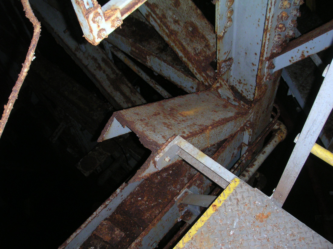
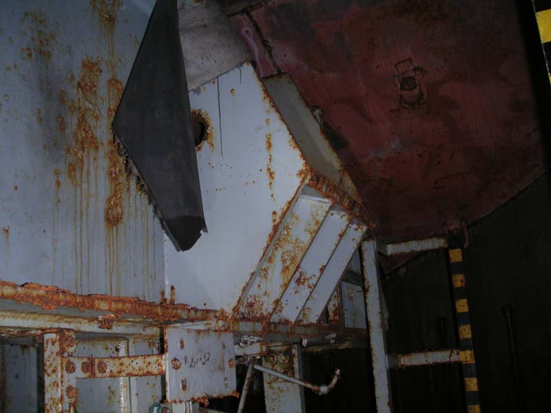
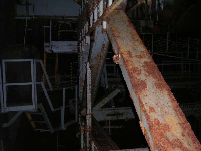
Looking
at more heavy metal. This is the top beam
structure of the cribwork, it extends to just about 2
feet of the concrete of the silo cap-- the top of the
launcher silo.
That
heavy steel outcropping near the center of the photo is
where one of the inclined locking jacks was mounted.
|
|
|
|
|
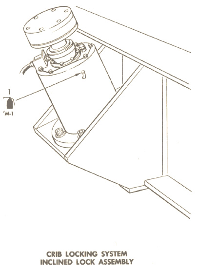
Diagram
of the inclined locking jack
|
|
Tip
Top
With
the red primer-colored ceiling just over our heads, Walter and I
set about to trying to make sense of all that we saw.
|
|
|
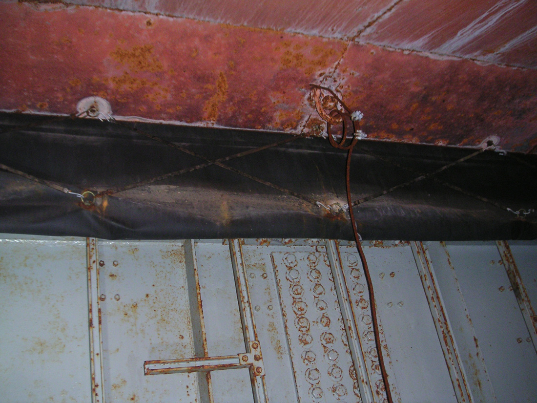
An
intact portion of the heavy environmental seal around
the mouth of the silo, covering the gap between the
cribwork and the silo cap.
|
|
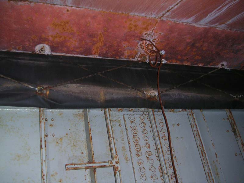
Though
technically "floating" on a suspension system of springs
within the silo, the cribwork turns out in fact to be attached to the
silo cap by an extremely tough-looking weather seal that spans the gap
between the crib and the ceiling of the silo cap.
Prompted
by a hanging tatter of rubberized fabric, a bit of scrambling about on
the steelwork provided a better look at just what was involved with this
new discovery.
|

|
|
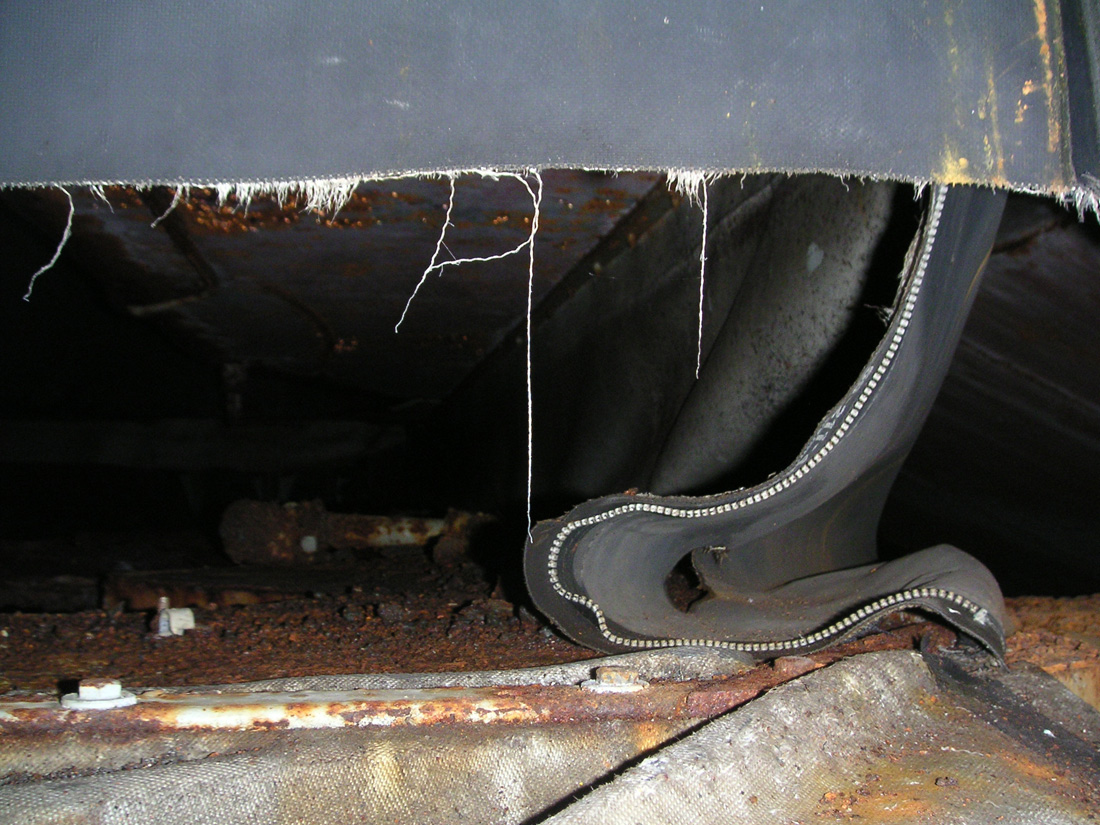
A
torn section of the environmental seal showing a
zippered section. You can see here where the top
edge is riveted to the concrete around the lip of the
launcher opening. The seal's very strong fabric
has been torn along the zipper during salvage,
suggesting
the cribwork was significantly disturbed during the
process.
|
|
We
took turns climbing up to gaze at the extreme top edge of the cribwork steel
viewed through a gap in the damaged weather seal. There was saw
accumulated rust from decades of corrosion and bits of steel, bolts and other
debris left by salvage operations.
Looking
at the seal itself, we could see it had suffered damage during some
pronounced disturbances to the disposition of the cribwork. I
could only imagine what salvage work had displaced the cribwork to rent
that tough membrane to such a degree: a swaying elevator motor being
hoisted out of the silo's mouth; a giant leaden counterweight; an
irregular bundle of stainless pipes, rotating as it rises, trailing tag
lines and knocking against the crib at intervals... Who knows?
|
|
|
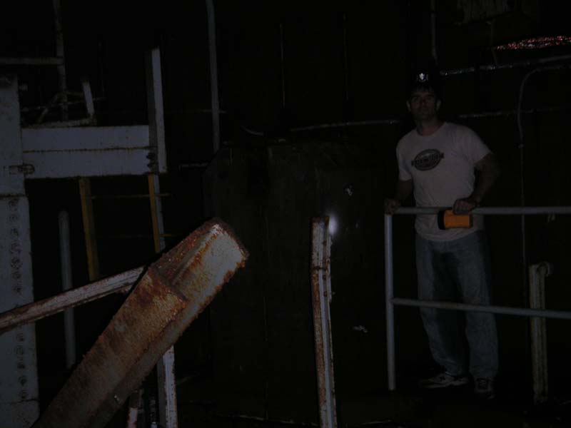
Walter
on the catwalk near one of the vertical jack support
blocks. Another severed beam protrudes into the
frame.
|
|
This
weather seal is riveted to the concrete ceiling on one end and bolted to the
steel on the lower end. It is buffered by a web of bungee-like cords
that criss-cross over its face, steadfastly defying their age by staying taut
over the ensuing decades.
There
on the seal we see the biggest, most rugged-looking zippers I've ever
seen holding sections of the seal together. We marvel at these a
bit before being distracted by larger structural features.
|
|
|
Looking
along the outside of the cribwork toward the vertical
jack support where Walter was seen stand- ing in the
previous photo. The catwalk routes around the
support block with a detour on the inside of the open
silo-- a feature that can be a bit un- settling the
first time through.
|
|
|
|
|
Standing
on a small maintenance platform near the cut off
beam. That steel is heavier than it looks in this
photo, trust me.
|
|
|

|
|
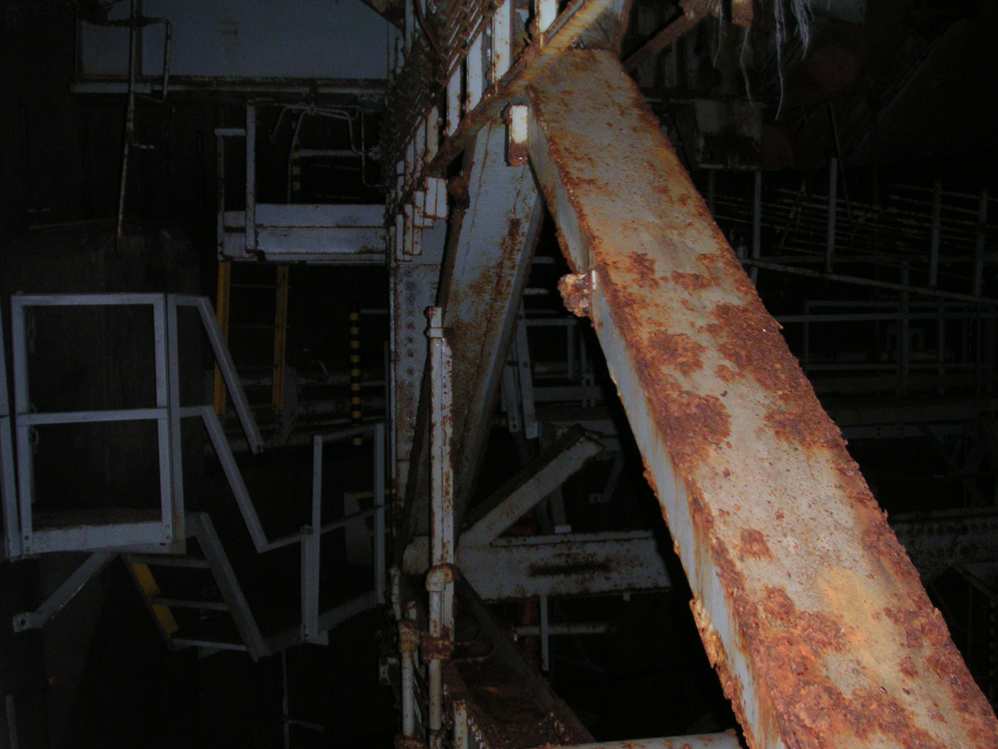
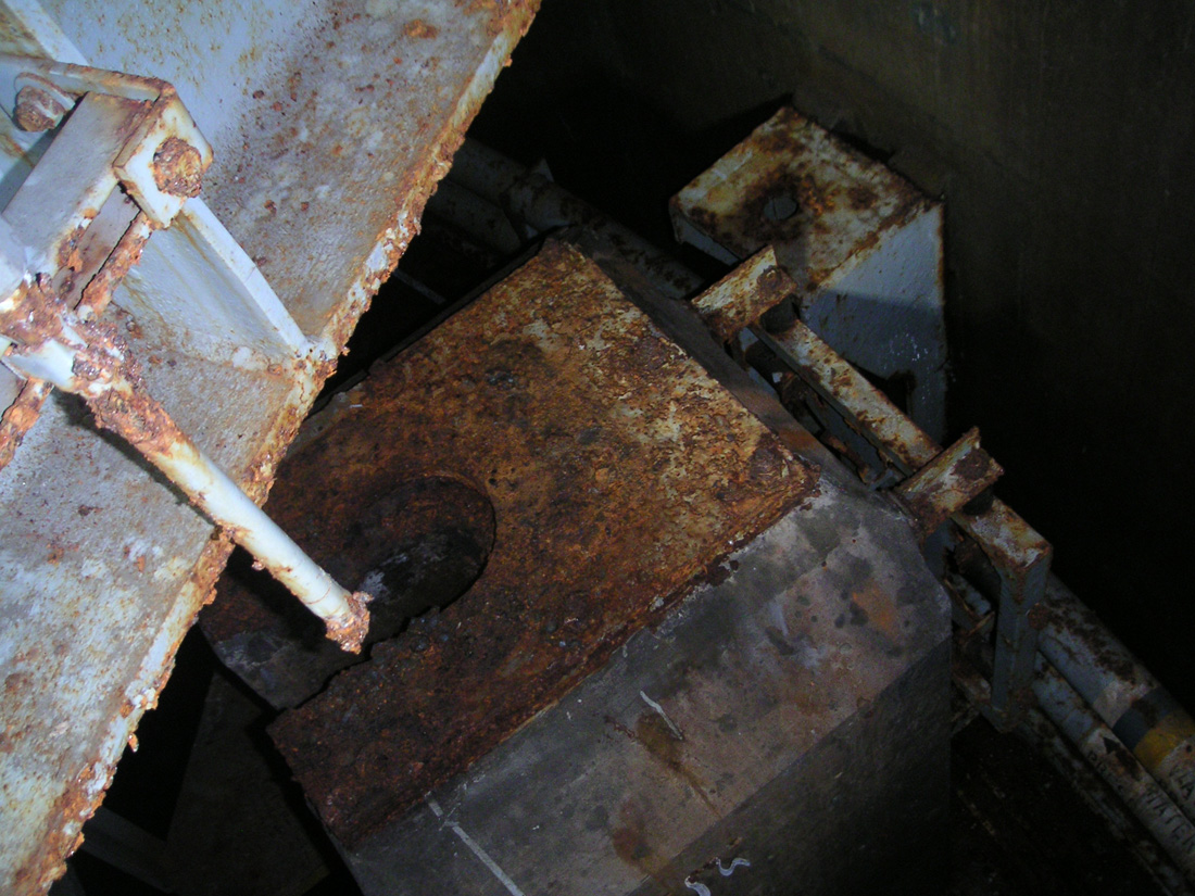
Another
chunk of steel removed during salvage. It must
have been in the way of something they wanted.
|
|
|

|
|
Cross-sectional
view of one of the many chopped-off I-beams in the
cribwork. That steel is about 1.5 inches thick.
|
|
All
around the silo cap, we see hydraulic lines running everywhere: on the
walls, on the floors, up and down the cribwork beams and everywhere in between.
These lines serve valves, actuators, service platforms and many other
pieces of this complex construction that is the launcher system.
Now
that we were at the top of the cribwork, could see a bunch of these hydraulic lines running to the very top of the structure to service the
locking jacks.
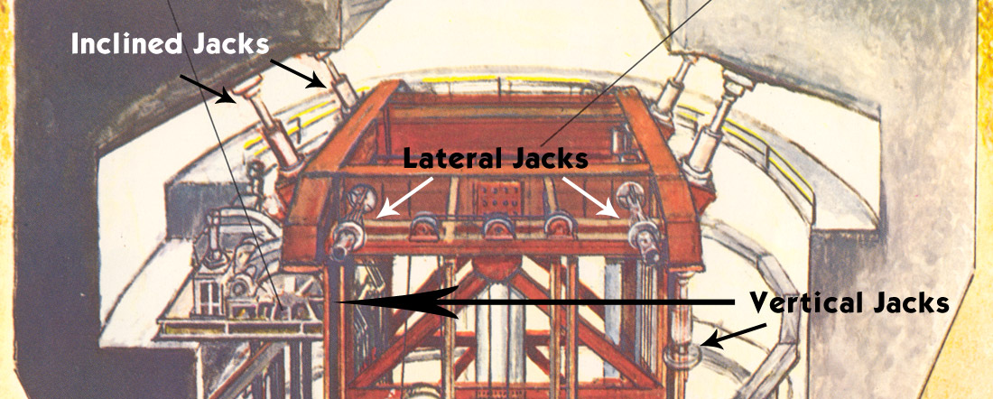
To
secure the cribwork for launch, it was stabilized by a series of locking
jacks that held the entire massive framework steady to the silo
structure. These jacks would extend outward to or from the cribwork
(depending on which type of jack) to press against the interior of the silo
and firmly hold the entire structure in place. There were three types of of these jacks to prevent movement
in any direction:
1.
Vertical - One at each corner (see next image and photo below)
2.
Lateral - Two on one side and two on the other
3.
Inclined - Two on one side and two on the other at an angle of
perhaps 30 degrees off vertical.
|
|
|
Illustration
showing the various locking jacks and their
locations. The vertical jack indicated on the
lower left is not visible in this partial cutaway, but
its position is refer- enced by the large arrow.
|
|
|

|
|
Looking
down at the top of one of the vertical jack
supports. All the vertical jacks have been removed
at 568-C along with the inclined jacks, but the lateral
jacks are still in place as you'll see in the next section.
Pictures
of the vertical jacks can be seen in section
IV
and section
V
of the missile silos.
|
|
|
|
|
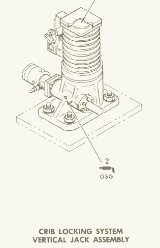
Diagram
of the vertical jack. This is a simple hydraulic
drive with a worm gear that extended the jack to the
silo cribwork.
|
|
|

|
|
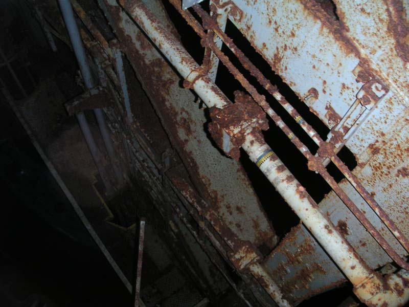
Hydraulic
lines on the catwalk level. These very large lines
power the silo doors.
|
|
All
these smaller lines were broken out at manifolds from hydraulic mains
that encircle the silo cap. From the manifolds the hydraulic lines
extended out to the jacks and platforms and from the largest lines to
the silo doors.
Just
as I had seen at Lowry 724-C, these lines were left behind, apparently
not valuable enough to warrant the trouble required to cut them out and
haul them away.
|
|
|
Silo
sump discharge line. This runs to the surface
where it terminates at a seal chamber-- a concrete box
with an open slot where the water would simply flow out
onto the ground and away from the launcher.
|
|
Walter
headed around the other side of the silo cap as I marveled at the undamaged
silo discharge line, still attached to the silo wall.
|
|
|
Another
shot of the silo sump discharge line. Exciting, I
know. Usually when I see this, it's been torn
loose from the silo wall during some rather violent
phase of salvage operations in the silo. It was
nice to see one intact, silly as that might seem.
|
|
This
particular feature seems to have failed to survive the removal of the
cribwork at all the other silos I've seen firsthand so far. Since
it extends to the very sub-floor of the silo were the sump pits are
located, some part of it always seems to get violently knocked about
during salvage operations on the silo cribwork. You may recall
from section IV and section
V of the missile silos that I observed uncannily similar damage to
the sump discharges at those silos-- damage I didn't see here.
|
|
|
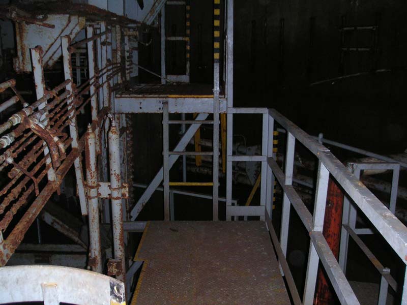
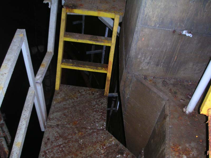
More
precarious footings around the vertical jack
supports. I know that's all steel, but somehow it
just looks insubstantial and cheap when I start walking
over it.
|
|
Though
this silo seemed in far better shape than those I saw at 724-C, I still
trod lightly on these flying platforms and spent very little time
standing on them. It wasn't absolutely necessary to use them, but
encumbered as I was with cameras, backpack and lights, I felt I risked
fewer incidents of loss like the one experienced
earlier with my ex-camera by not scrambling up and over the pipes
that blocked the catwalk.
|
|
|
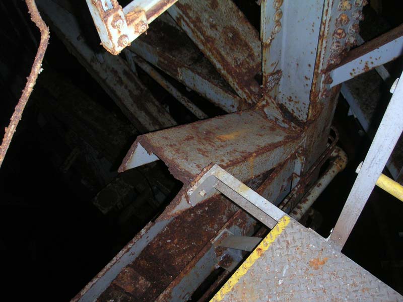
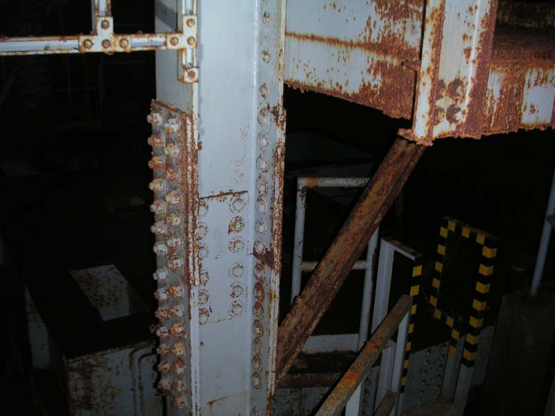
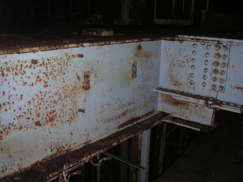
A
big join in two big, big I-beams at one corner of the
cribwork and looking in the direction of the elevator
motor platform.
|
|
When
we climbed up to the very top of the silo, we were at the opposite side
from the intriguing and enticing elevator motor platform. As we
obsessed over the other sights of the silo, we were both working our way
to the opposite side, saving the best for last. Walter took one
approach and I took the other, effectively cutting off any chance that
it might escape!
|
|
|
Moving
around another vertical jack support toward the elevator
motor platform.
|
|
As
usual, I got there last due to my photographic and video handicaps, but
how could I rush? I was totally enthralled with all the new things
there were to see! Over near the elevator motor platform I could
hear Walter's footsteps crunching on the rusty steel as he cautiously
moved to the edge.
A
deep booming splash from below followed, echoing throughout the silo
seemingly without origin. Then another, and another. Walter
had found some junk to toss into the silo and now I was itching
to do the same.
|
|
|
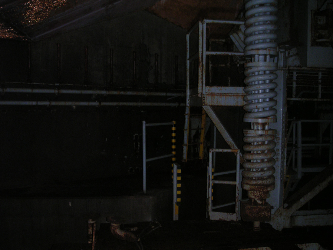
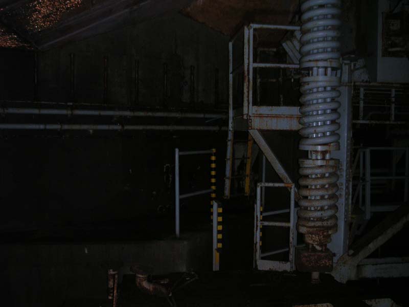
Standing
in a space behind the elevator motor platform. The
whole thing is hinged and was designed to move under
load both as suspension (presumably) and to protect it
from shock.
|
|
I
circled around to the ledge by the platform and climbed up, eager to peer over
the edge into that dark, scary void that I knew waited below.
Once
I had gotten that out of my system and tossed a few bolts and other odds
bits of steel into the water, I turned my attention to something else I
found irresistible: these giant springs that held up the whole platform!
|
|
|
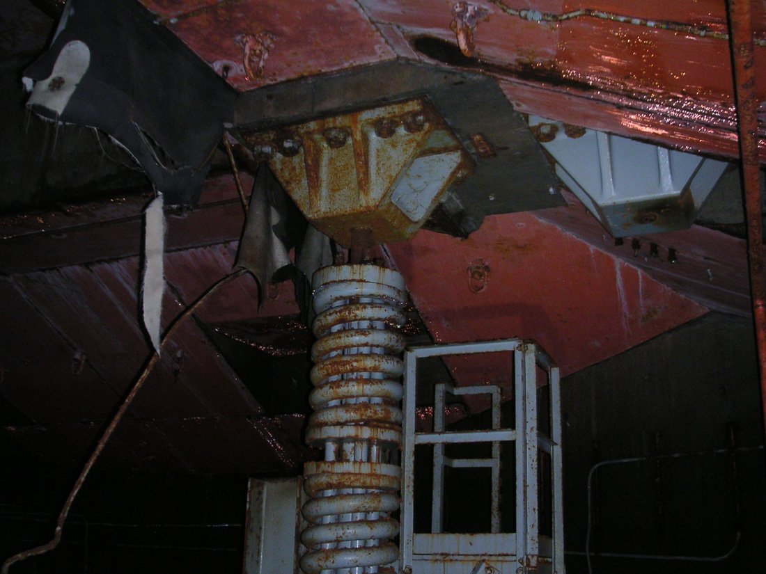
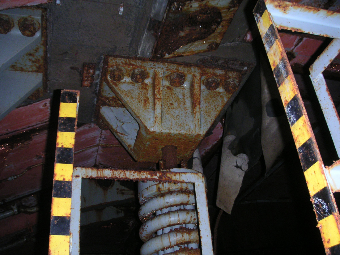
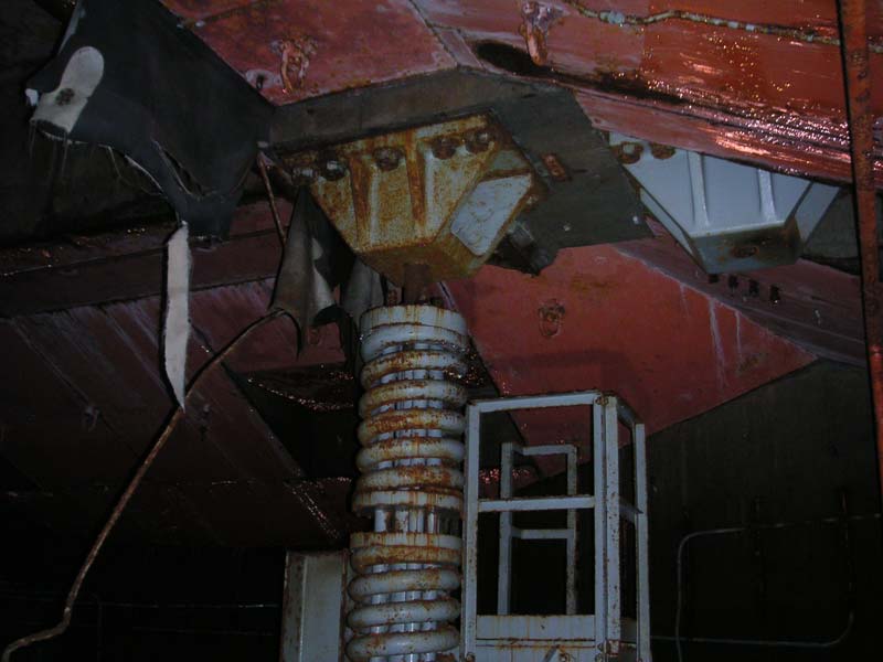
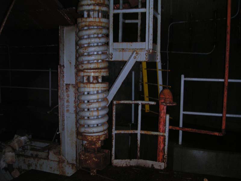
Standing
on the elevator motor platform and looking at one of the
enormous spring assemblies that supported it.
|
|
Spring
Is Here!
I'd
never seen anything like them. These springs could only be
compared to the photos I'd seen of Cheyenne Mountain (AKA: former NORAD)
showing the massive springs upon which the entire inner sanctum
of that place rested.
|
|
|
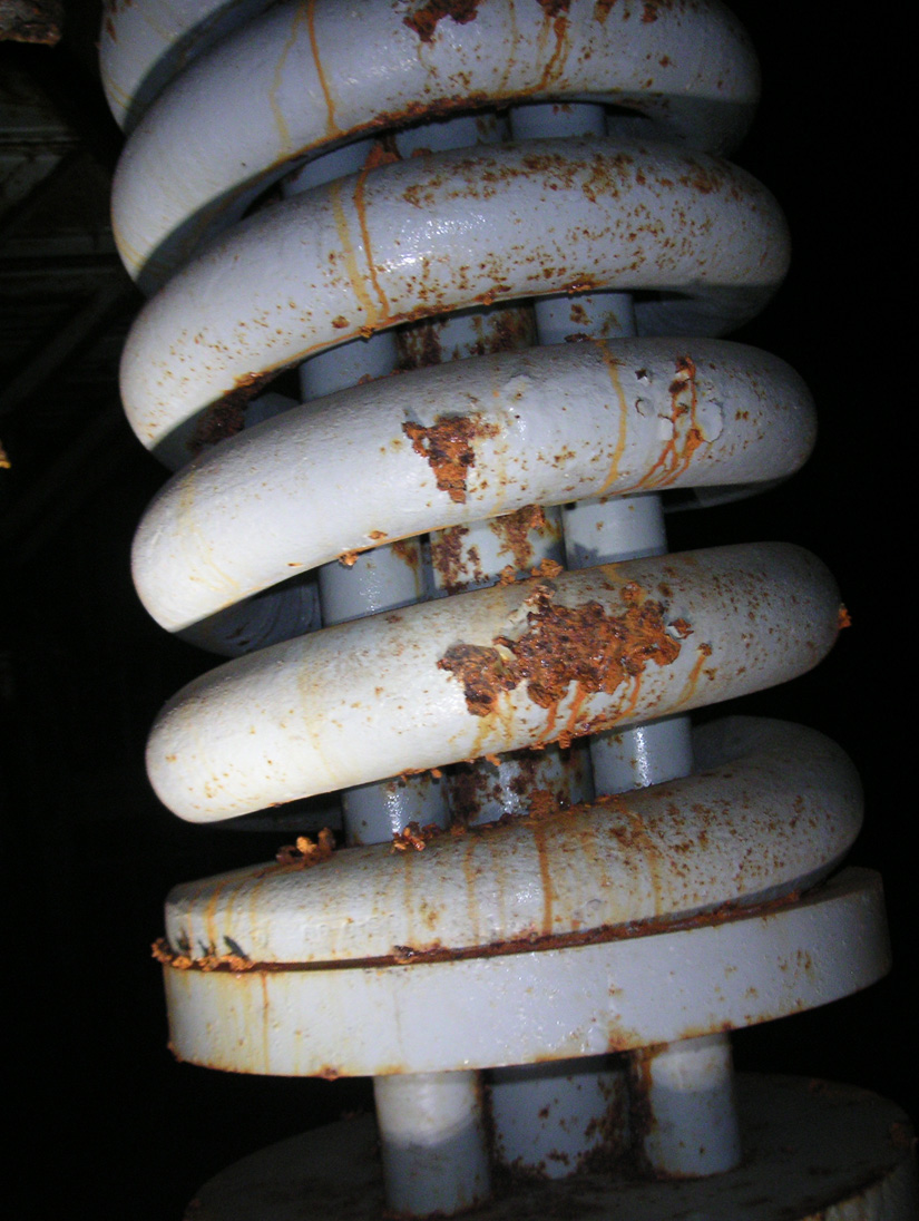
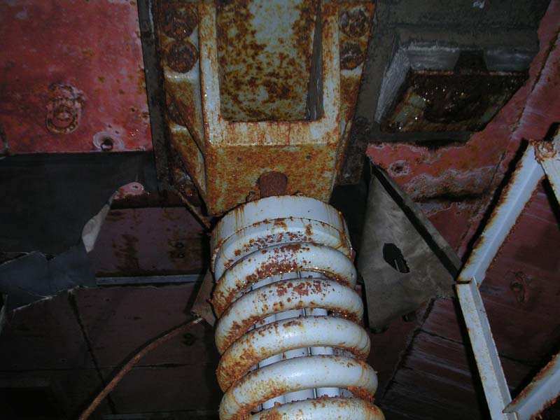
Looking
at the springs' supports, bolted to the ceiling of the
silo cap with 10 nuts, each of them larger than my
fist.
Note
that one spring has been remove on this side.
|
|
I
couldn't imagine such springs ever flexing. I would imagine you could
stack a truck or two on that platform and not see much movement out of springs
such as those.
|
|
|
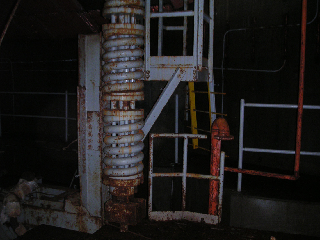
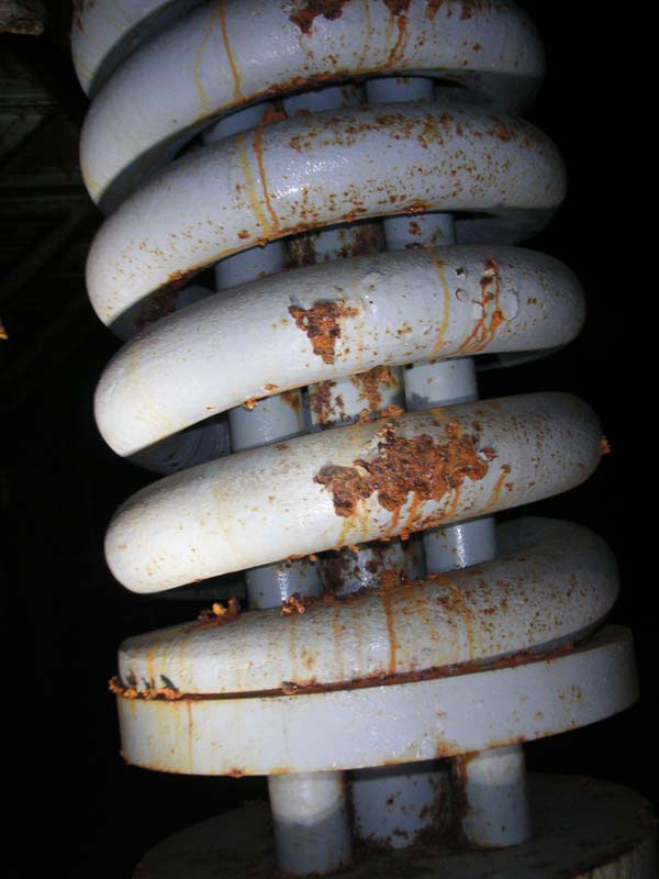
I
thought these springs were pretty impressive so, yeah,
there are a lot of photos of them. I honestly wish
everyone could see for real just how big these things
are.
|
|
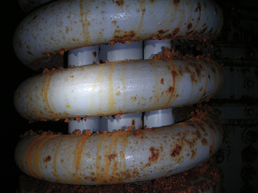
No,
I don't think you get it. I don't think you've grasped the monolithicity
(yes, I just made that up, I think) of these springs. They.
Are. HUGE.
|

|
|
Looking
at the enormous bracket that supports the spring
assembly.
|
|
Oh
sure, in these photos, they may not look that big, but I think that the impact
is lost in the translation. Look at that bracket from which the spring is
suspended. Take a good look.
|
|
|
Moving
in for a closer look...
|
|
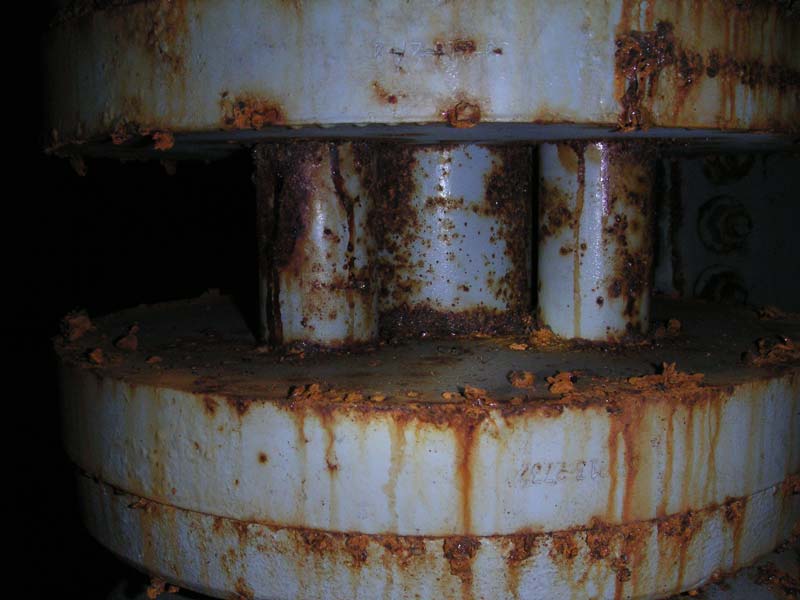
See
those nuts holding up the whole affair? Each of those bloody
things is just a bit bigger than my fist (which isn't dainty by any
means) and there are ten (10!) of them holding each one of these springs
up by a steel bolt nearly 4 inches in diameter!
|
|
|
Closer...
|
|
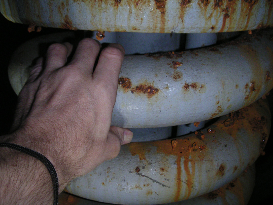
What's
that? Two and one-half inches doesn't sound like all that much you
say? Well, let me know when you can bend one by ANY means and
perhaps I will stop being incredulous about your lack of
incredulousness.
Who
makes these damn things anyway? Oh right, AMF did. I knew
that. That's the "F" part of American Machine and
Foundry.
|

|
|
Closer
still, but a sense of scale would be helpful now.
|
|
The
missile, fully loaded weighs well in excess of 100,000 pounds, which is over 50
TONS of mass-- well, in fact, none of that really matters. Just
trust me, if you could stand right there next to one, you'd be impressed.
|

|
|
Yes,
that is about 3.5 inches in diameter. Insane!
|
|
|
|
|
Ok,
last couple pics of these, honest!
|
|
|

|
|
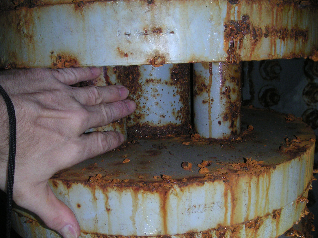
Don't
get your hand caught in one of these.
|
|
More
cribwork to come as we peer into (and under) more hidden-away areas at the
top levels of the silo.
Tune
in soon for the next installment: