Construction
photos of the equipment terminals proved fiendishly rare and I don't have
much to offer from that part of the history of the Titan I, or from their operational period
for that matter. What I do have
is almost all provided by Mr. F. Epler from his extraordinary collection,
without which this site would be greatly diminished.
|
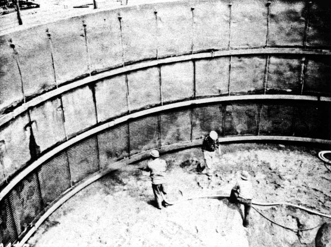
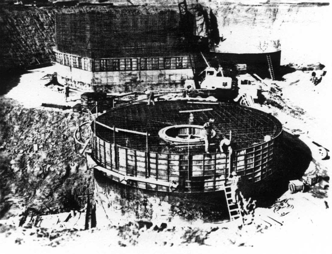
Bottom
of an early equipment terminal's construction. Workers applying
gunnite (sprayed concrete) to the inside walls. Several more
concrete pours are yet to be added before the walls of this equipment
terminal will be complete.
Photo
courtesy of Fred Epler
|
Like
most of the Titan I complex, the equipment terminals were constructed
by excavating the site where a given structure or structures were to
be built and then back-filling and compacting soil around the finished
construction once it was complete.
This
method was used in nearly the entire site with the exception of a few
of the vent shafts and the missile silos. Some vent shafts were actually
drilled with auger-type boring equipment, whereas the missile
silos were excavated to a depth of about 35 feet and the remaining 120
feet were simply dug out to their full depth and formed from poured
concrete within the resulting shaft.
|
Photo
showing the missile silo cap, propellant terminal (foreground) and
equipment terminal (upper right) being constructed through a series of
concrete pours to build them from the bottom up. Here the roof
slab forms are being built for the propellant terminal and the equipment
terminal is under construction in the background.
Photo
courtesy of Fred Epler
|
|
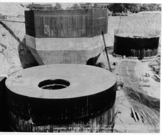
This
photo shows a launcher area under construction before
back-filling. The structure in the foreground is actually one of
the propellant terminals, but it illustrates the basic design used for
the equipment terminal. You can see the open access hatch in the
roof slab. The actual equipment terminal is visible at the top
right and does not yet have a roof slab in place in this
photo.
|
The
above photo shows the back-fill method used in construction of the
launcher areas. Once back-fill operations
were complete, the propellant and equipment terminals would be well
below the finished grade. You can see black asphalt sealant that
has been partially applied to the exterior surfaces.
Once
the concrete had been poured, equipment and materials were lowered in
through the roof access and work began inside.
Let's
take a look underground...
|
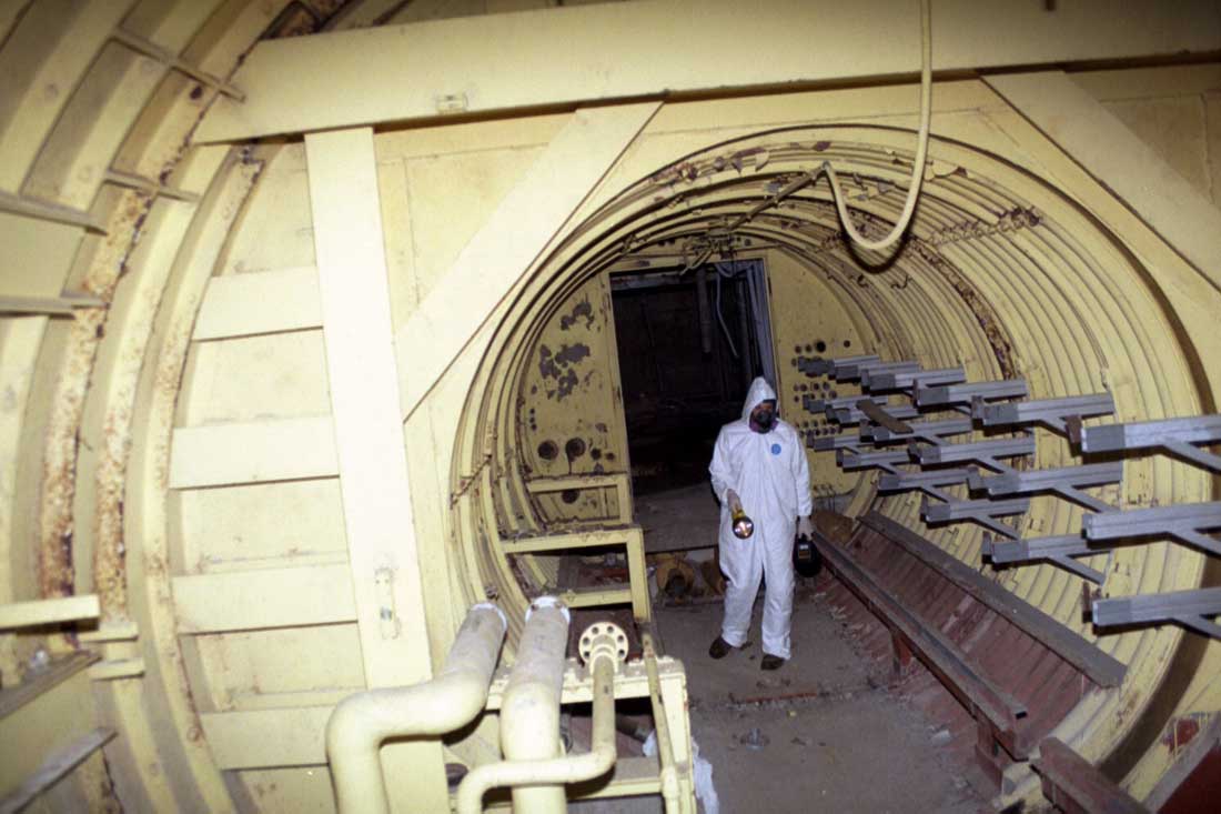
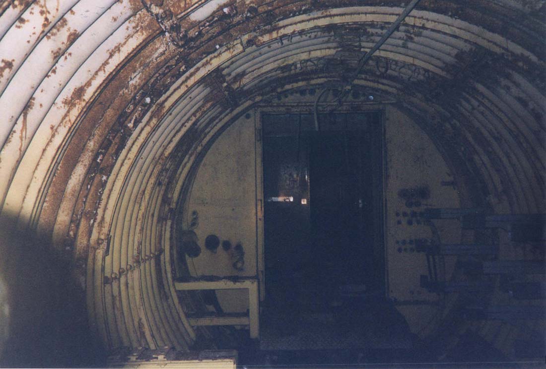
The
connecting tunnel to equipment terminal #1 at Lowry 724-C. Yours
truly, the silo gnome, guards the entrance with his 6V flashlight.
|
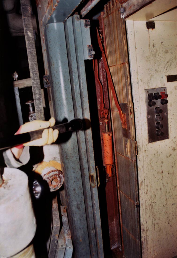
The
approach to the E.T.s shown here is pretty typical: door removed, flooring
removed, cable tray gone and piping and wiring gutted out. The doorway
(see below) sill plate is a hinged metal plate that simply rests over the
gap left by the rattle space.
|
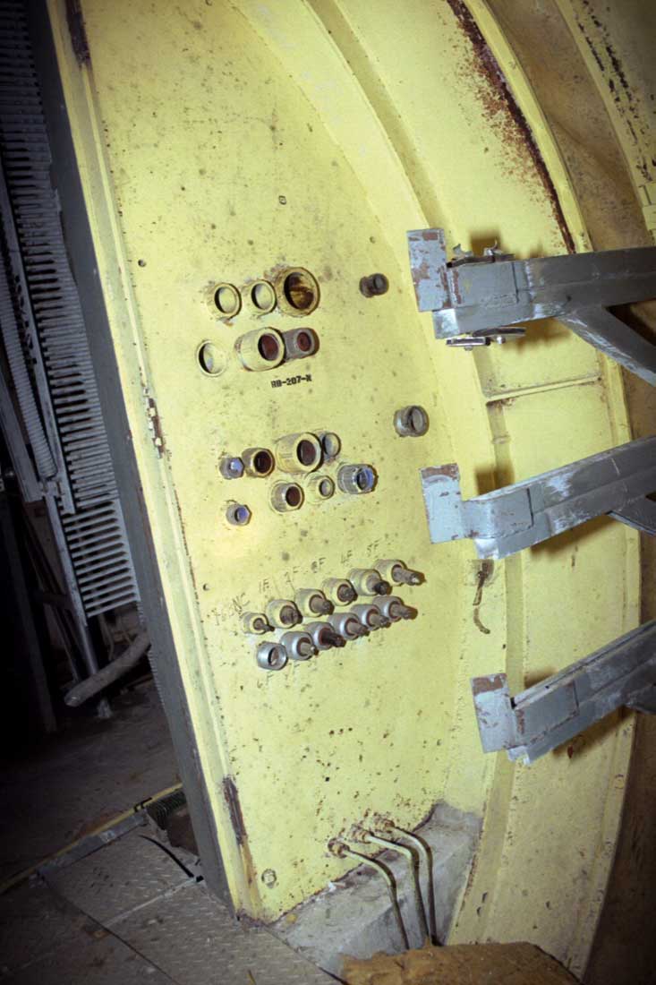
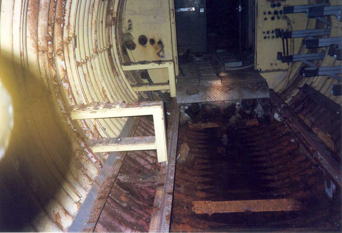
Cable
penetrations in the steel bulkhead at the entrance to E.T.#1 were
essentially air tight. This
was intended to attenuate any blast waves that might enter the complex
and prevent extensive damage to the other launchers that could take them
off alert status (meaning that they would not be capable of launch).
Notice how the door was installed to open outward.
|
|
This
is the considerably-more-damp approach to E.T.#2 at 724-C. There
is a lot more corrosion and even some standing water in the tunnel here.
|
|
Moving
closer to E.T.#2, you can see the rust and effects of the condensing
moisture here.
|
At
Lowry 724-C E.T.#3 This area is usually flooded by water back-flowing into
the tunnel from the missile silo which is flooded to a depth of about 100
feet.
|
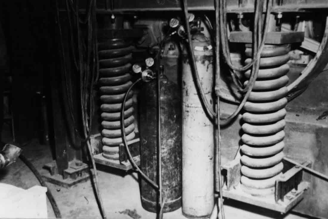
Level
I: Construction photo showing spring
shock mounts for the large utility air compressor. The
compressor's large flywheel is visible in the top right. Welding
equipment stands by in the foreground. This compressor operated
valves and dampers in the AC/heating equipment and other pneumatic
controls and systems.
|
|
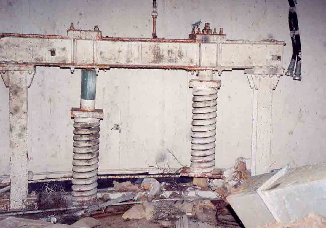
Recent
photo showing the absence of not only the utility air compressor but the
platform upon which it once rested. Let me tell you, those are
some serious springs right there. The black stripe in the
background is the neoprene seal covering the rattle space between the
wall and floor.
|
|
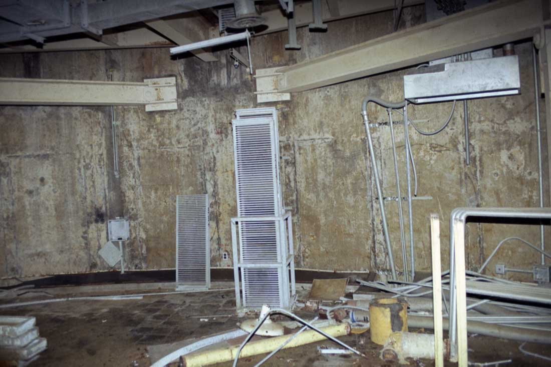
Construction
photo showing newly-installed cable tray running down through the floor
to the level below
|
|
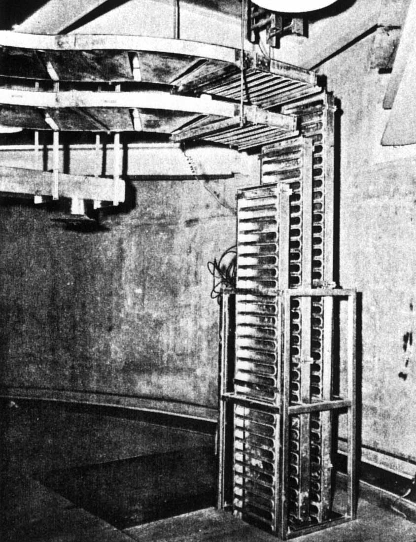
Photo
circa 2001 of 724-C E.T.#1 level III showing remnants of the inter-level
cable trays. Note the spring beams mounted to the wall on either
side. These are the beams from which the entire floor is
suspended. One of the vertical hanger assemblies can be seen near
the top right in this photo.
|
|
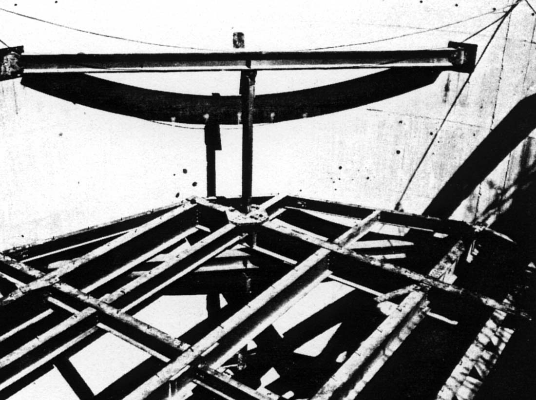
This
construction photo shows how the top 3 levels of the equipment terminals
were suspended from above. The steel sub floor shown here later had
a poured concrete slab added on top. The vertical hanger shown has
pivots on both ends to allow the floors to move hoizontally. Four
such hangers per floor supported the entire weight for levels
II-IV.
|
|
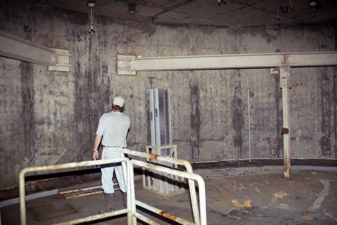
Circa
1999: Mr. X inspects the spring beam and hanger supports on level IV at
724-C E.T.#1. The vertical hanger can be seen on the right,
attached to the heavy beam by pivoting connectors.
|
Level
III, the Launch and Checkout level, used to be occupied largely by large
logic racks like the ones in the following 2 photos. Much of this
equipment was probably far too sensitive and valuable to be left behind, and
so far I have not seen any of the logic gear left behind at a site.
However, I have seen some test and checkout gear in private hands, so
apparently not all equipment was removed by the Air Force after closure.
|
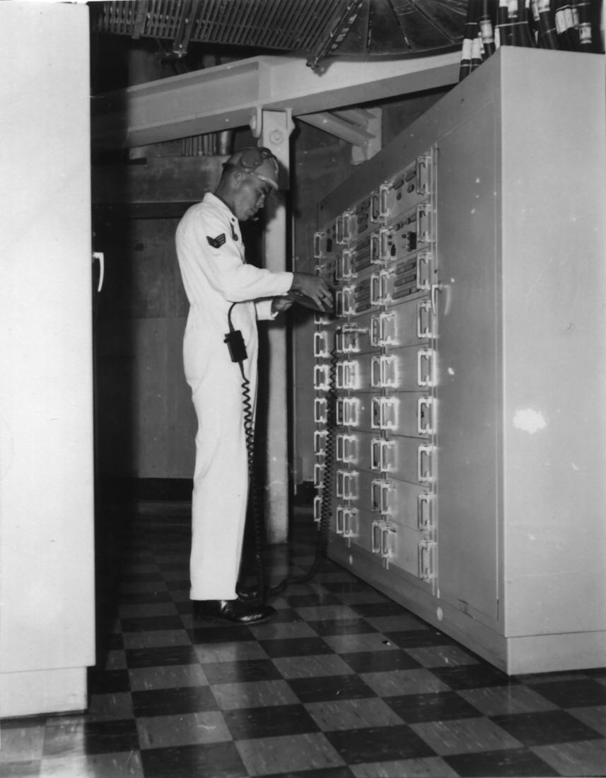
A1C
Brannon at the logic racks for Control Monitor Group 2020 on Level
III. These racks controlled elements of the Propellant Loading and
Pressurization System and the R/V subsystem monitoring and the fuzing
system.
Near
Airmen Brannon's head you can finally get a good look at how the hanger
pivots are put together.
|
Take
a look at the large cables emerging from the tops of these racks. Most
of the equipment here runs on DC power which requires much larger cabling
than AC for transmission even over short distances. Its no wonder that
none of that cable was left behind since it would have been quite valuable.
|
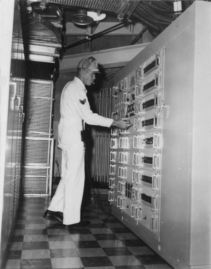
A1C
Brannon, this time at the racks for Control Monitor Group 2030 on level
III. Control Monitor Group 2030 is comprised of the Accessory
Supply Subsystem and the Radio Inertial Monitoring Equipment (RIME).
The
Accessory Supply Subsystem controls and monitors electrical, hydraulic
and AC services to the missile, launch and control checkout systems and
provides backup DC power. RIME
monitors the airborne guidance system and its state of readiness.
|
|
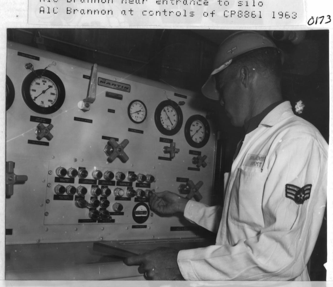
A1C
Brannon at the Missile Auxiliary Pumping Unit which served stages I and
II of the missile among other systems. This unit was located on
level II. Note the checklist in his left hand.
Photo
courtesy of Fred Epler
|
|
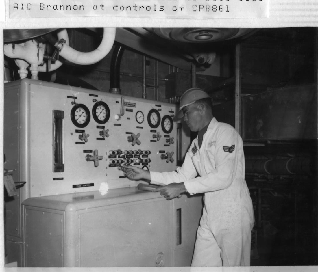
Another
look at the Missile Auxiliary Pumping Unit with A1C Brannon
Photo
courtesy of Fred Epler
|
|
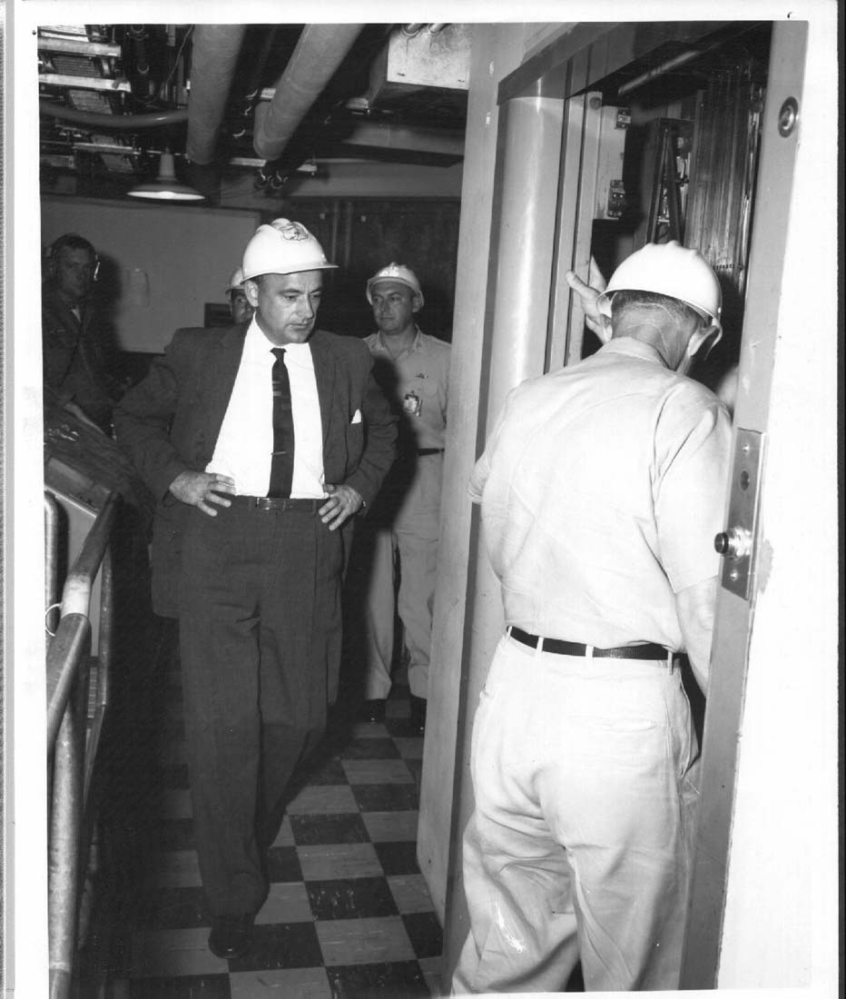
VIPs
being shown around the equipment terminal. (level III) I
believe that is Colonel Proctor heading into the
elevator. He is followed by Under Secretary of the Air Force DR.
Joseph V. Charyk. Date of photo is April 1961.
My
thanks to Fred Epler for identifying Under Secretary Charyk.
|
|
Level
II: The personnel elevator at 724-C E.T.#1 circa 2002
|
Up
to this point, I've been jumping around with the pictures of the equipment
terminal to make "then and now" comparisons, but from here on I
will be going by floor, starting with level I.
|
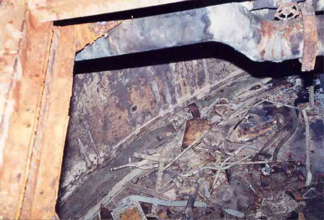
Level
II: looking down through the access hatch into level I. This is
E.T.#2 and you can see the effects of seasonal flooding on the walls and
junk on the floor. Everything on level I is badly corroded or has
a layer of dirt/mold/scum on it.
|
|
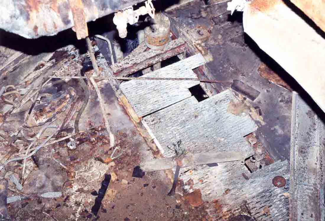
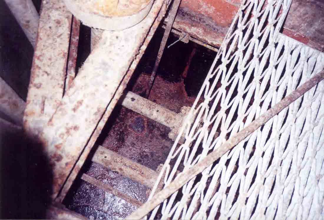
Another
view from above into level I. The sections of steel grating were
once used
to cover a pipe trench carrying large hydraulic lines from the pumps
which used to line the trench.
|
The
equipment terminals at 724-C today are largely torn up like most of the complex,
their valuable salvage was easily removed through the 10' equipment hatch in the
ceiling. #1 still has the hydraulic accumulator but not much else.
#2 has suffered a fair bit of flooding and is a mold garden. #3 is flooded
on levels I and II, making exploration difficult to say the least.
|
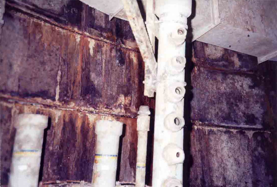
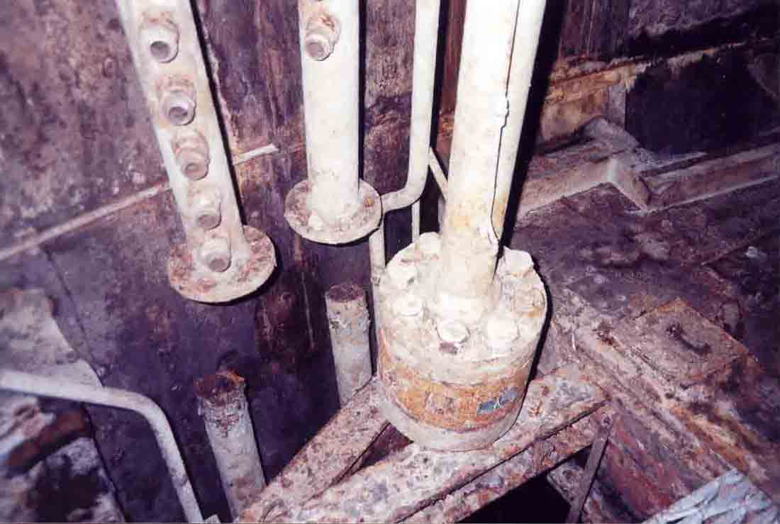
Level
I: Hydraulic lines and connectors. These lines ran up the wall to
level II where they traveled through the utilities tunnel to service
the missile and silo systems.
|
|
Hydraulic
lines on Level I that once ran from pumps nearby up to Level II and out
the utilities tunnel. This area appears
to flood on a seasonal basis and is horribly rusted out and covered with
mold and mildew.
|
|
Level
I: A view down into the sub-floor where a distasteful accumulation of
really foul-looking water has condensed down to a thick, dark-red
coagulation of filth. On the surface floats a scabrous crust of
unknown composition. I suspect that the color may be from
discarded hydraulic fluid or maybe just rust. Either way,
nasty-looking stuff!
|
|
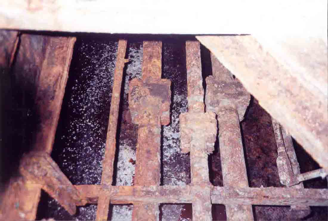
Level
I: Another view of the sub-floor space showing horrifically-rusted
hydraulic lines with scum-encrusted muck below. Note the white
speckles-- that is a large mold colony residing on the surface of the
crust.
|
|
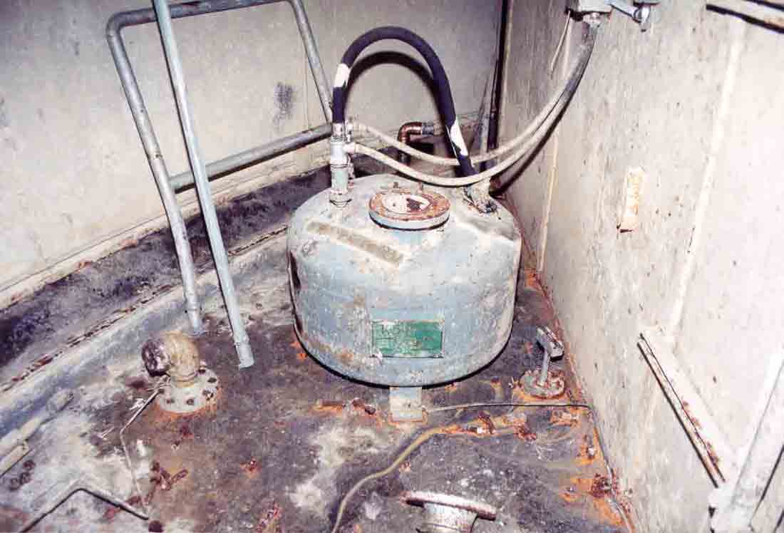
Level
I: A most indispensable piece of equipment in any manned underground
facility, this is the Sewage Ejector. This vessel stored air
pressure provided by one of the numerous compressors in the E.T.,
utilizing it to force sewage up and out from (I presume) another larger
storage tank to the surface and into the sewage stabilization
ponds. Hope it never failed. Not only could things get
rather unpleasant, but it was quite a walk to the next latrine in one of
the other E.T.s or back to the Control Center or Power House-- about a
good quarter mile or more.
|
|
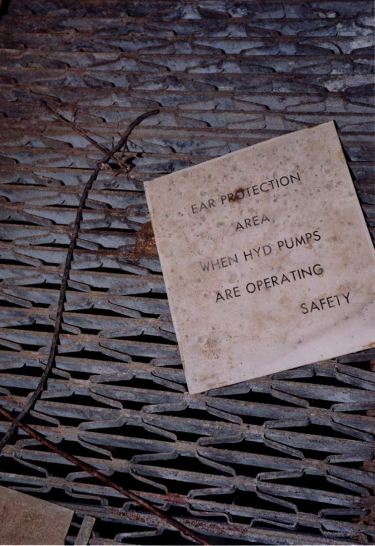
Level
I: A discarded sign rests on the steel-grille flooring. Its not
hard to imagine four large pumps running in concert being quite loud inside a concrete and
steel hat box.
|
|
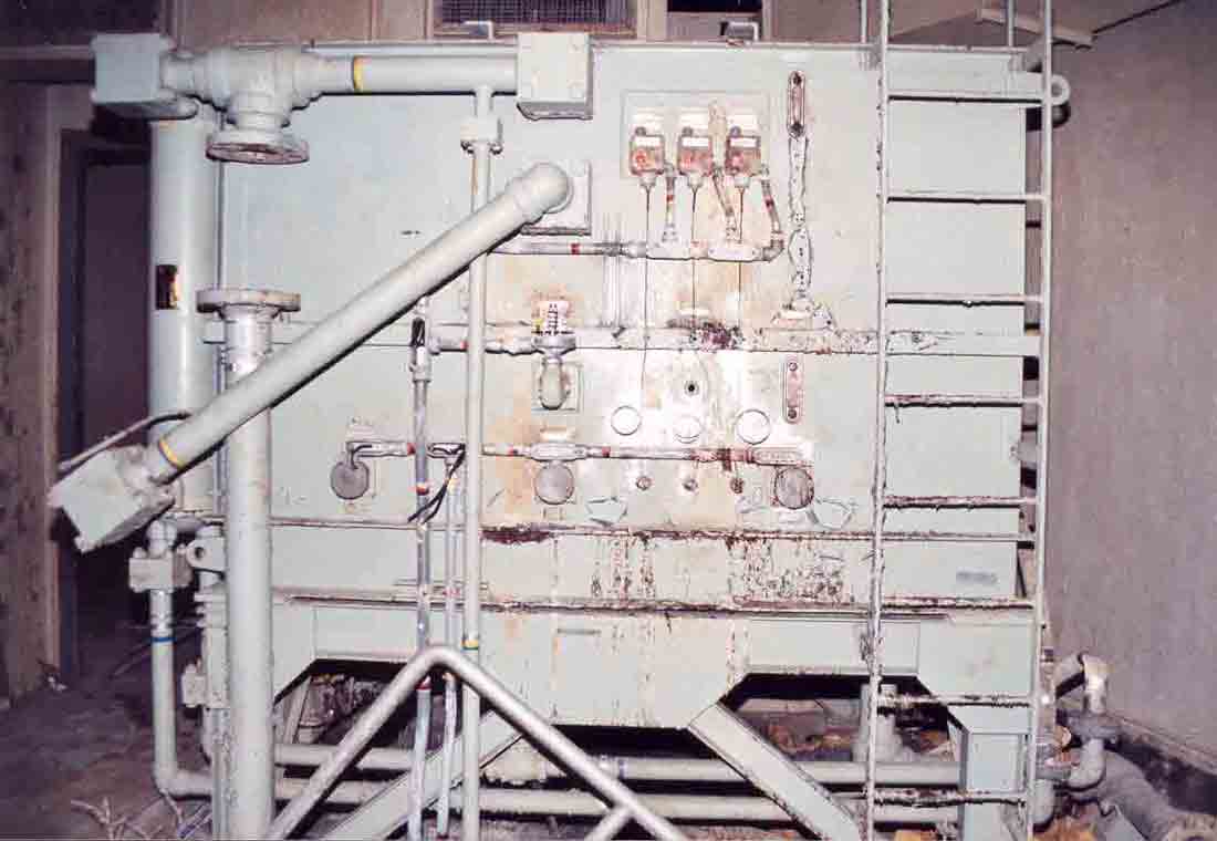
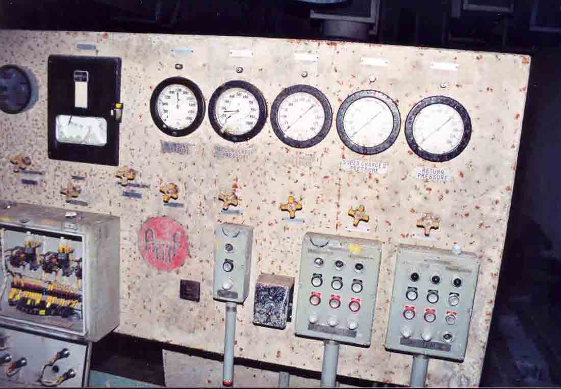
Level
I: This is the giant hydraulic accumulator-- essentially a large
reservoir for hydraulic fluid. It also heated and filtered the
fluid as well-- a lot of it. This unit stands over 8 feet tall and
is about 8' x 6'.
|
|
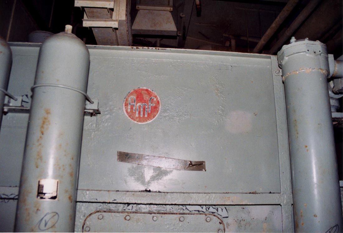
Level
I: The hydraulic accumulator viewed from the side. The bowlers out
there will likely recognize the manufacturer's logo from automatic
pin-setters found in alleys all over the US and even abroad. AMF,
or American Machine and Foundry, has a long history of defense contracts
going back to the beginning of the Cold War. They used to be
involved in the manufacture of everything from bicycles to nuclear power
plants. Known today as Qubica-AMF, the company is now focused only
on bowling and recreation.
|
For more blather about AMF
and its role in the Titan I system, see section I on the Missile
Silos.